Enrique
-
Proof of concept renders
07/14/2018 at 16:24 • 0 commentsOne of the main aspects of wearables is the aesthetics. I wanted to know how well the power harvesting module would fit in one of the rings which I have in mind, so I 3d designed all the components respecting the measures. Here are the renders:
![]()
The power harvesting module is in the yellow flex board, with the two solar cells on the left and four supercapacitors on the right. The rest of components are 3 RGB leds and a microcontroller with some more circuits that I will explain in to my smart ring project page.
![]()
Here is with a plastic shell, three diffusers for the LEDs and two holes for the solar cells.
-
Making the first schematic
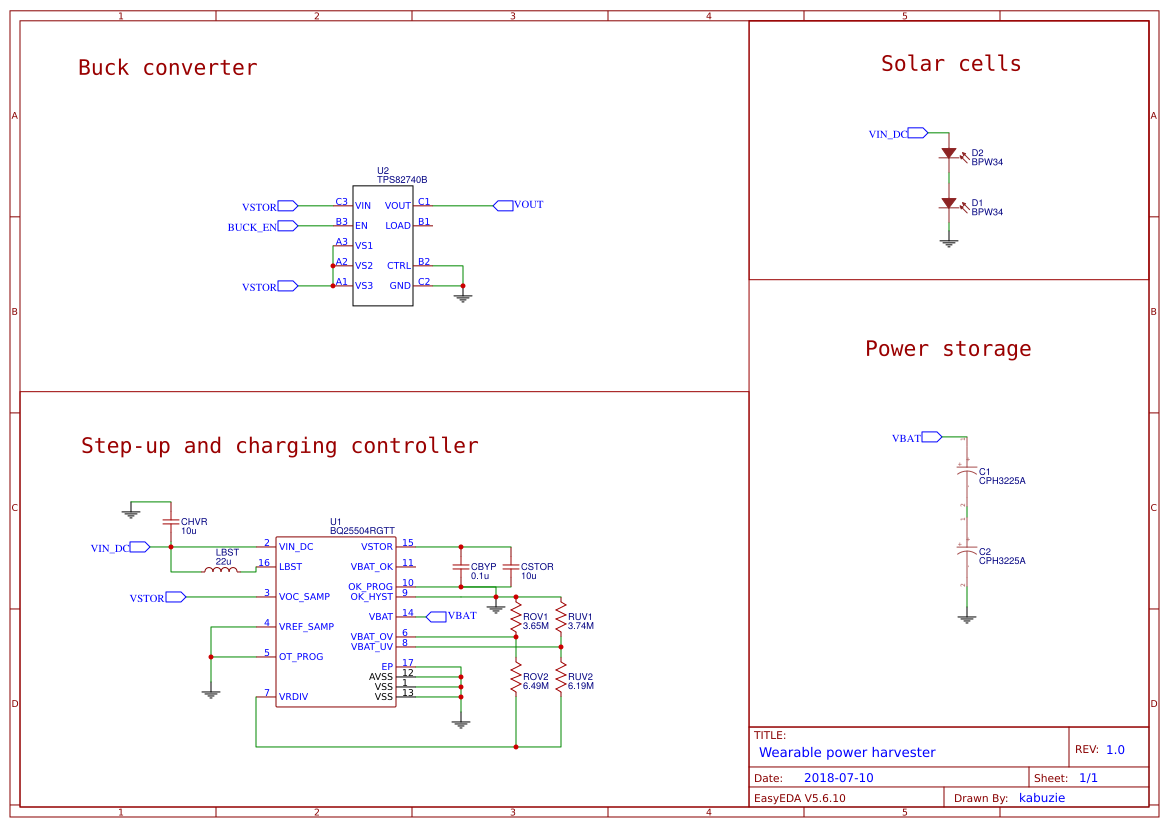
07/10/2018 at 20:50 • 0 commentsI have sketched a quick schematic about the general idea, but needs be polished and tested so shouldn't be taken as the final one.
![]()
There are some details:
-The CBYP should be a low leakage
-The CBYP should be placed close to VSTOR and GND
-The CSTOR should have a low ESR, and it's value is related to the cold start efficiency and time
-Is possible to add more solar cells on parallel or in series, but I prefer on parallel for not exceed the max input voltage.
-The inductor should have similar specs to one of the given in the datasheet
-
Choosing the right resistors
07/09/2018 at 22:39 • 0 commentsThe BQ25504 have the ability to provide undervoltage and overvoltage charging regulation, which ensures that the storage component doesn't get damaged. For programming this threshold certain resistor values are required. There's a formula on the datasheet, but Texas Instruments have a spreadsheet which calculates it.
The sum of the resistor divider should be equal to 10Mohms and the undervoltage calculation is the next following;
VBAT_UV = 1.25V(VBIAS) * (1 + RUV2/RUV1)
so, with RUV1 = 3.74MOhm and RUV2 = 6.19MOh, we get: 3.32V
The overvoltage calculation is the next following;
VBAT_OV = 3/2 * 1.25V(VBIAS) * (1 + ROV2/ROV1)
so, with ROV1 = 3.65MOhm and ROV2 = 6.49MOh, we get: 5.21V
We have to take into account too the hysteresis values, which are:
VBAT_UV_HYST = 80mV
VBAT_OV_HYST = 35mV
The IC also provides two more resistor dividers, the VBAT_OK, which turn on a flag when the battery voltage is on certain threshold and the MPPT. I'm going to try to avoid using both, for having more space and making the pcb traces simpler. The battery voltage can be monitored with an external uC, so the VBAT_OK flag is not required. The MPPT provides a more optimal energy harvesting, but for testing purposes I'm going to disable it, and if I see that makes a different, try to implement it.
-
Designing a few breakout boards
07/03/2018 at 22:21 • 0 commentsBefore messing up soldering into a custom pcb, I want to test the BQ25504 with discrete components, and in a more debuggable way (is a relatively expensive IC for a student), for that reason I have sketched a couple of breakout boards and ordered it to OSHPARK
I have also made another for the TPS82740B, which is packed in a solder ball package
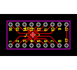
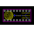
BQ25504:
Front PCB:
![]()
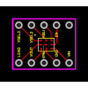
Back PCB:
![]()
I added the thermal pad as an extra pin, for testing purposes.
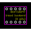
TPS82740B:
Front PCB:
![]()
Back PCB:
![]()
Both breakout boards are in the download section
Flexible wearable power harvester
A miniature power harvester solar-based for wearables, IoT and my smart ring series