Luke
Luke-
First timer assembled! Electronics, firmware and mechanical design update
12/02/2018 at 17:30 • 0 commentsSome time has gone by since my last log update.
ELECTRONICS
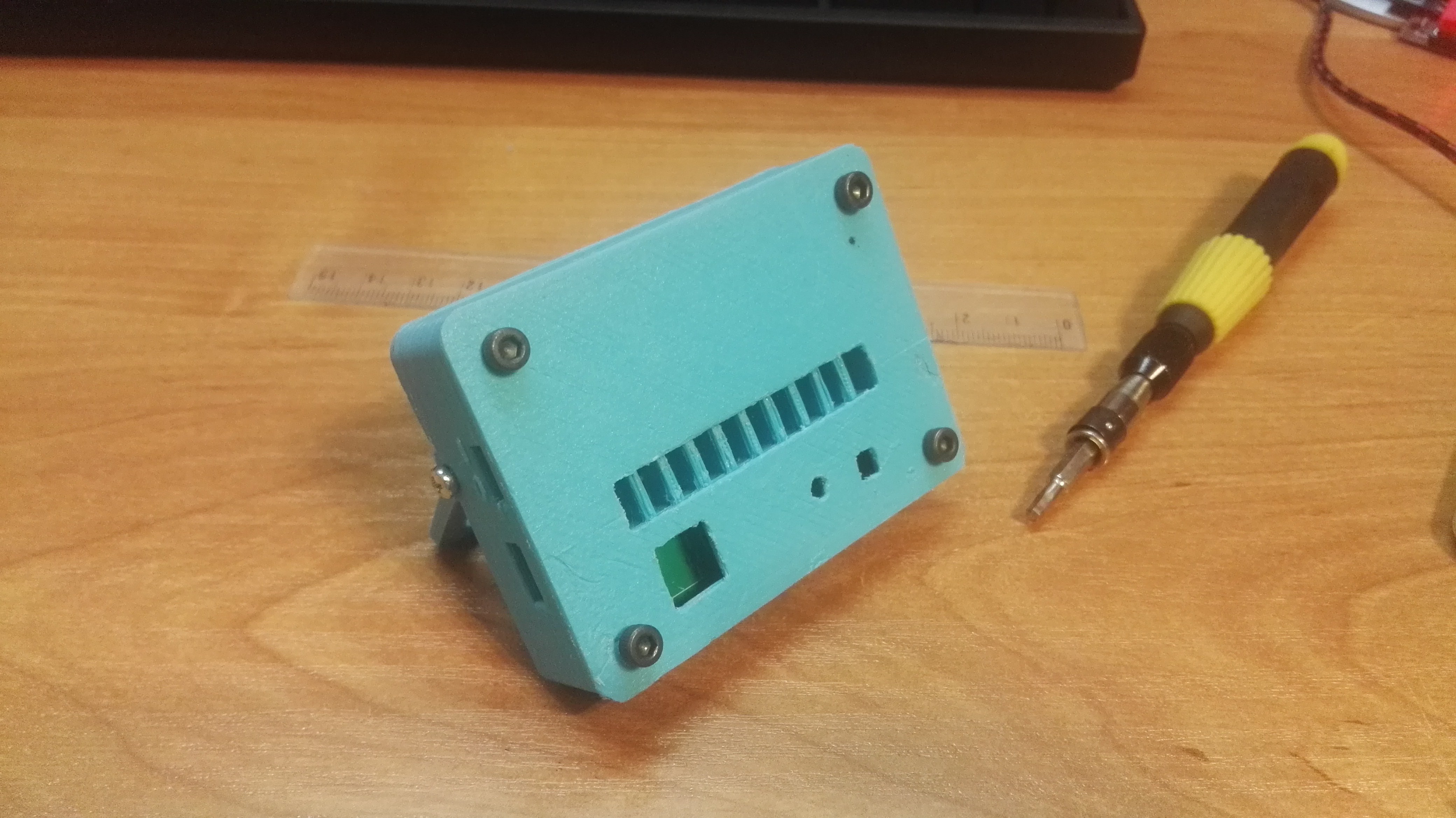
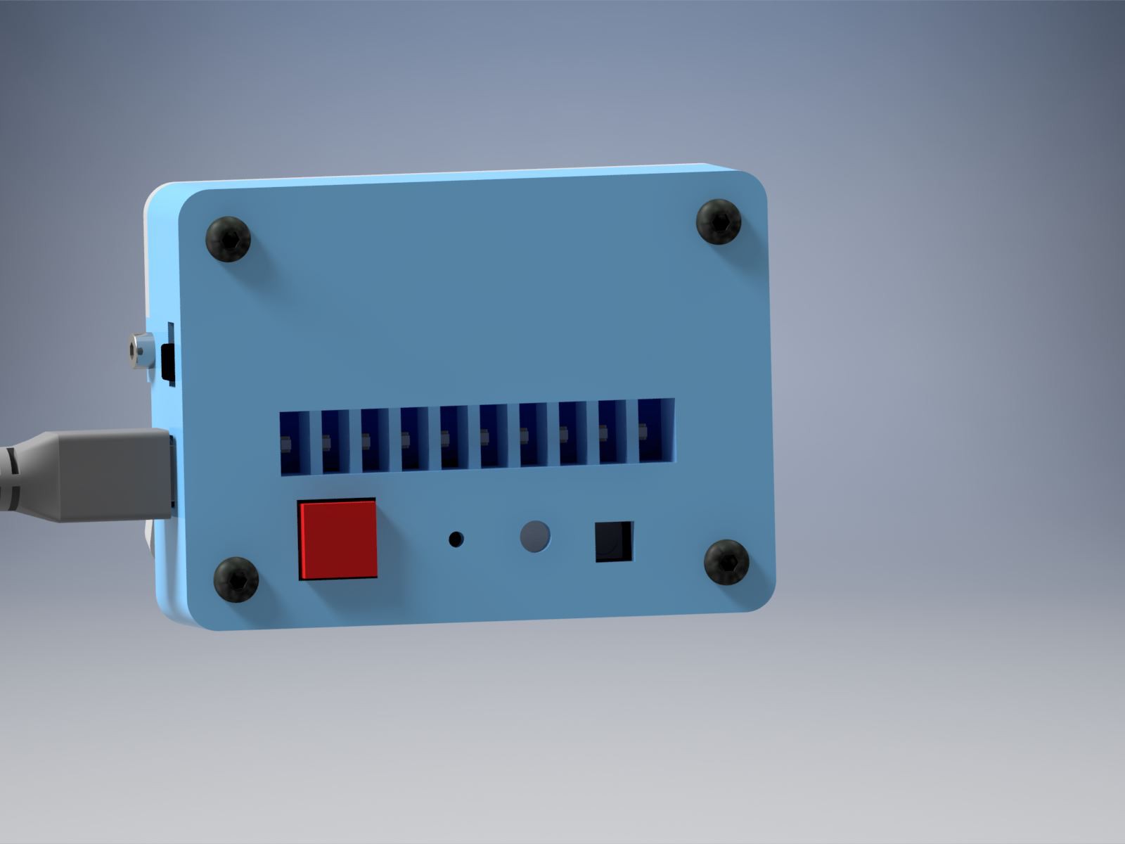
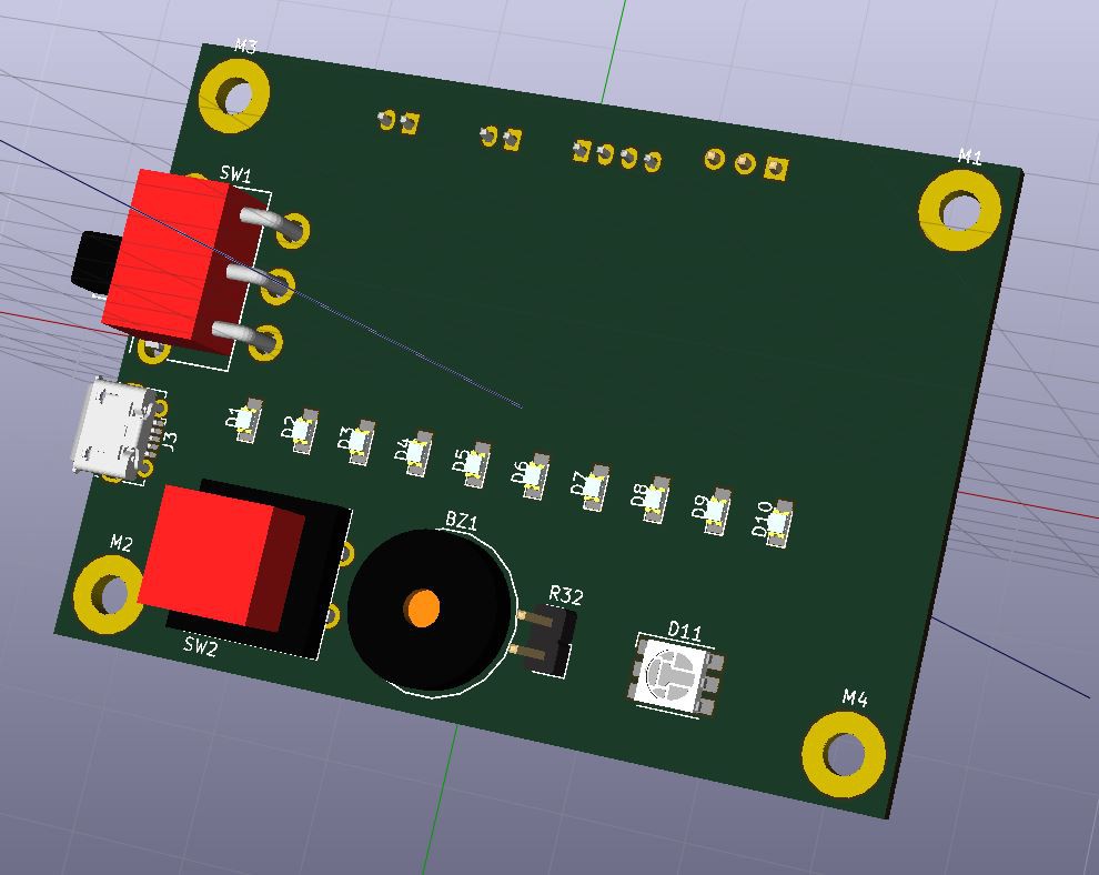
During that period the PCBs and parts arrived and I assembled one timer :)
The assembly process went smooth. The smallest parts are LED driver and battery charger (0.5mm pitch QFNs) and I used microscope when soldering them down. Rest of the components went easy (passives are in 0805). On hiccup I encountered was swaped (misplaced) labels of two resistors (R21 and R22), but I spotted it pretty quickly, since voltage converter was not working properly with these resistors swapped (they provide feedback voltage to the converter).

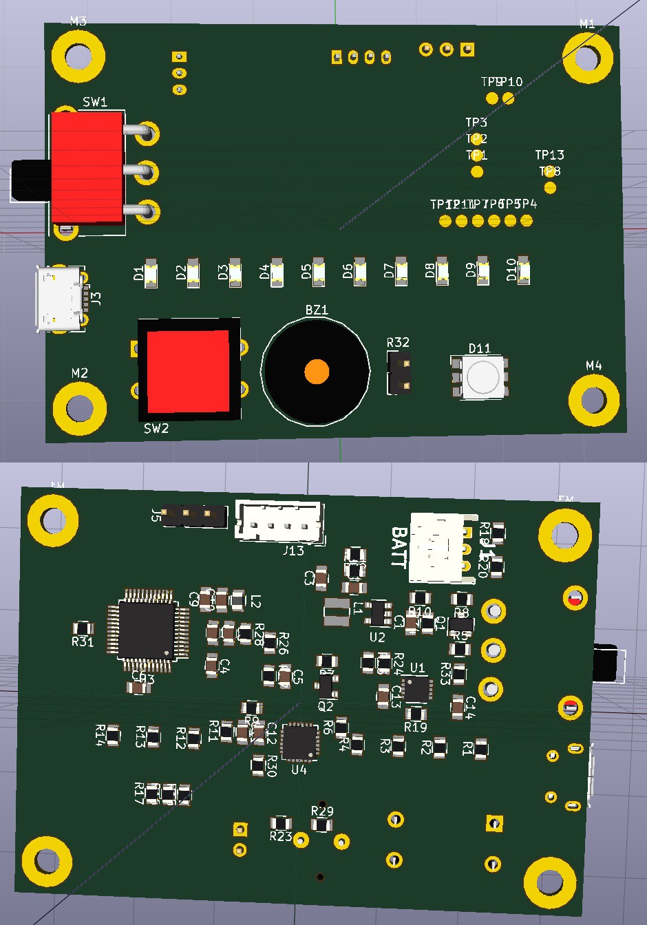
Back of the PCB 
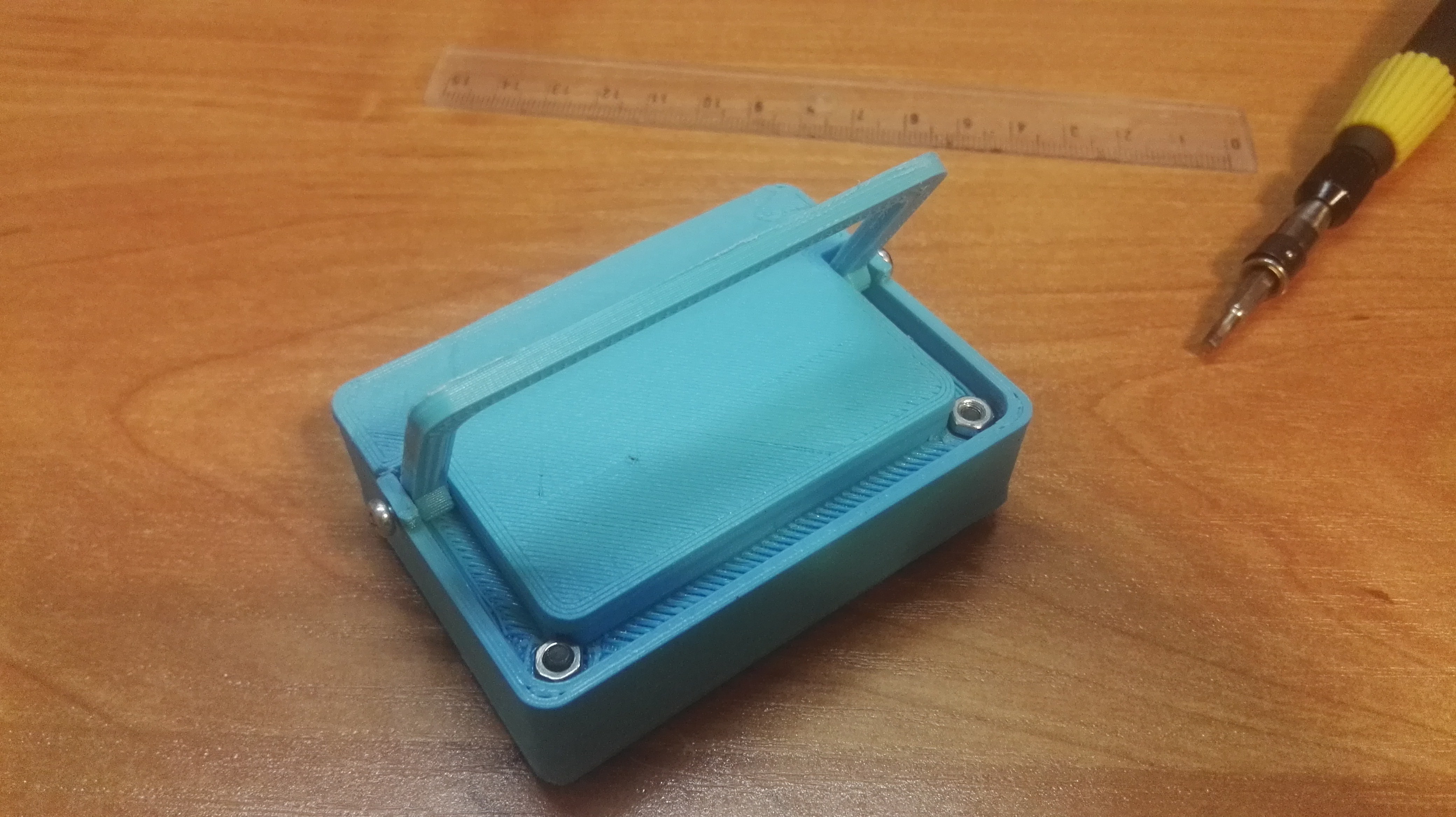
Front of PCB with LEDs turned on FIRMWARE
After timer was assembled, I moved on to initial firmware development. I tested two toolchains/compilers: SDCC and ST Visual Develop (with Cosmic toolchain).
As far as I can see, there's no straightforward way to use debugger with SDCC toolchain (I may be mistaken). STVD+Cosmic has debugging capability built-in the IDE, which was a big plus for me. Also libraries provided by ST (called SPL - Standard Peripheral Library) were better suited for Cosmic compiler.
I created 'blinky' projects for both SDCC and STVD and after that decided, that I'll use STVD+Cosmic combo.
So far I've implemented 'millis' timer (using Timer2) and LED driver (using SPI and DMA).
Code is available on GitHub.
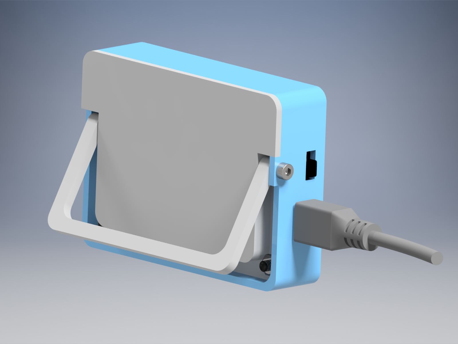
MECHANICAL
Case elements were 3D printed to see how they fit. The result is not bad, but I had to make a few changes in the design. Next week I'll probably print improved design.
![]()
![]()
-
PCB layout finished
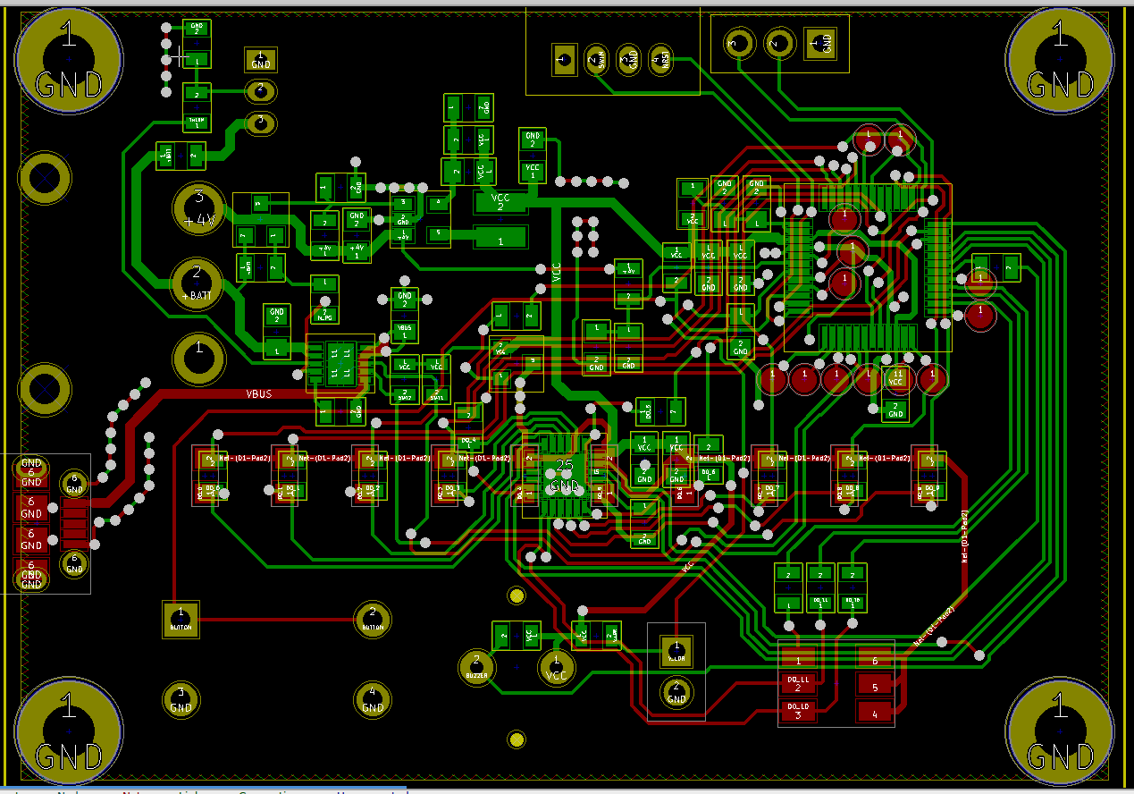
08/20/2018 at 20:18 • 0 commentsSo today I finished layout of the PCB :) Together with components placement it took around 7 hours to finish. I had a small problem with ground plane - during routing I was not connecting GND pads of the components, so after creating GND plane pours on both layers I had to move some tracks around to create proper planes (also I added a few GND vias here and there).
PCB with filled areas display off:
![]()
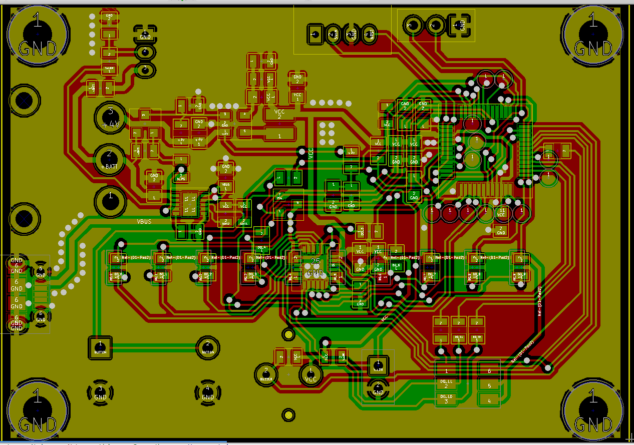
PCB with filled areas display on:
![]()
Next step is generating production files (gerber files) and sending it to manufacturing :)
-
Case design & components placement
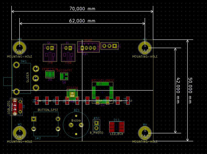
08/15/2018 at 12:25 • 0 commentsAs mentioned in previous log entry, I had to export 3D PCB model (with all major components), so that initial case design can be created. To do that, I used kicad StepUp plugin for FreeCAD. Exported STEP file was then loaded into Autodesk Inventor and I could start designing the case elements.
After a few hours of work, I had initial case design:
![]()
![]()
During the process I made small changes to components placement on PCB (like moving a switch a bit, etc.).
Now I could move on to PCB layout. I started with placement of all smaller components (like passives). The result is shown below (I'll take care of silkscreen later):
![]()
Next step is routing all the tracks :)
-
Initial components placement
08/01/2018 at 21:13 • 0 commentsSo I spent a few hours on creating footprints and 3D models for buzzer, slide switch, push button and other minor components. I wanted to have STEP models associated with WRL files, so that full 3D model can be exported. The 3D model will then be imported into Inventor, so that I can design a nice enclosure for the whole project.
When footprints were ready, I carried out initial components placement:
![]()
3D models are also visible in KiCad:
![]()
Next step is generating 3D model of the whole board (I use kicad StepUp plugin for FreeCAD - https://sourceforge.net/projects/kicadstepup/), which will be imported into Inventor. After that, I'll design initial enclosure and check if components placement is ok. When all main components placement is settled, I'll move on to PCB layout :)
-
MCP73833 NTC resistors calculations
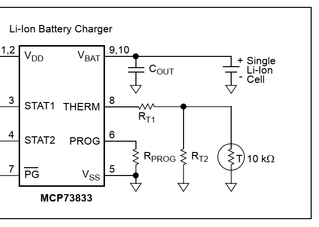
07/01/2018 at 10:13 • 1 commentThe MCP73833 cell charger has THERM input, which enables the chip to monitor the temperature of a battery:
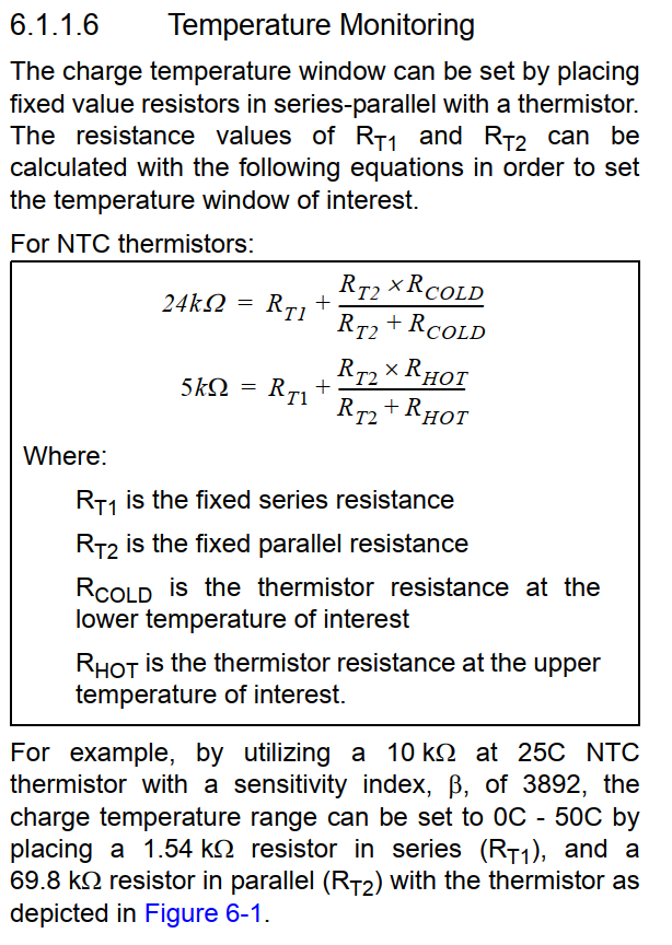
By choosing appropriate R_T1 and R_T2 values (depending on NTC thermistor parameters), the designer can adjust allowed operating temperatures (e.g. from 0C to 50C), which is described in the datasheet:
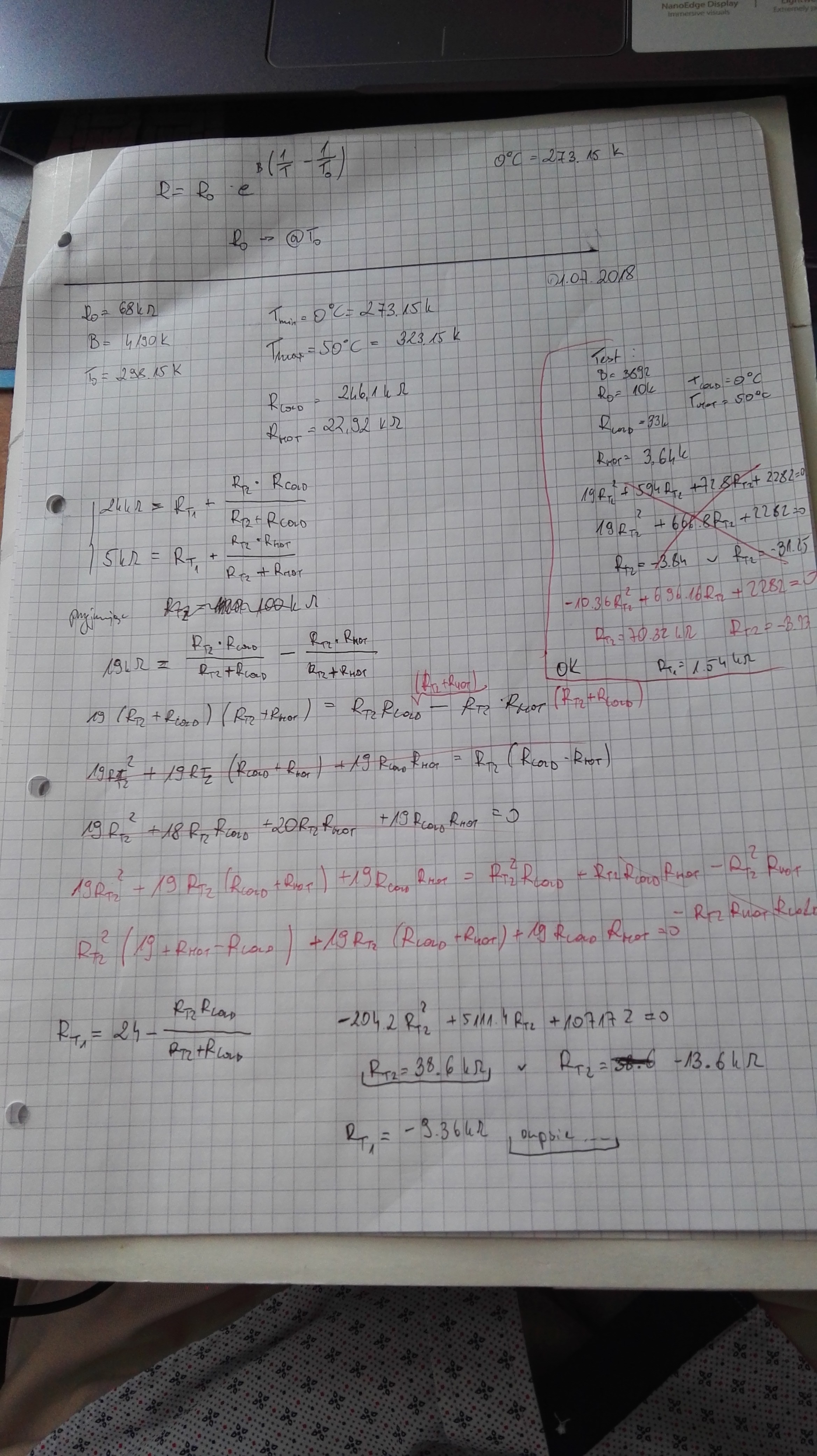
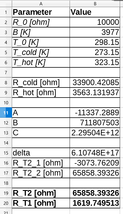
So far, so good. But solving above equations for R_T1 and R_T2 requires calculating NTC resistance two times, then calculating quadratic equation parameters (A,B,C), then calculating R_T2 and finally calculating R_T1. It gets really annoying after second iteration (since you chose wrong thermistor R_0 and R_T1 is negative...):
![]()
So I quickly created a spreadsheet document that calculates all that stuff automatically - just put in the thermistor parameters (R_0 and B) and T_cold and T_hot.
Now choosing the right NTC and resistors should be easy :)
-
LED driver added, working on BOM
06/30/2018 at 09:58 • 0 commentsLast time I mentioned, that I may add AS1122 LED driver to test it. In final version I would decide which metod I'd use to drive the LEDs: dedicated IC or PWM generated by the microcontroller.
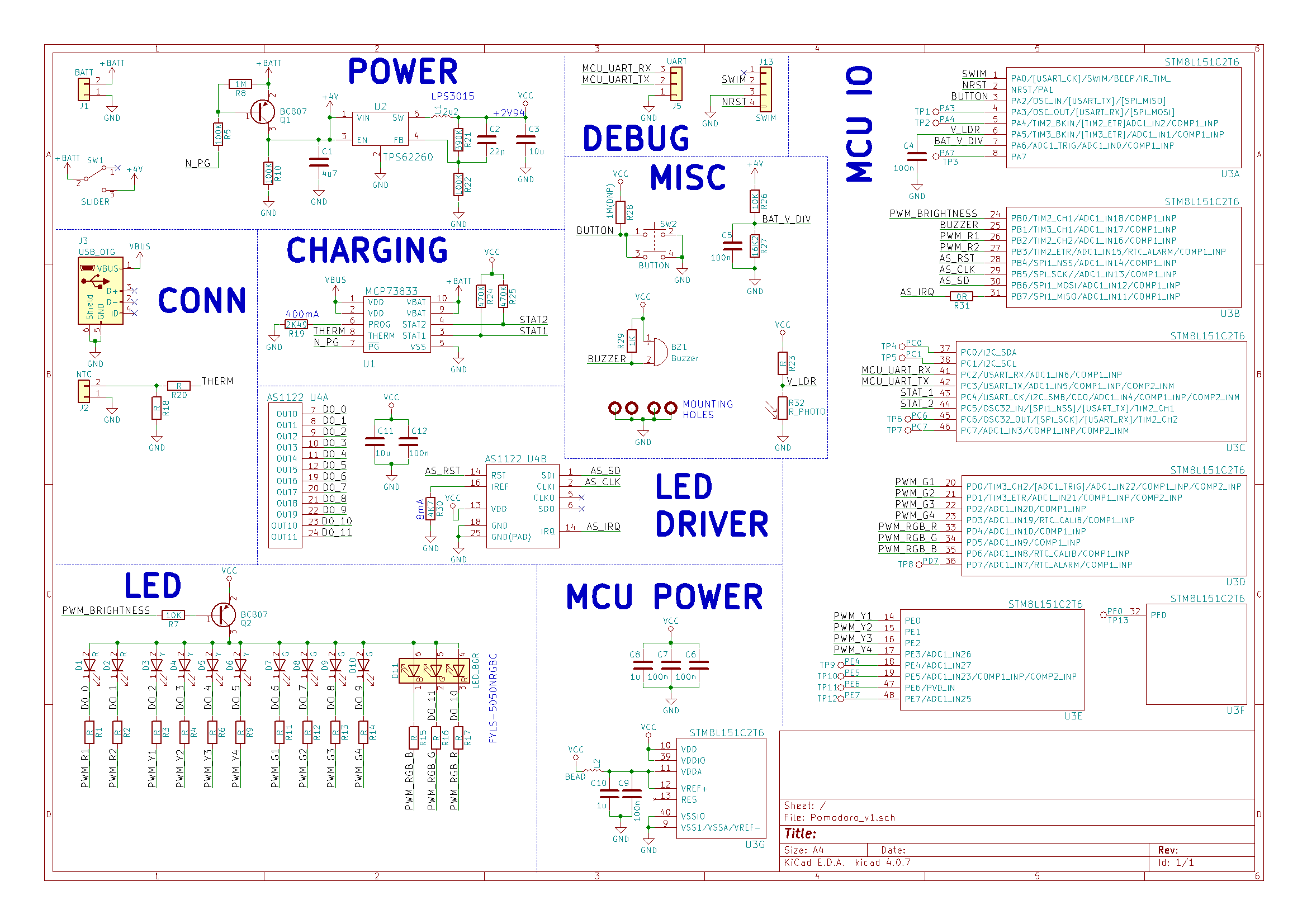
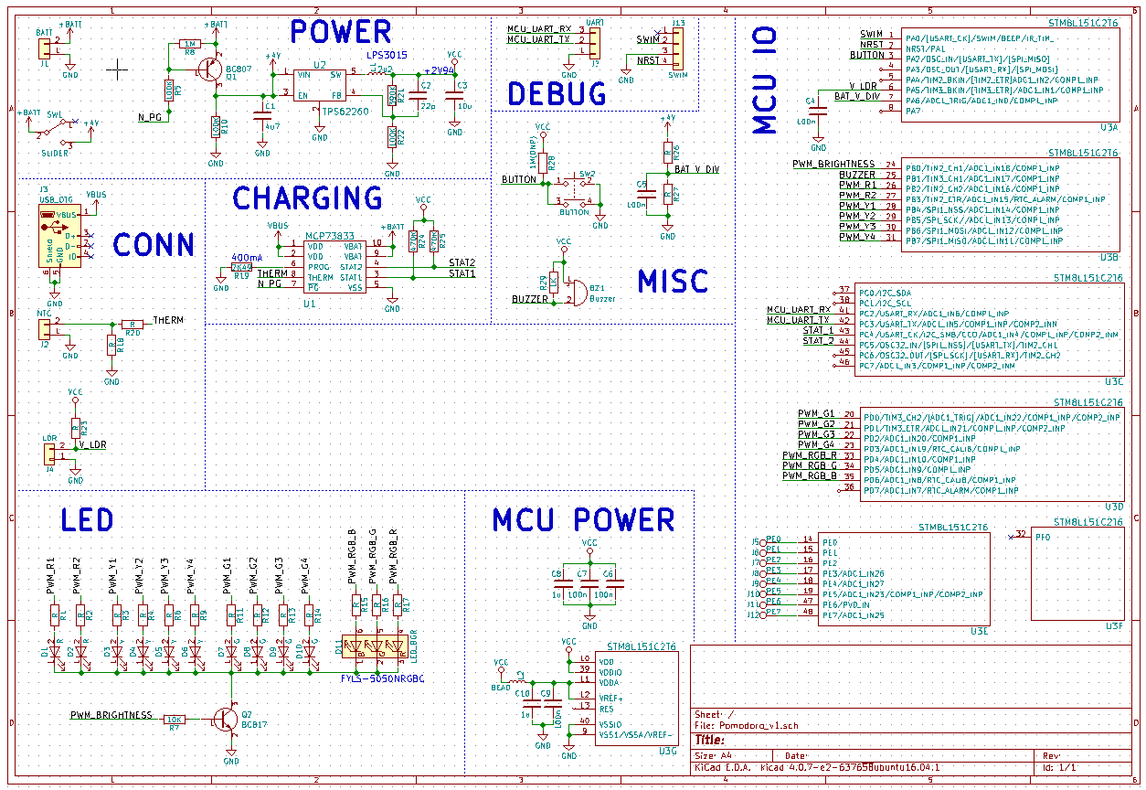
Right now the schematic looks like this:
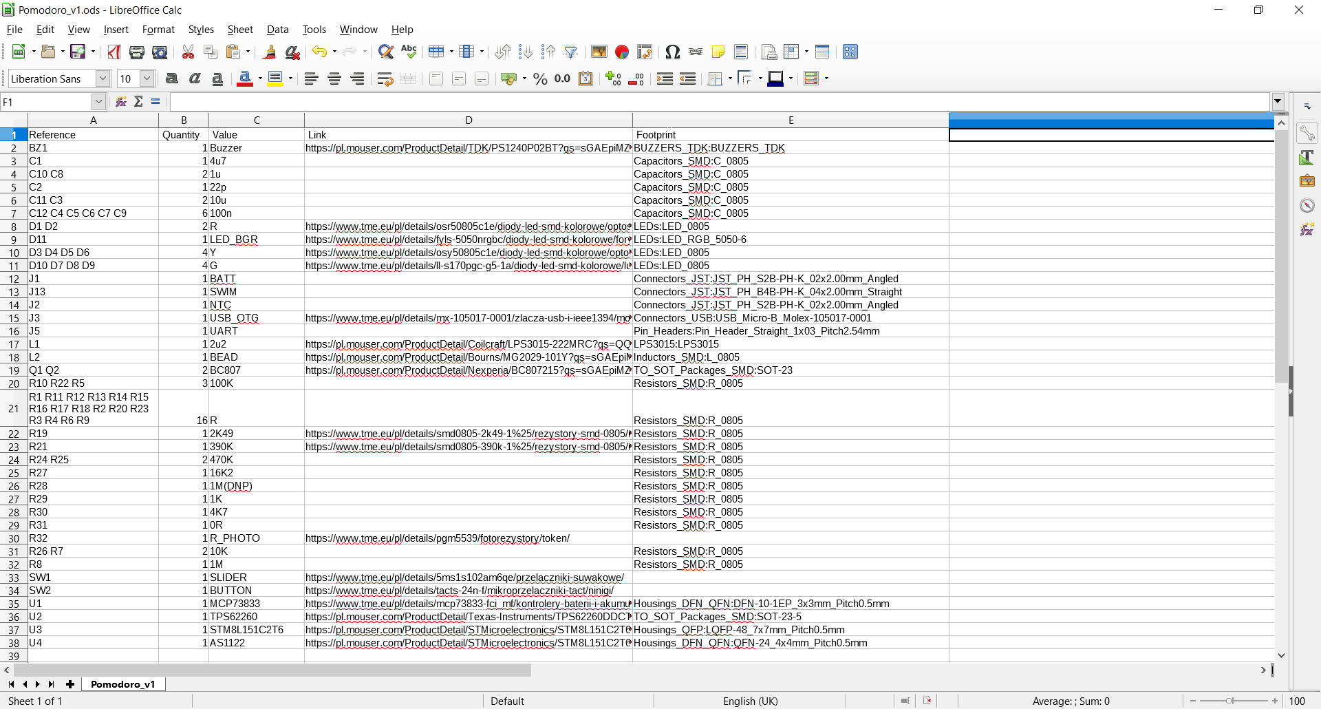
I started working on BOM by adding 'Link' fields to schematic components, so that generated BOM is automatically populated with links to distributor websites (I use Mouser and TME).
Exported BOM (to CSV format) opened in Calc:
All the BOM stuff is work in progress (not all fields are populated)!
-
Preliminary schematic
06/24/2018 at 12:46 • 0 commentsCurrently I've finished working on initial schematic:
![]()
Now I will create AS1122 (LED driver) symbol and add it to the schematic. After that footprints will have to be assigned.
-
Components selection
06/23/2018 at 15:22 • 0 commentsMy first step was creating requirements document (you can see it in DETAILS section). After that was done, I moved to components selection stage. I treated this task as a engineering exercise and decided to keep the parts cost as low as possible (while maintaining required functionality).
Microcontroller
Some time ago I stumbled upon STM8 family, which can be viewed as AVR competitor. So far I've only used AVR and STM32 microcontrollers and I wanted to try something new. I did some research in terms of peripherals (I needed around 20 I/O pins, at least two ADC channels and two timers) and memory.
Eventually I decided to go with STM8L151C2T6, which can be bought for $1.20 @100qty from Mouser. This MCU has 4kB of flash, 1kB of RAM and can run at 16MHz.
Battery charger
I want to charge the battery via USB port. The battery will probably have a capacity of around 500mAh. I looked for a linear charger that would automatically handle the charging process (CC-CV cycle, overtemperature protection etc.) with max current of around 500mA.
I found that MCP73833 fits my needs and it costs around $0.70 @100qty, which is nice.
Voltage regulator
Maximum battery voltage exceeds allowed MCU input voltage (3.6V), so I had to use some form of voltage regulation. I decided to go with buck converter to step down battery voltage to around +3.0V. My main requirement is good efficiency at low currents (a few milliamperes) and TPS62260DDC has great efficiency curve. Also, it's not that expensive: $1.08 @100qty.
LEDs driving
I did a bit of research on LED drivers. The LED bar will consist of 10 LEDs. I've found one promising chip: AS1122, but the price is pretty high ($1.73 @100qty).
One important note here: only one LED from LED bar has to be dimmed at certain moment (other LEDs are either on or off). Global brightness control (to accommodate to ambient light) of all LEDs can be done using one transistor. Individual LED control can be achieved by using software PWM and only PWMing the output of currently dimmed LED from LED bar.
Currently I decided to control the LEDs simply using MCU pins and one NPN transistor to control the brightness (see schematic in next log), but now I think that I may add AS1122 to the schematic, just to test the chip and compare the results.
Productivity Timer (a.k.a. Pomodoro Timer)
For people who want to focus on certain task, the Productivity Timer is a simple device that divides your time into well-defined blocks.