-
1Note: these instructions are for a previous version of OpenTorque. Go the the GitHub repo (https://github.com/G-Levine/OpenTorque-Actuator) for the latest instructions.
-
2Print the parts
- Use 50% infill and a wall thickness of at least 1.2 mm.
- Nylon is the recommended material for the sun and planet gears. I used Taulman Alloy 910.
- Print the planet gears on rafts to ensure the first layer comes out perfectly flat. Otherwise you can run into issues with the gears meshing.
- All the parts are designed to print without supports.
-
3Install the threaded inserts
Printed parts:
- Ring Gear
- Planet Carrier Front
Non-printed parts:
- 21x M3 threaded inserts
Instructions:
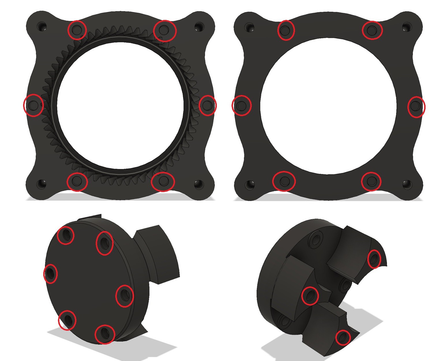
- Place the inserts in the holes (marked in red) and set them in place with a soldering iron.
![]()
-
4Assemble the planet carrier
Printed parts:
- Planet Carrier Front
- Planet Carrier Back
- 3x Planet Gears
Non-printed parts:
- 3x M3 14mm countersunk screws
- 3x 5x40mm steel dowel pins
- 6x F625ZZ bearings
Instructions:
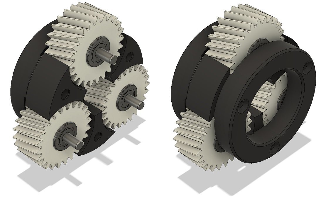
- Insert the F625ZZ bearings into the Planet Gears. Use two bearings per gear, one bearing goes on each side of the gear.
- Insert the 3 dowel pins into the 5mm holes on the Planet Carrier Front.
- Slide the planet gears onto the dowel pins. (depicted on the left)
- Place the Planet Carrier Back on (depicted on the right), and secure it in place with three M3 14mm countersunk screws.
![]()
-
5Assemble the gearbox
Printed parts:
- Ring Gear
- Front Plate
Non-printed parts:
- 2x 6813-2RS bearings
- 6x M3 14mm countersunk screws
- Planet Carrier assembly (from Step 3)
Instructions:
- Insert the 6813-2RS bearings into the Front Plate and the Ring Gear.
- Insert the Planet Carrier assembly into the Ring Gear. The side with the hole in it should go in first. (Depicted on the left and center)
- Place the Front Plate on (depicted on the right) and secure it in place with six M3 14mm countersunk screws.
![]()
-
6Install the encoder magnet
Printed parts:
- Encoder Magnet Holder
Non-printed parts:
- Turnigy Multistar 9235-100KV brushless motor
- 6mm x 2.5mm encoder magnet (comes with the encoder)
Instructions:
- Insert the magnet into the circular hole in the Encoder Magnet Holder (marked in red).
- Press the Encoder Magnet Holder onto the hexagonal head on the back of the motor.
![]()
-
7Assemble the motor mount
Printed parts:
- Motor Mount Housing
- Motor Mount Backplate
Non-printed parts:
- Motor with attached magnet (from Step 5)
- ENC2b encoder
- 87mm frameless cooling fan
- 7x M3 8mm low-profile cap screws
- 4x M4 14mm countersunk screws
- 6x M3 50mm countersunk screws
Instructions:
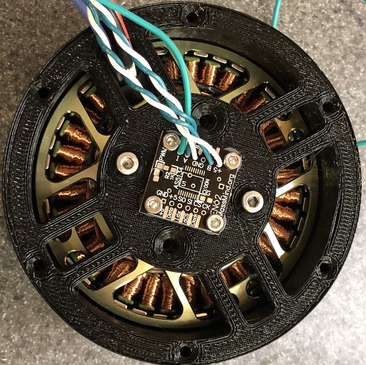
- Solder wires to the encoder PCB such that they exit from the bottom (see first picture below).
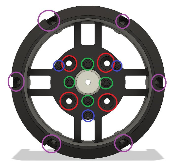
- Attach the motor to the Motor Mount Backplate (holes marked in red). Use the countersunk M4 screws. Make sure to orient the motor so the wires go through the semicircular wire-routing hole on the side of the Backplate.
- Attach the encoder (holes marked in green). Use 4 of the M3 cap screws. The screws thread directly into the plastic. The encoder IC should face inwards towards the motor (see first picture below).
- Attach the cooling fan (holes marked in blue). Use the other 3 M3 cap screws. These also thread directly into the plastic.
- Place the Backplate on the Motor Mount Housing and line up the 6 outer screw holes (marked in purple). Ensure the side of the Housing with the 6 cooling cutouts faces away from the Backplate, not towards it.
- Put countersunk M3 50mm screws through the 6 outer screw holes (marked in purple).
![]()
![]()
-
8Final assembly
Printed parts:
- Sun Gear
Non-printed parts:
- Gearbox assembly (from Step 4)
- Motor Mount assembly (from Step 6)
- 4x M3 14mm countersunk screws
Instructions:
- Attach the Sun Gear to the front of the motor with four M3 14mm countersunk screws.
- Place the Motor Mount on the back of the Gearbox assembly. Line up the 50mm M3 screws (installed in Step 6) with the 6 threaded inserts on the back of the Gearbox.
- Tighten down the 50mm M3 screws.


Discussions
Become a Hackaday.io Member
Create an account to leave a comment. Already have an account? Log In.
Hi! How did you insert the bearings into the planet gears? It looks like the ID of the chamfered entrance is 14 mm but the OD of the bearing is 16 mm. Did you use a drill to widen the hole after printing?
Are you sure? yes | no