Close
0%
0%

OpenTorque Actuator

A powerful, compliant actuator for legged robotics

Similar projects worth following
OpenTorque is an open-source implementation of the quasi-direct-drive actuation scheme pioneered by the MIT Biomimetics lab. The basic premise is this: use the largest possible motor with the smallest possible gear reduction. This results in an actuator that is robust, highly backdrivable, and capable of proprioceptive force sensing and open-loop impedance control. These are all ideal attributes for building legged robots.

Specs:

  • Peak torque (theoretical): 80 Nm
  • Weight: 1150 g
  • Gear ratio: 8:1
  • Cooling: Passively cooled, active air-cooled version in the works
  • Cost: ~$150
  • License: Creative Commons Attribution - ShareAlike 4.0 International Public License

OpenTorque is being used in the Blackbird bipedal robot. Check that project page for links to the resources and inspirations I used when designing OpenTorque. 

Get the latest CAD files and instructions from the GitHub repository:
https://github.com/G-Levine/OpenTorque-Actuator

opentorque_v2.step

STEP file of the assembly. STLs for the individual parts are available on the GitHub repo (https://github.com/G-Levine/OpenTorque-Actuator).

step - 9.38 MB - 02/15/2019 at 22:27

Download

View all 12 components

  • Files released for OpenTorque v2

    Gabrael Levine02/15/2019 at 23:17 1 comment

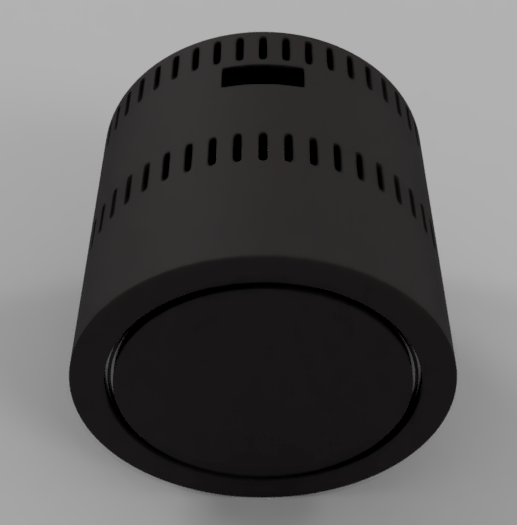
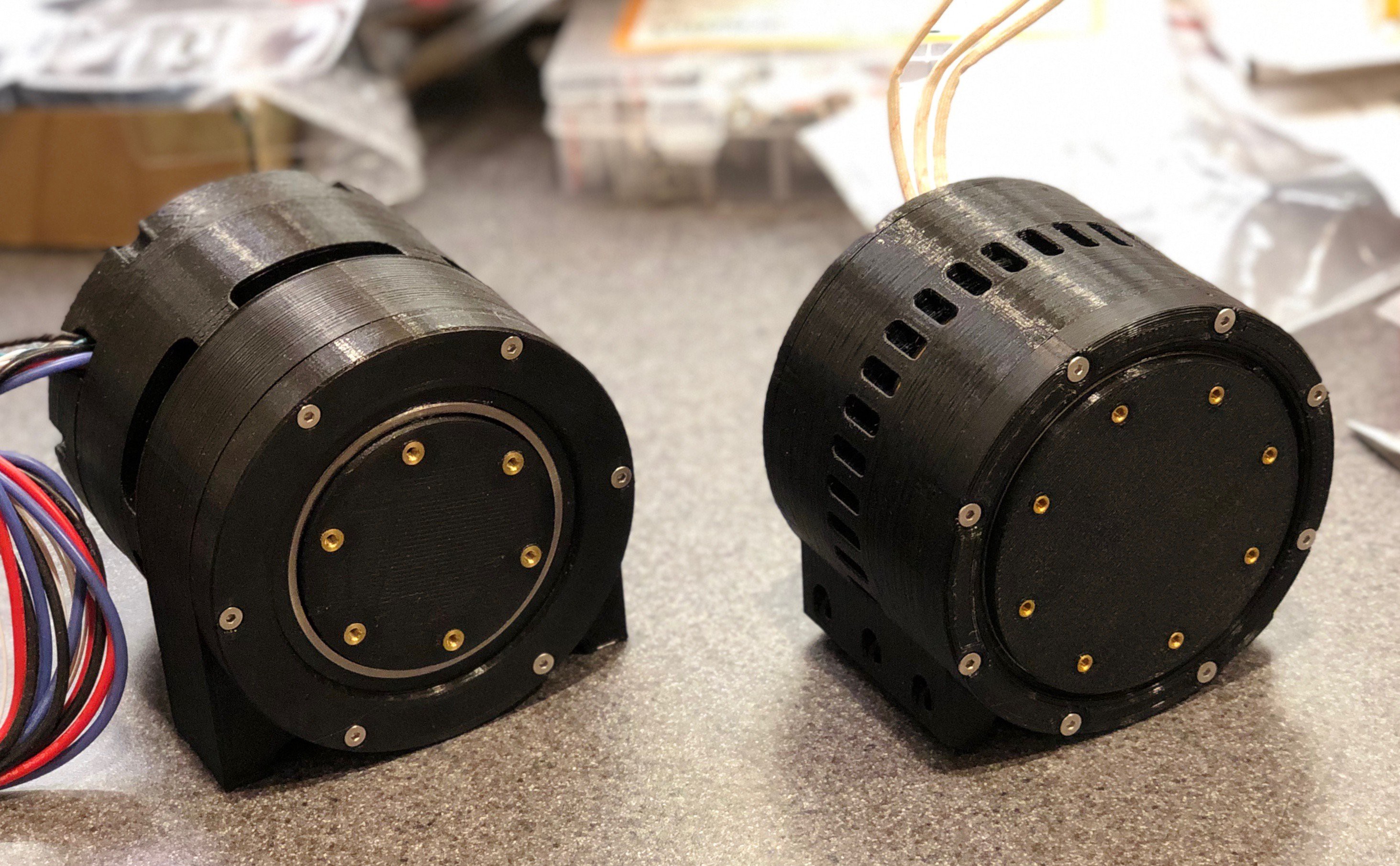
    V2 actuator on the right:

    The first OpenTorque v2 unit is built and working successfully, so I'm releasing the design files. You can get them at https://github.com/G-Levine/OpenTorque-Actuator. They're licensed under Creative Commons BY-SA 4.0, so feel free to modify them and use them in your own projects. 

    I'm currently prioritizing passive cooling because my walking robot will have a low duty cycle on the motors. As a result, this version is releasing with passive cooling only. Active air-cooling will come in a future update. I'd recommend it if you plan on building a robot arm, as the duty cycle on an arm is near 100%. 

    Other future updates will include support for the single-axis ODrive board (once it's released). This will allow daisy-chained power and data connections between actuators, greatly simplifying the wiring. 

  • OpenTorque v2

    Gabrael Levine11/17/2018 at 00:36 2 comments

    This is the new version of the OpenTorque actuator (still under development). I've made a number of design improvements:

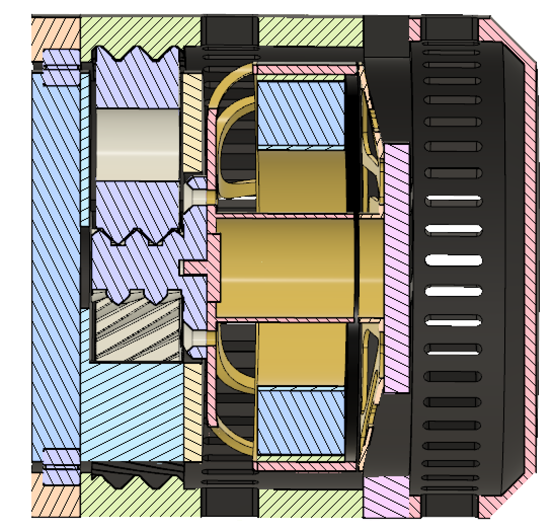
    • The two thin-section ball bearings are replaced by a single cross-roller bearing.
    • Better cooling. The GPU fan is replaced by a powerful 100mm centrifugal blower. 
    • Higher gear ratio of 8:1, for higher peak torque and reduced I2R losses under normal loads. 
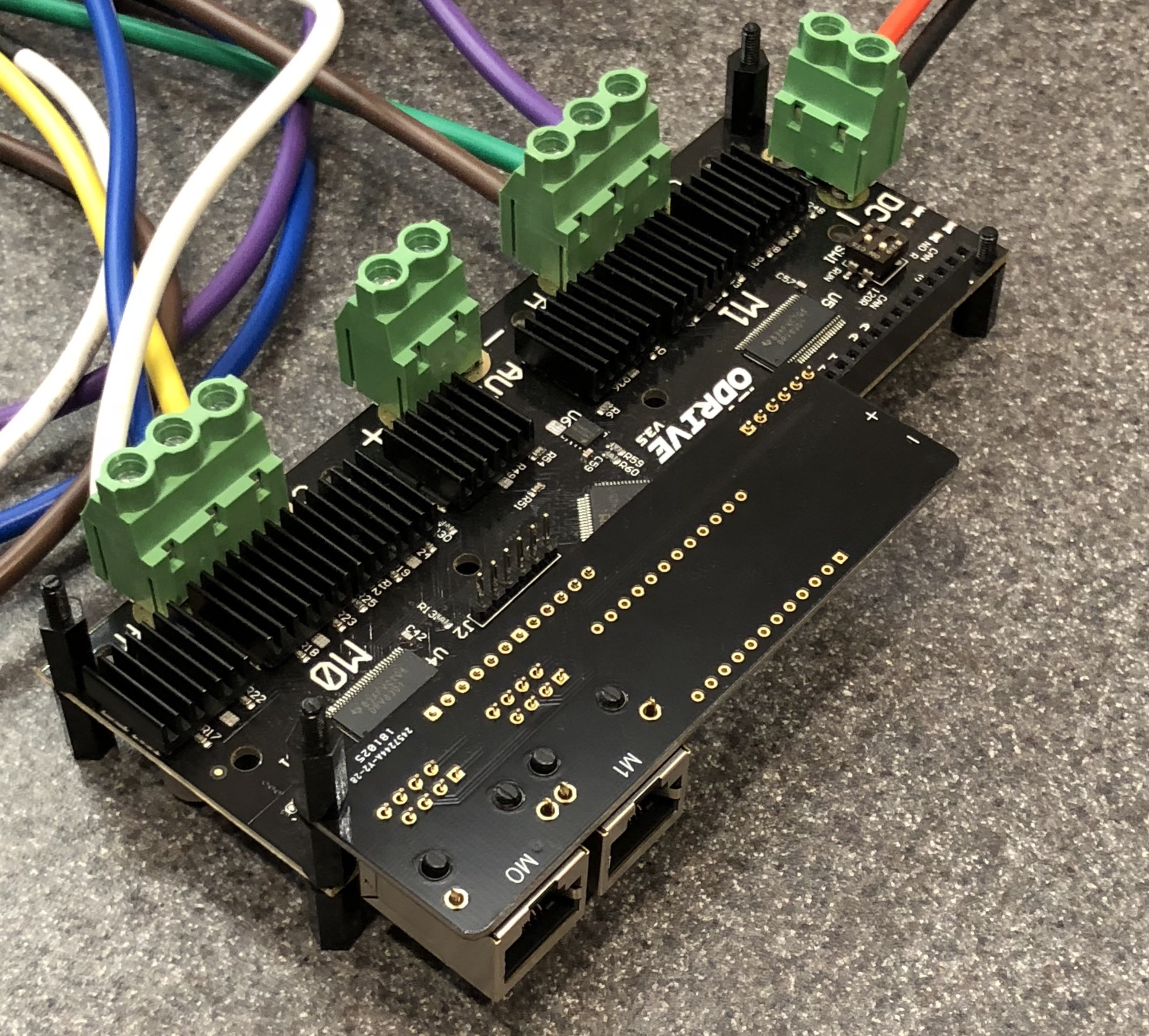
    • Custom PCB that breaks out the encoder SPI lines along with thermistor output and fan power to an RJ45 connector. This connects via a CAT7 patch cable to a custom daughterboard on the ODrive, pictured below. 
    • Lighter and more compact than the V1 actuator, and a closed back (no more exposed fan). 
    • Direct-drive version, in addition to the quasi-direct-drive version. 

    These improvements are aimed at making it easier to build systems with large numbers of OpenTorque actuators. I'm using the new actuator for my Blackbird Bipedal Robot but it's also well-suited for quadrupeds, robot arms, exoskeletons, and so forth. 

  • Thermal Testing

    Gabrael Levine07/25/2018 at 07:54 1 comment

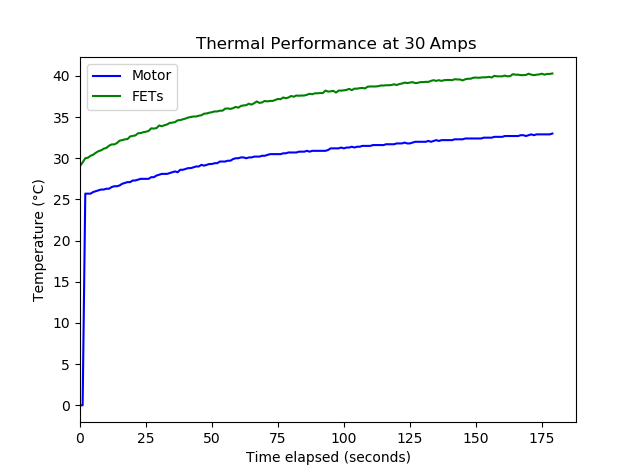
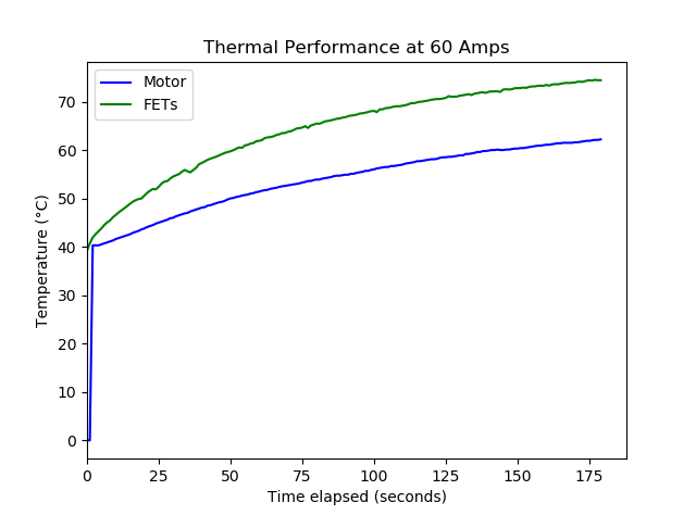
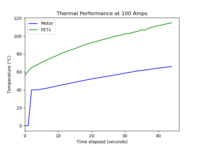
    I tested the thermal performance at 30A, 60A, and 100A. This was done by setting the calibration current to the desired level, then disconnecting the encoder and having the motor search for the index pulse. This results in the heat being evenly distributed among the 3 phases, as described here: https://discourse.odriverobotics.com/t/testing-forced-air-cooling-with-a-5060-motor/483. I collected data from a thermistor epoxied into the motor windings, and the built-in thermistor on the ODrive board. 

    Conclusions:

    • The motor cooling works quite well. Three minutes of sustained 60A current caused a temperature rise of less than 20 degrees. 
    • The FETs on the ODrive board heat up quickly. Currently I'm just cooling the board with a desk fan, so I'll have to design a more sophisticated cooling solution. 

  • Bipedal Robot Concept

    Gabrael Levine07/04/2018 at 04:11 0 comments

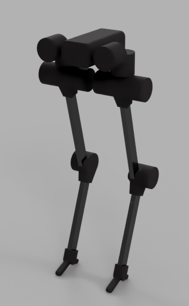
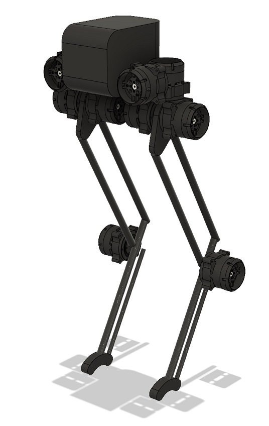
    I'm building a bipedal robot inspired by Agility Robotics' Cassie. It uses 10 OpenTorque actuators. 

    These actuators are backdrivable and able to absorb kinetic energy during the walk cycle. As a result of this, there's no need for the complex series-elastic linkages present in Cassie. Instead, each leg consists of a simple parallelogram linkage with an extra joint at the ankle. 

    Carbon fiber tubes are used for the linkages in order to keep inertia as low as possible. The total weight is in the ballpark of 30 pounds -- substantially lower than the 60-70 pounds that Cassie weighs. This is helped by the use of 3d-printed plastic rather than CNC aluminum parts. (All the structural parts will be printed out of NylonX.)

    To control this robot, I'm going to use reinforcement learning. I'll create an OpenAI training environment with a simulation of the robot, then let the controller learn a stable walking gait on its own. This is a lot easier than programming a walking gait by hand, and it's already been done successfully on the Minitaur robot. 

View all 4 project logs

  • 1
    Note: these instructions are for a previous version of OpenTorque. Go the the GitHub repo (https://github.com/G-Levine/OpenTorque-Actuator) for the latest instructions.
  • 2
    Print the parts
    • Use 50% infill and a wall thickness of at least 1.2 mm. 
    • Nylon is the recommended material for the sun and planet gears. I used Taulman Alloy 910. 
    • Print the planet gears on rafts to ensure the first layer comes out perfectly flat. Otherwise you can run into issues with the gears meshing. 
    • All the parts are designed to print without supports. 
  • 3
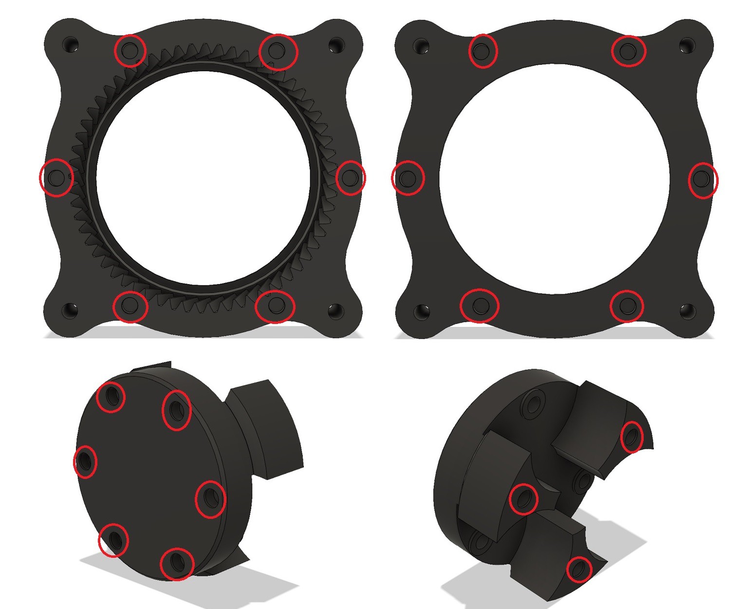
    Install the threaded inserts

    Printed parts:

    • Ring Gear
    • Planet Carrier Front

    Non-printed parts:

    • 21x M3 threaded inserts

    Instructions:

    1. Place the inserts in the holes (marked in red) and set them in place with a soldering iron. 

View all 8 instructions

Enjoy this project?

Share

Discussions

Sebastian Azcurra wrote 08/11/2020 at 13:58 point

Hello Gabrael, your project is really very interesting.

I am currently developing a project with a BLDC motor, and with an Odrive v3.5 controller, which I need to control the torque of the motor. To do some initial tests and get to know the Odrive controller, how can I program it to handle the torque control?
Thank you very much Gabrael and Congratulations!

  Are you sure? yes | no

Colton wrote 01/21/2020 at 04:20 point

Hi Gabrael, I'm new to this, but I work for another bio-mimicry lab and we were hoping to incorporate the OpenTorque actuator into some of our research. What methods have you been using to control the motor or the software involved?

  Are you sure? yes | no

saad wrote 11/27/2019 at 09:24 point

hello, what power supply do you use to test different A? have a link for the power supply?

thz Gabrael

  Are you sure? yes | no

Simon wrote 10/27/2019 at 13:34 point

Very nice project. How do you calculate a maximum torque of 80Nm? The manufacturer on Alibaba states a max torque of approx. 5Nm (no rpm given, but i assume it's the peak torque) so with a reduction of 8:1  40Nm  would be peak? What are your test results?  

  Are you sure? yes | no

Bree Hoffman wrote 10/09/2019 at 22:03 point

In your components you list the "THK RA8008 cross roller bearing" which are currently being sold for $150, but in your directions for assembly you denote the much cheaper "6813-2RS bearings".

I see the design improvements mention the THK RA8008 cross roller bearing being an upgrade component but the cost is enormous! Maybe we can make a version of v2 which continues to use the 6813-2RS bearings.

  Are you sure? yes | no

dave wrote 08/06/2019 at 17:35 point

Hey Gabrael, incredible work! I'm starting a print as I type this. Quick question, the large RA8008 bearing is quite expensive right now. Has the price just gone up since you designed this? Or was it always an expensive part? Any suggestions on the best place to purchase? Or is Alibaba it?

  Are you sure? yes | no

Bree Hoffman wrote 10/09/2019 at 22:11 point

Ah, you and I are noticing the same thing.

I bought a bunch of the other components before realizing this. I wish I'd made a cost spreadsheet first.

Maybe we can/should fork the repo and modify the design to revert back to the 6813-2RS's 

  Are you sure? yes | no

Scrungo-Beepis wrote 07/03/2019 at 15:53 point

Where did you get the model for that motor?

  Are you sure? yes | no

Igor Fabo wrote 03/25/2019 at 09:10 point

Hi, what type of microcontroller do you use for controlling odrive, the MIT Cheetah is using nucleo boards with mbed RTOS, what is your suggestion?

  Are you sure? yes | no

Gabrael Levine wrote 03/25/2019 at 18:15 point

Currently I’m using a Raspberry Pi with the preempt-rt patch. I’m planning to move to a Jetson Xavier later. 

  Are you sure? yes | no

Rob Menting wrote 03/23/2019 at 14:10 point

Hi Gabrael, for your force control you only use the current of the actuator or do you have some extra sensing ?

  Are you sure? yes | no

Gabrael Levine wrote 03/25/2019 at 18:16 point

Just the current. The gearbox is transparent enough that it doesn’t need any extra sensors for force control.

  Are you sure? yes | no

Charles wrote 02/08/2019 at 14:08 point

Ok, what kind of motor is used. Or are you making your own with electromagnetic coils? Also, how does this attach/what part of it turns? I am thinking to maybe use this same concept slightly modified for a wheel drive on a vehicle. I am thinking you could put this inside of an individual wheel, and it would drive itself.

  Are you sure? yes | no

Gabrael Levine wrote 02/15/2019 at 22:57 point

It uses an off-the-shelf brushless motor intended for heavy-lift quadcopters. 

The mounting points are on the actuator housing. The output turns with the planet carrier.  

  Are you sure? yes | no

Bruno Alfirević wrote 11/12/2018 at 02:30 point

Hey Gabrael, thanks for the great project! 

Regarding your comment about using cross-roller bearing to make the gearbox more compact - are those simply thinner or will you also be changing the design in a significant way?

  Are you sure? yes | no

Charles wrote 10/30/2018 at 04:19 point

could this possibly be thinned, so it is not as thick, and would fit better into exoskeletons?

  Are you sure? yes | no

Gabrael Levine wrote 10/30/2018 at 05:08 point

Yes, with steel gears. Hardened steel gears would be much thinner than plastic gears for the same load rating. They'd be heavier and add about $100 to the cost of each actuator, but if you want maximum compactness it would make sense to use them. 

  Are you sure? yes | no

Charles wrote 11/03/2018 at 00:25 point

How thin could it get, from the back to a half inch shaft extending from it?

  Are you sure? yes | no

Gabrael Levine wrote 11/03/2018 at 03:05 point

10 to 15mm thinner, depending on which gears you choose. The next version of the actuator will incorporate a cross-roller bearing, which will reduce the thickness by 10mm. 

  Are you sure? yes | no

anton.fosselius wrote 09/21/2018 at 06:22 point

This looks really awesome, this is exactly what i have wanted to do since i first saw Atrias and then Cassie. My only concern is the actuators on the knees, i know there is where the highest load are and it's very convenient to put the actuator directly on the joint. But this will have a BIG impact on the acceleration of the legs, more mass will have a big negative impact on how fast the legs can move from A to B. Have you tried to figure out a mechanical linkage to put the actuator for the knee at the hip level or at least as far from the feet as possible?

To quote Colin Chapman, if you want more speed  "Simplify, then add lightness”.

  Are you sure? yes | no

Gabrael Levine wrote 09/21/2018 at 06:57 point

The actuator on the knee isn’t for the knee, it’s connected to the ankle with a linkage. The torque requirements for the ankle are actually quite small (0 torque when the foot is on the ground), so it will be possible to use a much smaller motor there. 

The ankle actuator for the final design will either be a direct-drive 9235 motor (no gear reduction) or a 5008 motor with a 4:1 reduction.

  Are you sure? yes | no

anton.fosselius wrote 09/21/2018 at 07:17 point

Ok, great! also, just noted that i made the comment in the wrong project, sorry.
This is what we are discussing: https://hackaday.io/project/160882-blackbird-bipedal-robot

This image: https://cdn.hackaday.io/images/8728261530673941165.jpg

Now i see that its quite obvious that it is the ankle actuator that is placed on the knee.

  Are you sure? yes | no

Robin Fröjd wrote 08/09/2018 at 22:07 point

Very nice! I just order the motor so I can build one! :-) thanks for sharing!

  Are you sure? yes | no

David Shelenev wrote 07/20/2018 at 22:43 point

Hi Gabrael, your progress video seems really promising. I wanted to ask you, have you noticed any wear on the gears, or worsened backlash over time? I want to integrate your design into my robot arm project... I'm still tossing up whether to use a cycloidal direct drive design, or the OpenTorque actuator with a belt drive to the joint.

  Are you sure? yes | no

Gabrael Levine wrote 07/22/2018 at 00:42 point

I haven't noticed any wear or increased backlash on the gears. Just make sure to use nylon and not ABS. 

  Are you sure? yes | no

nick wrote 07/16/2018 at 12:23 point

this looks to have real potential, cant wait to see how it develops!

  Are you sure? yes | no

Similar Projects

Does this project spark your interest?

Become a member to follow this project and never miss any updates