Close
0%
0%

RR1: Real Robot One - Revision 2

The second revision of RR1, an open-source, 6+1 degrees of freedom desktop robotic arm, made mostly by 3D printing

Public Chat
Similar projects worth following
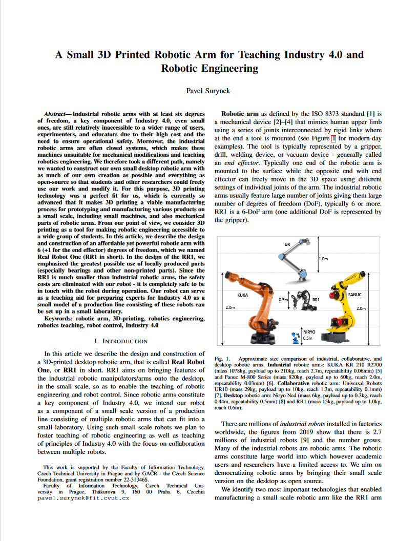
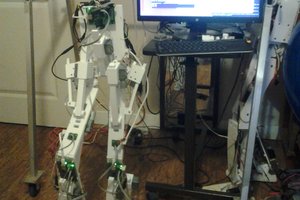
This is the second revision of the RR1 robotic arm (see the other project for the revision 1), RR1 rev. 2 in short. During the construction and operation of rev.1, I gained a lot of engineering experience, which I reflected in rev.2, having many improvements compared to rev.1. The second revision represents a very thorough redesign. I did improve everything I found not satisfactory in the previous robot. Again, I follow the mindset that I do not improve individual parts separately, but rather within the entire robot, i.e. I always build a complete robot with new parts and test it as a whole. A physical copy of rev.2 already exists as the photos show.

It is important to note that the robot is open source (both hardware and software), which I am trying to fulfill even more with rev.2, so everything I have created in connection with the robot is made freely available to the builder community, including the source CAD files.

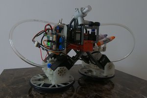
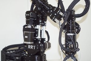
RR1 is a 3D-printed DIY desktop robotic arm. The overall design follows the idea of being able to produce more of these robots so that multi-robot coordination on the desktop is possible, obtaining a small scale Industry 4.0 on the table. RR1 features 6 degrees of freedom plus one degree of freedom for gripper altogether mimicking standard industrial robots but packed in small size. The robot features closed loop control with rotary encoders attached to each joint. RR1 is powered by 7 stepper motors (6 for axes and 1 for the gripper) that transfer torque to joints via 3D-printed split-ring planetary gearbox reducers. The revision 2 has many improvements against the revision 1 (the black robot) such as PCCF gears and encoders outside joints.

To enable full reproducibility, we provide everything as open-source including source CAD files (FreeCAD) here: https://github.com/surynek/RR1/tree/main/rev.2

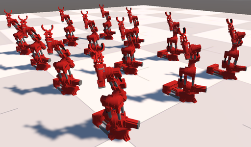
My collaborator Ján Chudý also made ROS-based control for RR1 and visualization of its digital twin in RVis and Unity, code here (repositories starting rr1_... and ros2-...): https://github.com/EnviloN?tab=repositories The software enables multi-robot simulation with multiple RR1s.
Here is a more detailed summary of the most important improvements that RR1 rev.2 brings:
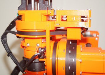
(1) The encoders for the individual joints are no longer on the shafts of the stepper motors, but directly on the joints, from which the torque is transmitted to the encoder by a belt (the GT2 6mm standard is used). From this change, we expect better sensitivity and the eventual possibility to compensate for the deflection within the arm. This change meant probably the biggest redesign, especially for the base turret, it was a challenge. But the overall design based on aluminum extrusions helped a lot, on which the encoder can be fixed and the belt can be easily tensioned by changing the position on the extrusion.
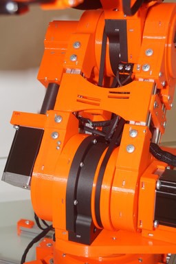

(2) Polycarbonate with carbon fiber (PCCF) is used instead of PETG for planetary gears and ring gears (the dark grey parts on the joints and everything inside is made of polycarbonate with carbon fiber). In rev.1 it was shown that PETG gears can deform or even break after intensive operation with loads (as I show in the video here). Polycarbonate with carbon fiber proved to be much better, it is a hard material, it feels like a stone, and also greatly reduced the backlash in the planetary gearboxes.
The video below shows how to calculate the reduction ratio of the split ring planetary gear box. It provides very deep insight in how this type of gearbox works. I recommend to watch the video carefully and calculate in sync with my commentary.


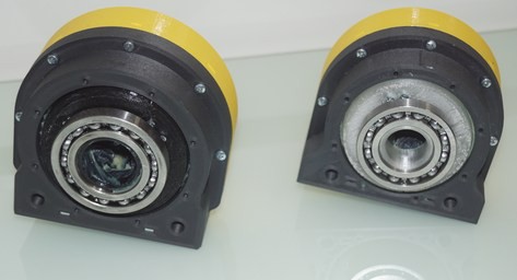
(3) Rev.2 uses the same type of split ring planetary gearboxes as rev.1, but they have larger ring gear diameters compared to rev.1, which greatly improves torque. New gears has larger teeth that mesh together better. Additional bearings are also used to improve the stability of the joints. The reduction ratio for large gearbox in the shoulder joint is approximately 1:40 which together with big Nema 23 motor (112mm in length) provides enough torque to lift the arm.
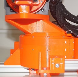
(4) The overall kinematic aspect was changed for RR1 rev.2. The arm has a base turret shifted a little forward, which improves the working space of the robot. The elbow link is further away from the elbow joint, which again improves the robot's dexterity and its working space. But mainly thanks to this, the robot can be folded into a compact form which makes it possible to put the robot in a standard large suitcase.
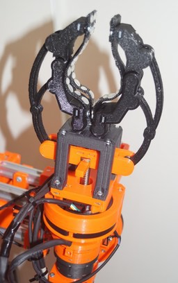
(5) The wrist has been completely redesigned, specifically the gripper is now attached both to the gearbox and also to another additional bearing that surrounds the motor of the gripper. This design greatly reduced the deflection of the gripper. The gripper itself has been redesigned. Compared to the rigid jaws in rev.1, rev.2 has jaws consisting of two links, which allows...

Read more »

  • 1 × Nema 23 Stepper motor 76mm for powering base (joint denoted J-S1, base yaw)
  • 1 × Nema 23 Stepper motor 112mm for powering big shoulder joint (joint denoted J-S2, shoulder pitch)
  • 1 × Nema 23 Stepper motor 80mm for powering elbow (joint denoted J-E1, elbow pitch)
  • 1 × Nema 23 Stepper motor 54mm for powering elbow (joint denoted J-E2, elbow roll)
  • 1 × Nema 17 Stepper motor 59mm for powering wrist (joint denoted J-W1, wrist pitch)

View all 15 components

  • Replacing the Elbow Joint on the RR1 rev. 2 Robotic Arm

    Pavel Surynek01/10/2025 at 18:01 0 comments

    I have a new video on the RR1 rev. 2 robotic arm. I show in the video how to replace the gearbox on the elbow joint. Since the gearbox is located practically in the middle of the robot, I have to disassemble and reassemble a lot. In addition to replacing the gearbox itself, the video shows a fairly significant part of the overall design of the RR1 robot and its assembly. The gearbox itself confirmed the hypothesis that the gearbox, or rather its main bearing of its own production, where steel balls are inserted between the printed rings with grooves (see one of the previous videos), does not run completely smoothly. The replacement gearbox uses a standard thin-walled bearing (61816 bearing, outer=100mm, inner=80mm, height=11mm) instead of my custom-built bearing. With the new gearbox, the movement of the robot in the elbow joint is much smoother, see for yourself at the end of the video!

  • 1:X? How to Calculate the Reduction Ratio of Split-Ring Planetary Gearbox

    Pavel Surynek10/14/2024 at 22:32 0 comments

    I advertise everywhere that the RR1 robotic arm uses split-ring planetary gearboxes that provide very high reduction ratio. But what is the theory behind these high numbers?

    The video below shows how to calculate the reduction ratio of the split ring planetary gear box. It provides very deep insight in how this type of gearbox works. I recommend to watch the video carefully and calculate in sync with my commentary.

    I believe the video explains where the high reduction ratios come from. English subtitles are provided.

  • A Paper on the RR1 Robotic Arm at IEEE CASE 2024

    Pavel Surynek09/21/2024 at 12:57 0 comments

    I am proud to share that my paper on the development of the RR1 robotic arm and its use in robotics education projects at my university has been published at the IEEE CASE 2024 conference in Bari, Italy.

    The paper briefly addresses the construction of the robot using 3D printing and the role of the robot in teaching of motion planning and multi-robot motion planning. Major focus of the paper is on building a concepts of Industry 4.0 consisting of small desktop robotic arms and other robots. Using small robotic arms enables to integrate everything in a small laboratory without additional safety measures that would be needed for large industrial robots. Integration of the RR1 robot in student projects is discussed as well.

    IEEE CASE 2024 is a flagship conference of the Robotic and Automation Society, the major international automation conference. This year the conference reached the milestone of 1000 attendees.

  • Gearbox Update for Shoulder and Elbow Joints

    Pavel Surynek07/25/2024 at 15:30 0 comments

    I have made a version of gearboxes for shoulder and elbow joints that feature thin wall bearings 61818 and 61816 respectively (sometimes denoted 6818 and 6816) instead of 3D-printed bearing with metal balls inserted between two grooves.

    CAD sources available in gihub here: https://github.com/surynek/RR1/tree/main/rev.2

    I expect smoother rotation from this update. However it means disassembling the current build of the robot and making the exchange.

View all 4 project logs

Enjoy this project?

Share

Discussions

Similar Projects

Does this project spark your interest?

Become a member to follow this project and never miss any updates