-
Open Source FTW
09/10/2019 at 08:44 • 0 commentsThere is so much joy in sharing projects and getting recognition for it (Portal Point Generator was a Hackaday Prize 2018 finalist). But what feels even more awesome, is the community actually taking up the project and realizing it for themselves, and to make the project even better.
This is the essence of Open Source community innovation.
When I started the project, with the plan to demonstrate it in Antarctica with 2041 (https://www.2041foundation.org/) , the intention was to create a story around the project to attract innovators from the community to build on the generator and make it better and move the needle on personalized power and giving people control of their own resources.
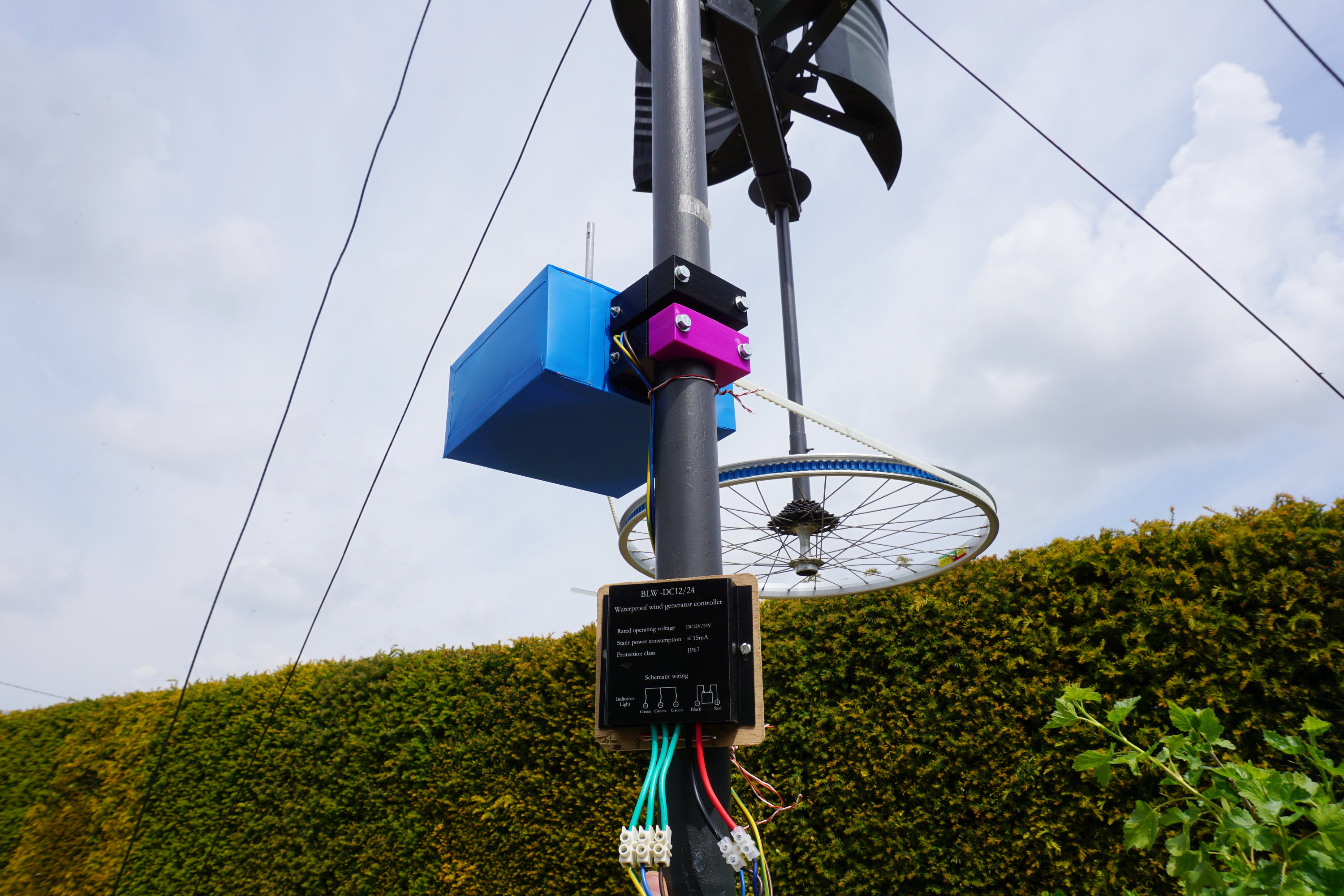
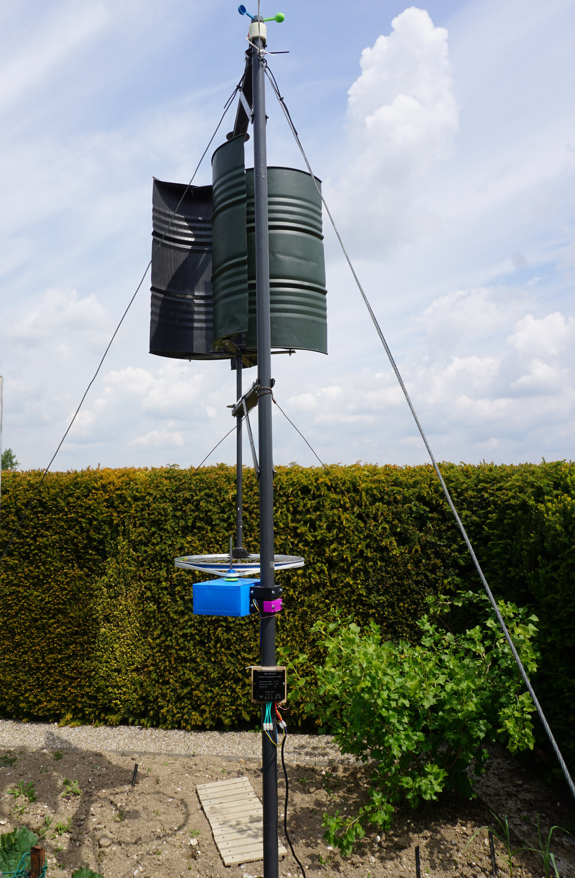
We are in the middle of a sea change in how electricity is generated, managed, distributed, stored, and consumed. New technologies in electricity generation, such as small-scale wind turbines, wave energy, and micro-harvesting are primed to bring electricity to places on the globe without access to reliable and affordable electricity. These new technologies bring with them opportunities in employment, healthcare, communication, and education.Thus, it was so heartening to see @MaKoTo realizing the generator and adapting and customizing it to his needs, and doing such a brilliant job and documenting his process, implementation and findings.

Above: The portal point generator with some slight modifications

Above: The final implementation, housed in a weather proof box, and a wind turbine charge controller
 Above: The pulley arrangement to experiment with various gearing ratios
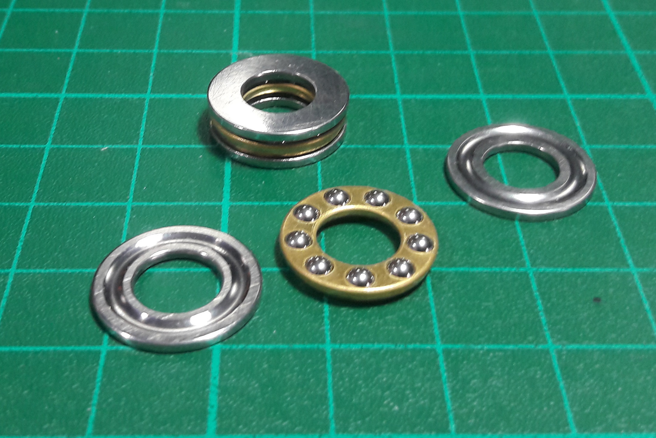
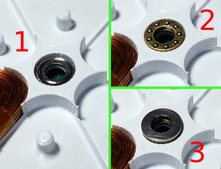
He even made some improvements with the bearings that I had planned for V2, in the current version itself that was one of the biggest flaws of the design.


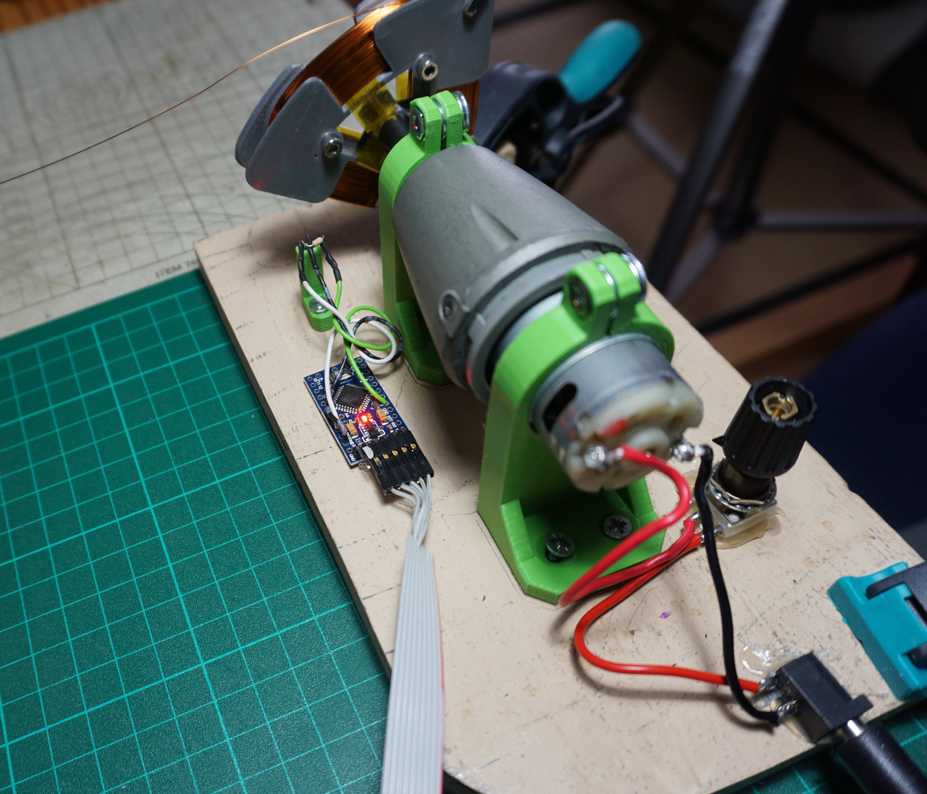
I'm very excited about the automated coil winding jig for precise winding of the stator coils ( Which I brute forced in a very "unscientific" way in V1). I secretly hoped someone if the community would make one, and I was overjoyed to see his implementation of it.

I was initially very apprehensive about anyone being able to recreate the project for themselves, owing to the complexity of the parts and assembly, but I feel much better now that there is more content out there to help people build on the project.
You can read about his entire process at:
https://burogu.makotoworkshop.org/index.php?post/2019/02/22/eolienne-axe-vertical-13
https://burogu.makotoworkshop.org/index.php?post/2019/05/15/eolienne-axe-vertical-15
Thigiverse links to the 3D Printable files:
https://www.thingiverse.com/thing:3675471
I'm inspired by this work, and look forward to implement some of his improvements in the next version of the turbine.
If you are working on the portal point generator yourself, do let me know, I'd love to give you a shutout and log it here!
-
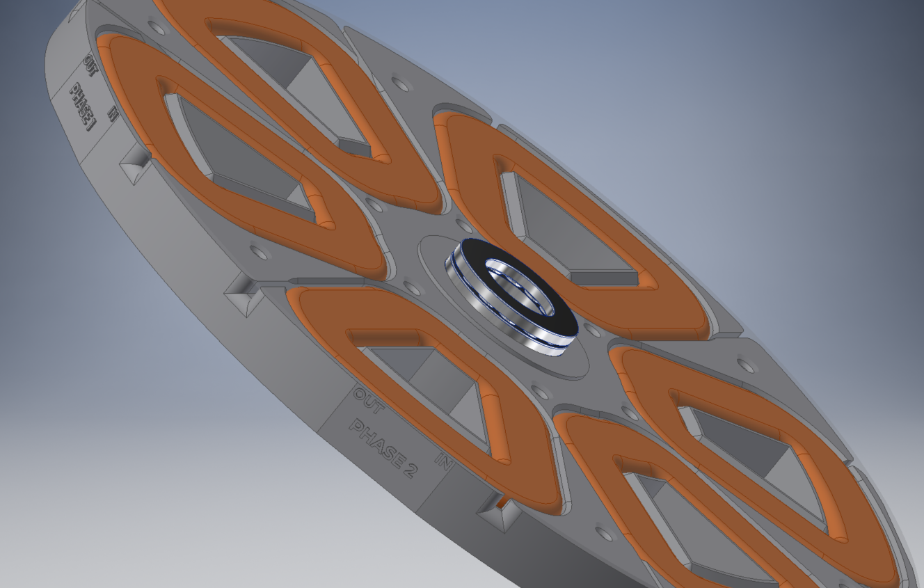
Stator V2
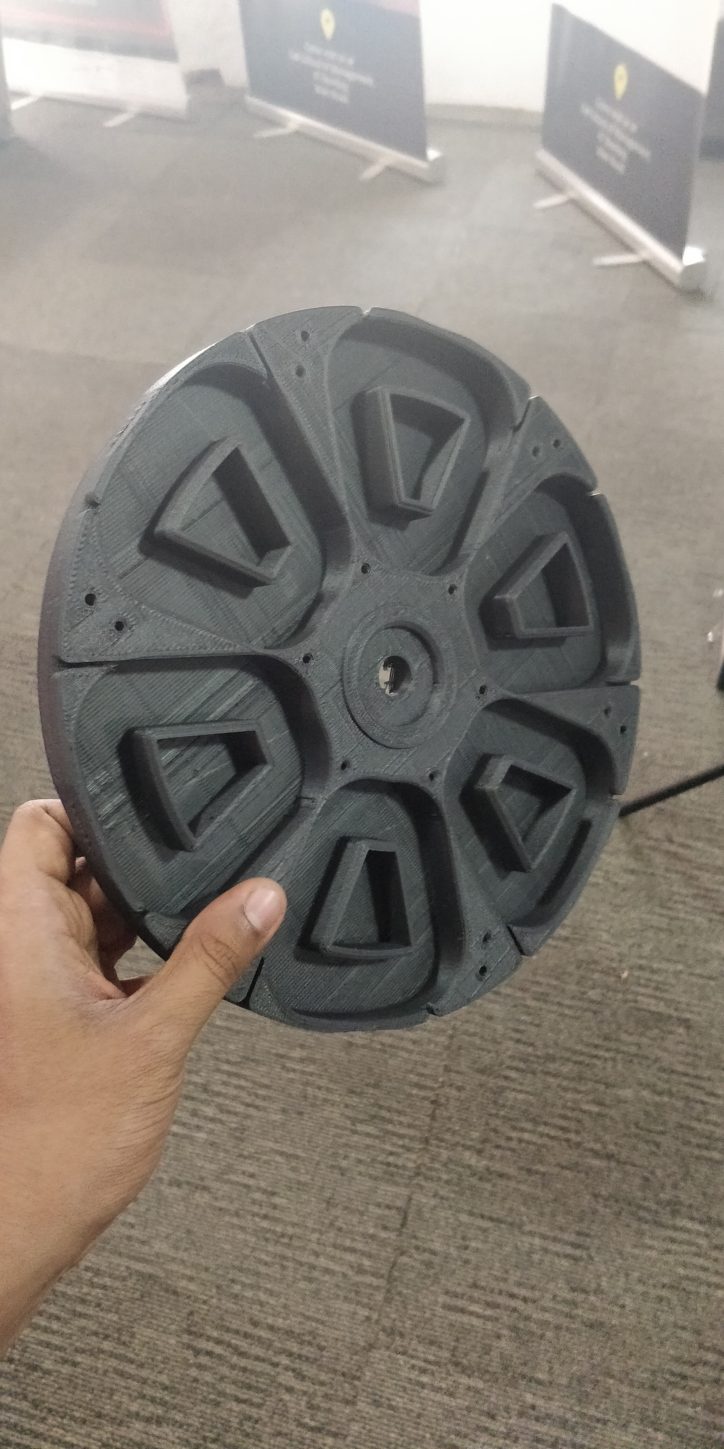
10/22/2018 at 10:12 • 2 commentsJust finished designing and 3D Printing the new Stator, which is one of the-most critical parts of the generator. It supports most of the weight of the stators that are heavy with the large magnets in them if the generator is placed vertically.
I did have some issues with V1, Where the stator would bend if the rotors were fastened incorrectly to the drive staft and hence improperly distributing the weight across the bearings.
V2 is waaaaay more stiffer, and is printed with Carbin Fiber ABS. The circular groove in the center is where the thrust bearing sits, which would make assembling the generator, especially dealing with the extremely strong magnets alot easier.
The stator itself if alot bigger than V2, since i'm gunning for atleast 500W with it. It fits on a printer with 250x250 bed size, but you may need to dissable the Skirt option.
-
Generator V2 Update
10/05/2018 at 17:03 • 0 comments Its time to go big or go home. Portal Point V2 is going to be a 500W generator, while still trying to be compact enough to fit on a commercially available 3D printer. I'm still using the same 40x20x10 N52 grade magnets, but increasing size of the coils.
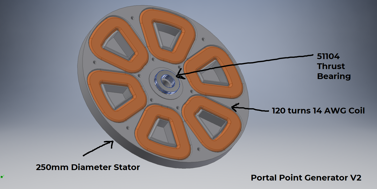
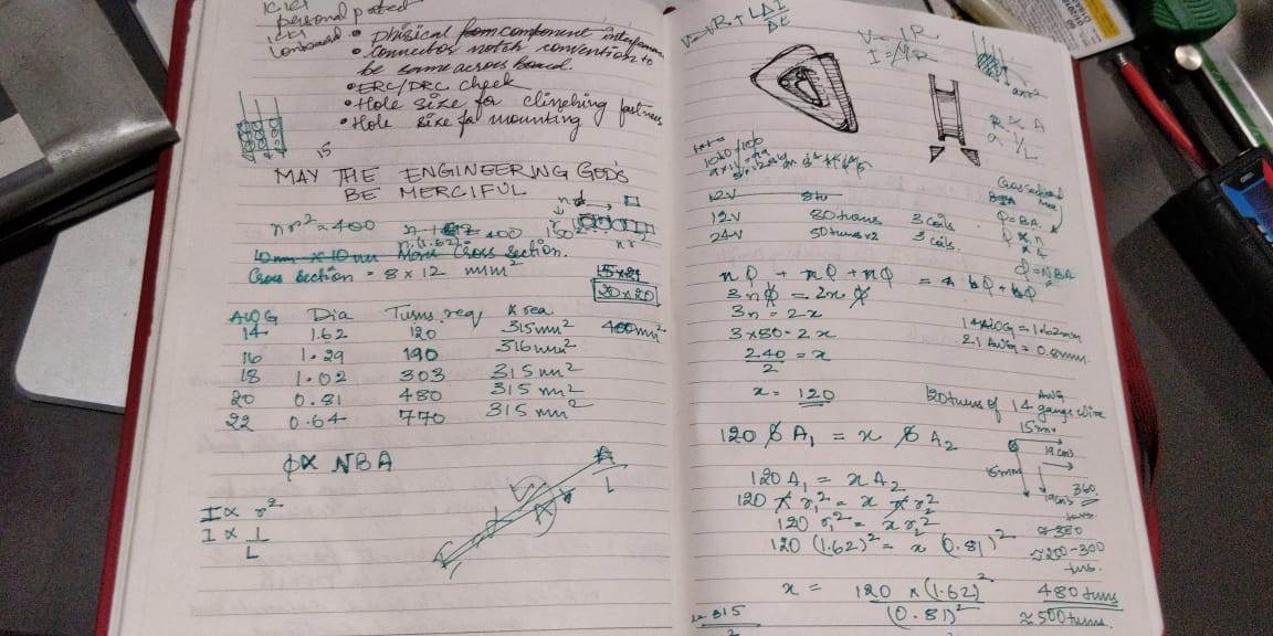
According to my ( very dirty ) calculations I need about 120 turns on 14 AWG copper, to keep resistive losses at a minimum. Ill explain the calculations later, but I'm working on the following assumptions to end up atleast at a 500W 12V generator:
1) Another 3 phase generator, that uses 3 coils instead of 2 per phase claimed 800W 12V using 14 AWG wire of 80 turns. it used slightly larger 52 grade magnets
2) To determine the optimum packing, area of the coil etc, I approximated the of the wire to be a square of side equal to the diameter, so i have a size I can start CAD modelling with. I didn't no any other calculations other than that with this approximation
With that, I came down to a coil of 120 Turns, and a stator of diameter 250mm which can house 2 coils per phase.
I decided to use a couple of thrust bearings to keep the distance between the rotor and stator constant, that differ from the previous design that can to be fastened to the drive shaft to maintain proper clearance. It was a pain to assemble.I'm looking at DFA as a side goal for this version.

I labeled the coils as well, so i'm sure of the wiring.
-
From Asia to Antarctica : Worlds first 3D Printed wind turbine in Antarctica
10/03/2018 at 05:59 • 0 commentsI was lucky enough to get documented as a part of the efforts of a film crew during the expedition to Antarctica, with others who have made fighting climate change their life's mission. I come up somewhere towards the end, but the entire short documentary is worth the watch beginning to end.
-
Generator Optimization
08/23/2018 at 13:27 • 0 commentsWith the one version done and tested, I wanted to address and fix some of the design and construction issues I faced while building and designing version one. The following are the list of changes I am aiming for:
1) Rotor Assembly
Assembling the rotor was literally a bloody nightmare resulting in cuts and bruises from shattered magnets flying all over the place. The rotor will be modified to aid easier assembly
2) Stator rigidity
Owing to the weight of the stater assembly with the large number of magnets, the stater began to show signs of fatigue after a few days of continuous use ( When kept in vertical position). A large amount of weight from the heavy rotors were being concentrated at the center of the stator. I will be beefing up the stator with ribs, and redesigning the casing such that it takes away the loading from the stator as much as possible.
3) Coil Winding Rig
A coil winding rig with a arduino and encoder which can repeatably reproduce the number of coils on the stator winding's
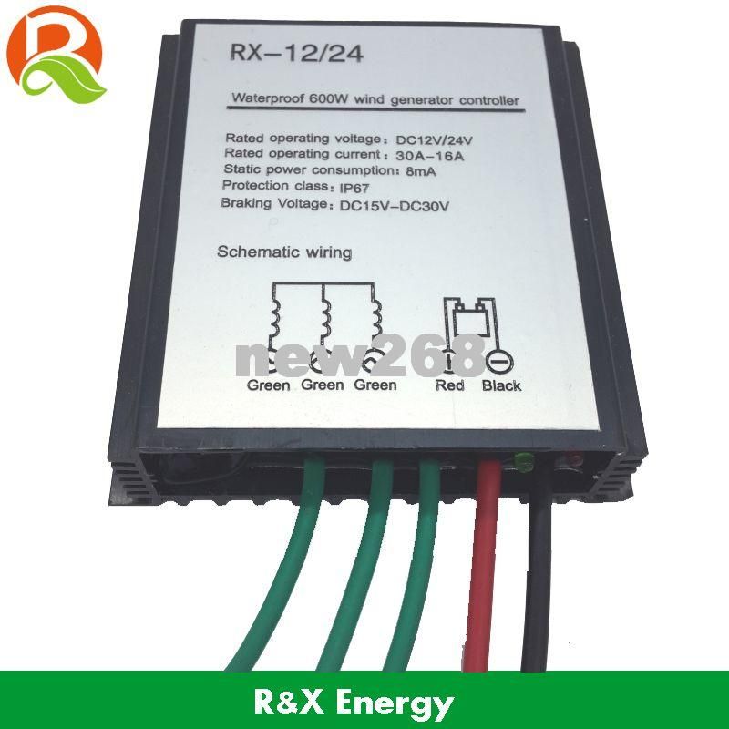
4) Using a Wind Turbine Charge Controller
I had used a buck converter with a bridge rectifier initially which did the job of charging a phone, but I think its not the best way to do things. For one, there is no over-speed protection which shunts the output of the turbine to prevent it spinning wildly out of control in case of a storm or something.

So I ordered this relatively cheap wind turbine charge controller. I'm still unsure what wizardry is going on inside it, but hope it does a better job than a buck regulator.
-
Voltage Output
08/06/2018 at 06:33 • 0 commentsI peaked the voltage output at about 75V with a drilling machine before I screwed up my multi-meter, probably by going over its rated current, but it was producing a cool 24V from a ceiling fan.
I was able to step down the voltage using a buck regulator and charge things, but think I would need to Charge Controller of sorts to better regulate the voltages and give a decent amount of current, especially if the voltages peaks go above 40V which would damage the buck converter. -
Rotors
07/15/2018 at 15:43 • 0 commentsThe picture below shows of the rotor stacks up into an assembly. The magnets get embedded into the magnet housing, and is covered by a laser cut sheet metal cover. The sheet metal cover prevents magnetic flux of the powerful magnets from going out of the generator, and also makes the flux stronger on one side of the Magnets.
The rotor brace prevents the powerful magnets from collapsing into each other ( THE MAGNETS ARE FREGGIN POWERFUL), as well as provides a way to mount the drive shaft. Use M3x16 CSK screws to mount everything together.
-
Star Topology Arrangement
07/15/2018 at 15:34 • 0 commentsConnect the phases in a delta pattern. There are 2 Coils for each phase. The coil on the opposite sides are of a single phase.
Connection coils of the same phase in series first, the "OUT" of the first coil with the "IN" of the second coil of the same phase.
Then connect all the remaining "IN"s of the three phases together which would be the common ground. All the "OUT"s will be the three phase output.
In the below images, I covered the coils with the stater cover, and marked the IN's and OUT's of the coils to aid wiring.
removed the enamel from the ends of the wires with sand paper:
(My desk is messy, i know)
-
Stator Assembly
07/14/2018 at 11:23 • 0 commentsCoil Placement:
Place the coils inside the Coil Holder/ Stator. There are three pins inside which the coils will sit.
The "IN" and "OUT" of the coils where the winding started and ended need to the placed in the appropriate notches. These will help identify how the coils would be wound.
Coil Housing Preparation:
Glue gun the coils in place.
 Apply glue to the edges of the coil housing
 The coil housing is covered with the 3DP Housing Cover
-
Assembly Process: Jig Preparation + Coiling
07/13/2018 at 13:59 • 0 commentsJig Preparation:
The winding jig is used to wind the coil. The Jig and the Jig holder are fastened together using M3 fasteners.
 Print 2 Jigs, fix them along their shape, and elevations facing each other.
 Attach the 3DP Jig Holder on one of the faces. I recommend marking this face, and you should use the same convention when winding all the coils., and the winding direction should match.
  There is a small hole in the jig through which you can slot the wire, to keep it in place while winding. Put the 30 AWG wire into this from the inside of the jig, coming out.
 Attach kapton tape in the 3 slots . Once the coiling is done, the kapton will be folded onto the finished coil to hold its shape.
Coil Preparation:
The jig is mounted on a power screw driver/drilling machine using a HEX bit. There is a notch on the jig to indicate when the maximum number of coils are reached.
Try and maintain a constant level of tension on the coils to get a roughly same number of coils. 6 coils will need to me made like this.
Use kapton tape to keep the cool from unwinding. Keep the kapton in place on the inside of the coil, and wind on top of it.
There is a hole on the jig where the start of the coil is placed. As long as you use the same convention for winding, and placing into the coil holder, you should be alright, only the polarity of the DC would change.
To Do: Automate this process with a encoder and counter to be more accurate.

If you have the patience, you can hold the handle and wind by hand, or use a drill/power driver to make this faster. You need 6 coils.

Fold the Kapton tape over the coil to hold it in place. Now work backwards to remove the coil.
Portal Point Generator
An efficient and compact generator that can be coupled with wind turbines or water wheels to produce upwards of 100W
 Vijay
Vijay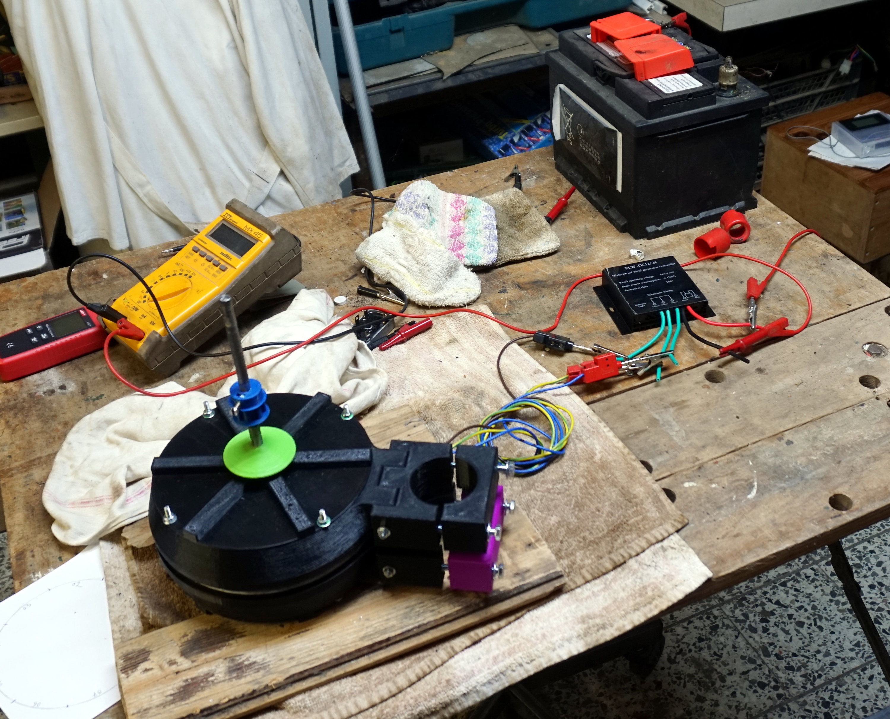


_gPtyCD81JT.png?auto=compress%2Cformat&w=1280&h=960&fit=max)
_TsuPVNgsSW.png?auto=compress%2Cformat&w=1280&h=960&fit=max)
_RhjUExTi51.png?auto=compress%2Cformat&w=1280&h=960&fit=max)
_najiqEG8nD.png?auto=compress%2Cformat&w=1280&h=960&fit=max)
_xBVzEU8Otz.png?auto=compress%2Cformat&w=1280&h=960&fit=max)
_v16UN1AW8b.png?auto=compress%2Cformat&w=1280&h=960&fit=max)
_0hSwigP329.png?auto=compress%2Cformat&w=1280&h=960&fit=max)
_B5iVHpUuD4.png?auto=compress%2Cformat&w=1280&h=960&fit=max)
_pLHxkTCzky.png?auto=compress%2Cformat&w=1280&h=960&fit=max)
_Y8ooqtIZsr.png?auto=compress%2Cformat&w=1280&h=960&fit=max)
_2fSisZZSVH.png?auto=compress%2Cformat&w=1280&h=960&fit=max)
_UEhPOKnZNZ.png?auto=compress%2Cformat&w=1280&h=960&fit=max)
_bx1YKT175O.png?auto=compress%2Cformat&w=1280&h=960&fit=max)
_xfxS2GKSAm.png?auto=compress%2Cformat&w=1280&h=960&fit=max)
_NWNsIPfduO.png?auto=compress%2Cformat&w=1280&h=960&fit=max)