MasterOfNull
-
Slip sliding away
07/31/2018 at 09:52 • 0 commentsI blew away the previous tweaks I had done for the slip fit on the OD of the bearing, so I've done a bit of iteration getting it back. Done.
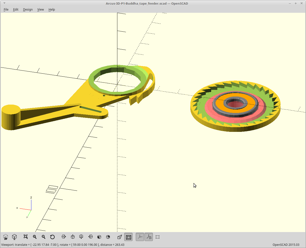
Even so, the cover drive sprocket was feeling a bit wimpy and flexing too much, so I stole some height back from the lever arm. The pink bit is new.
![]()
Printing again.
-
Snazzy.
07/31/2018 at 00:47 • 0 commentsI was inspired to try the animation feature of OpenSCAD. I've been using it for years, but just never did that.
Here is the variable rate between the two sprockets visualized.
Pretty snazzy..
-
Humanly possible.
07/30/2018 at 20:59 • 0 commentsI simplified things so the right thing happens when you uncomment each part for printing by default now.
Also got rid of a bunch of stray numbers making up for more math I didn't do right. Source has been updated.
Now, I want to change it all again, but I'm resisting the urge for now.
I think I could implement having the cover tape spool to be a 'drop in from the top' sort of deal. Having it be how it is once these are all mounted would be rather inconvenient.
-
Work, until it works..
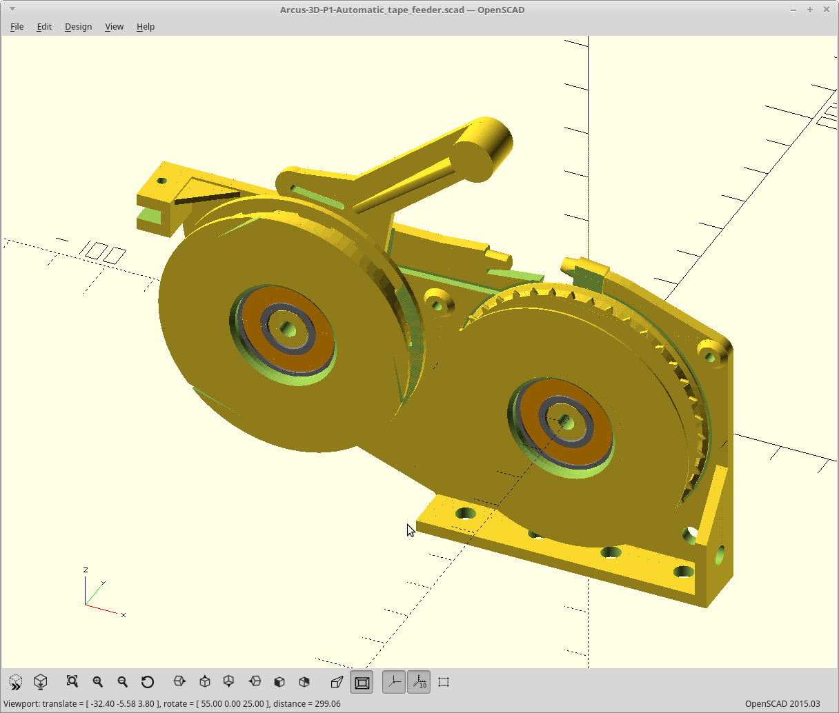
07/30/2018 at 14:15 • 0 comments![]()
Moved the cover spool down to flush with the drive spool.
Went from using a pushrod to a pull, which I'm much happier about.
Changed from a binder clip to a pen spring, and it's now on the drive pulley ratchet instead.
Tweaked the gear ratios and ratchet positions so each lever push locks at the next ratchet position at 2/3rds throw, so anything more than 2/3rds is still one advancement.Added servo support. You should be able to run two of these with one servo.
Maintained the ability to change the cover spool direction in code, and you only need to reprint 2 parts.
I settled on 12mm width. It was a lot easier to make it strong enough supported from one side that way. If you are stacking them, you can go back to 11.5 or even 11mm.![]()
Source has been updated.
Printing again...
-
Scaling
07/29/2018 at 20:06 • 0 commentsFinished printing it out, and it needs some work.
I reduced the size of the lever arm ratchet for this one, but the scaled ratchet doesn't perform nearly as well as the older version. It's sticky. The bending portion doesn't scale as it's based on the nozzle_dia, so it was too thick.
Making the cover tape spool deeper required splitting it into two parts as well, and they don't mate properly.
The return spring is a bit strong still, and I didn't make the throw long enough.
I also lost some of my tweaked dimensions such as the clutch and bearing interfaces in the process of realizing the fully parametric version. so they are too tight/too loose.
Working on it.
-
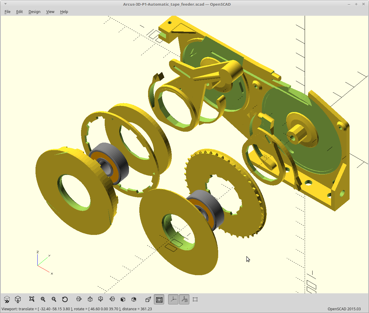
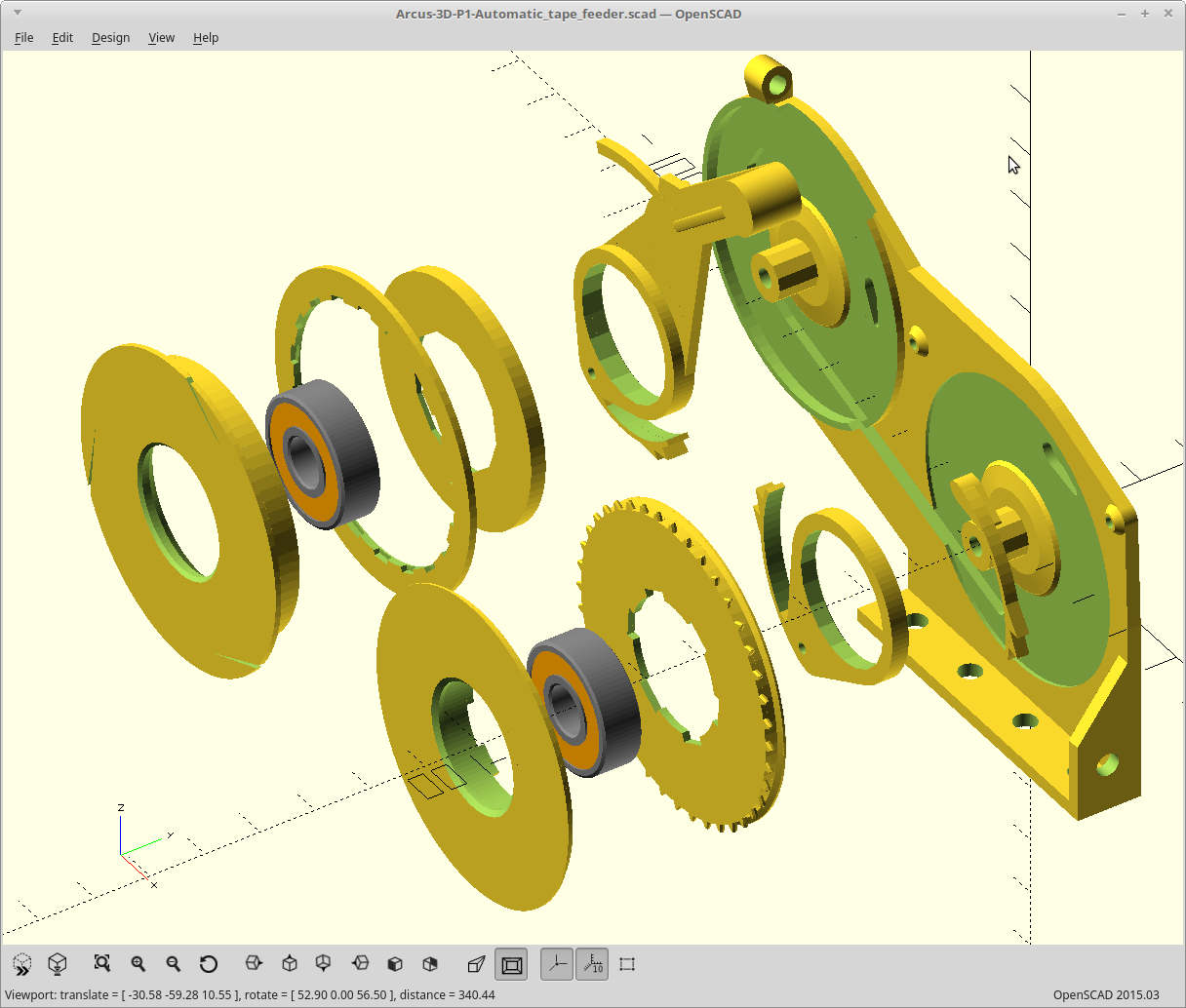
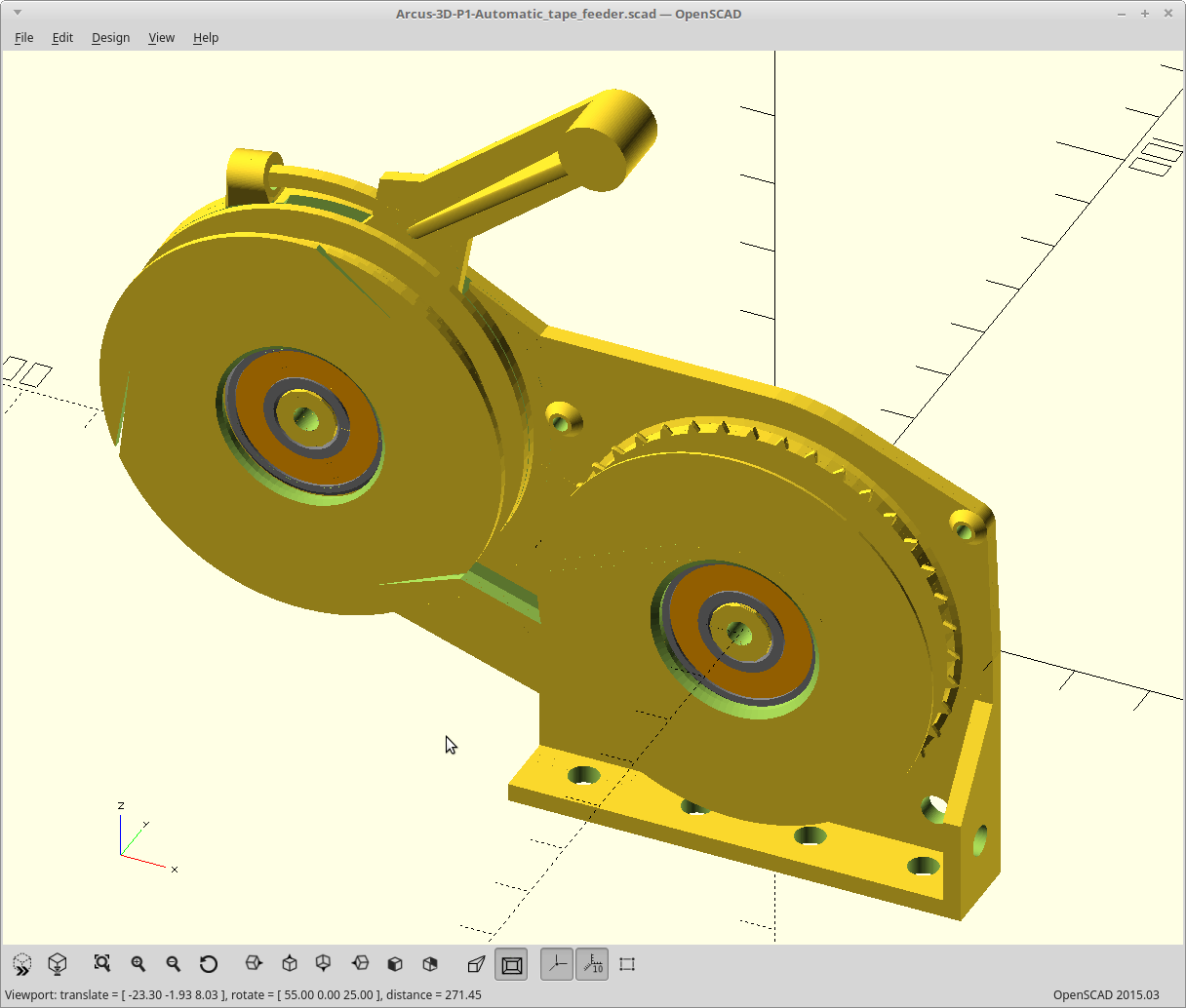
Parametric!
07/29/2018 at 01:15 • 0 commentsReworked all the code so you can change the offsets, gear ratios, sprocket and ratchet tooth count, thickness, and even the cover spool direction on the fly and everything scales.
![]()
I also moved the return spring up to the lever handle, and changed the connecting rod to be piano wire.
The whole thing is a lot sturdier, but I gained .5mm of thickness in the process and we are now at <tape width> + 4mm,. Good thing is now, if you want, you could just turn that down as a variable. :)
![]()
I've uploaded the updated source.
Time to print this thing again.
-
The show must go on.
07/28/2018 at 12:05 • 0 commentsI've ended up putting some serious time into fixing my parametric errors in this model before starting the new one.
It's getting pretty close... I'll put it up again once everything scales and shifts correctly.
I also realized another way to reduce the cover tape reel size a little, which I'm implementing.
-
Make up your mind..
07/27/2018 at 20:39 • 0 commentsI can't help but read the title with some serious reverse reverb.
Another foray into my subconscious, another competing idea...
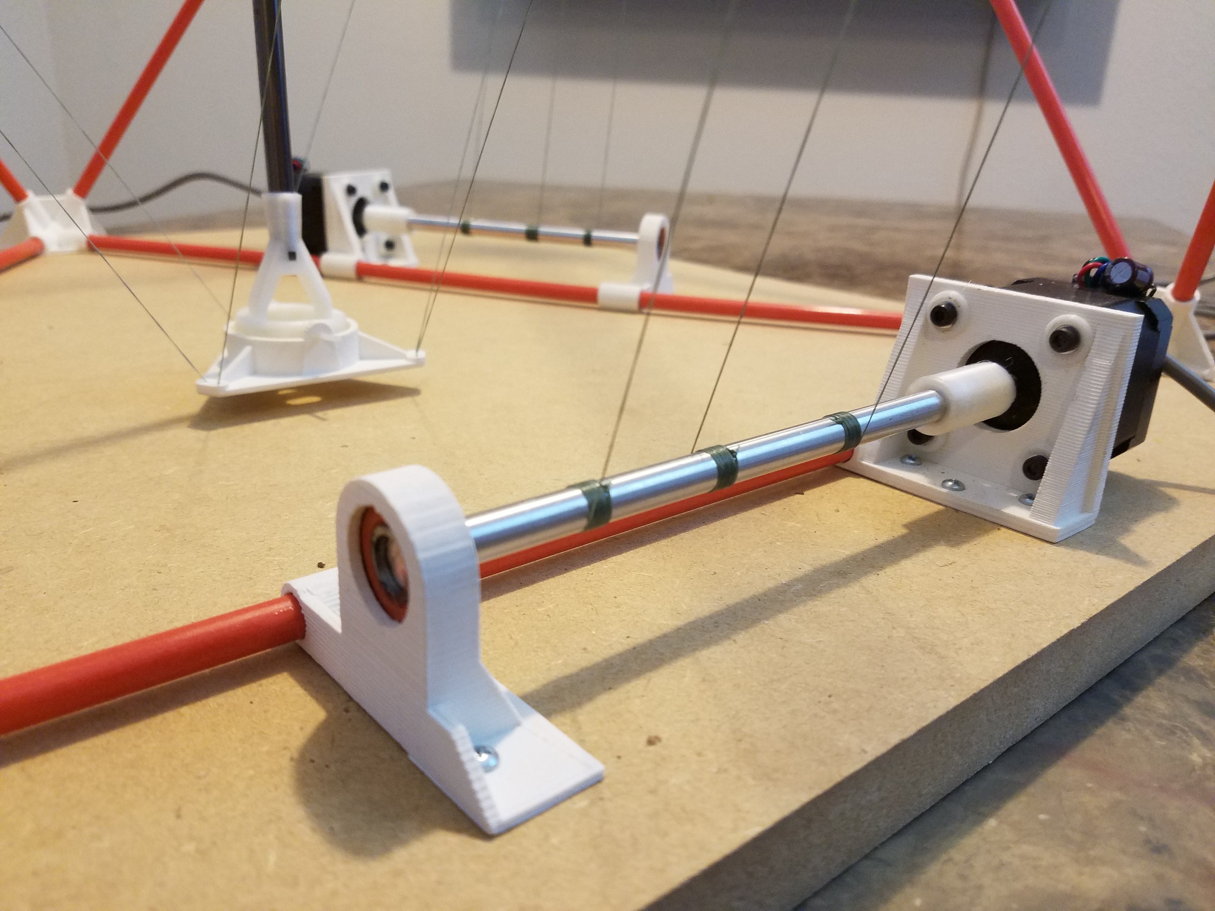
I've been thinking about my application here and my targeted motion platform, the C1.
![]()
Fast and accurate for a small area, as long as you don't load the head. Well, a lever actuated semi-automatic feeder is going to do just that. If I had a larger area to work with, I could just extend the lever for more force, but I don't.
So I think I've changed my mind and I'm going to add a servo, and fork this project to make that one. I think this idea still has merit, just not when the P1 is going to be used with the C1.
I'll swap the lever for a thin wire connecting rod with a long U shaped loop at the end. A screw in the loop from the horn of the servo will pull it. The loop lets me run two of these per servo, with the servo mounted spanning two units.
I think I'll also swap the binder clip for a pen spring, probably coaxial on the connecting rod itself.
I'll put the source up as it was, scaling issues and all, and move on for now.
-
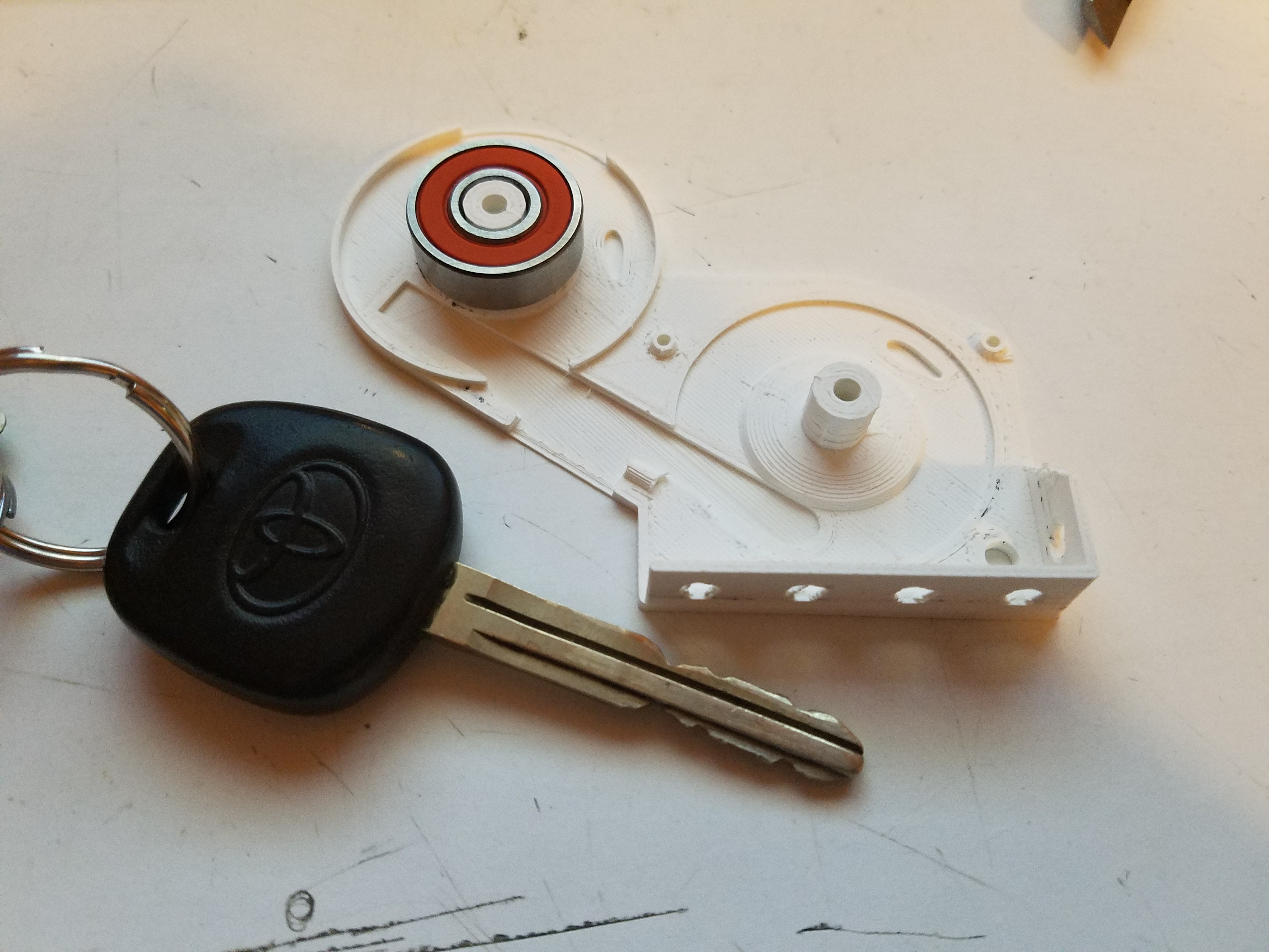
Objects in mirror..
07/27/2018 at 05:52 • 0 commentsWell, it's small. Too small. I thought that skateboard bearing looked huge...
![]()
I had messed with the number of teeth on the drive sprocket earlier. The design is parametric so the tooth count, being bound to the fixed parameter of the tape hole interval, scaled. Max part depth is somewhere around 4mm right now.
Not all of my math in OpenSCAD was done correctly, so not everything scaled correctly when I put it back. I go through cycles of just trying numbers, and then figuring out the math to produce them and some of that hard coded stuff stuck.
I have some work to do still. Math... I'm taking a break and will be back at it this weekend.
-
Ratchet, no Clank.
07/27/2018 at 04:20 • 0 commentsHere's the 3D printed ratchet I dreamed up.
Basically the whole thing is based around this.
P1 - Buddha Tape feeder
3D printable Pick and Place tape feeder for the Arcus-3D-P1.