Maximiliano Rojas
-
Stage 10 - version 0.1 and further development
08/23/2018 at 05:07 • 0 commentsAt this point, I must decide between two pasts, officially announce the version V0.1 and improve the system (bug correction and more surprises) or develop more modules, so, as you can guess the version V0.1 is officially announced.
Due that I don't have a lot of time these weeks I hope that the community report bugs to correct them, but in my free time (and when I resolve significant bugs) I will update the programs, equations, and structures.
Least, but not less important, I want to incorporate several new improves and characteristic, like structure modification for specific task or fields of study (like surgery, or robot control).
Any suggest will be welcome.
But first I must approve my exams, so you must wait a little.
-
Stage 9 - How to implement it in other projects
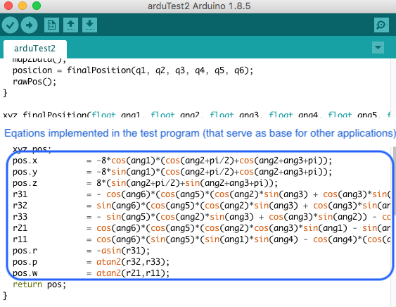
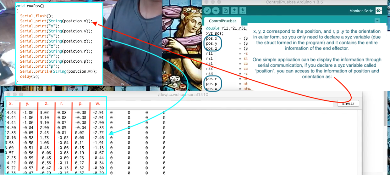
08/23/2018 at 05:06 • 0 commentsI guess that the main problem is to implement the mathematical equations, this is easy to clarify because you already have the equations in the programs like "ControlTestV2.ino" where are the new equations for the position and orientation acquisition system, so you don't need to rewrite them or even understand'em, just use the function design to simplify your life (and project):
![]()
![]()
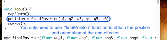
q(n) are the angles measured by the potentiometers, the index (n) of these angles are related of the position of these sensors, for more details, you can read "Stage 1", then, in the example program:
![]()
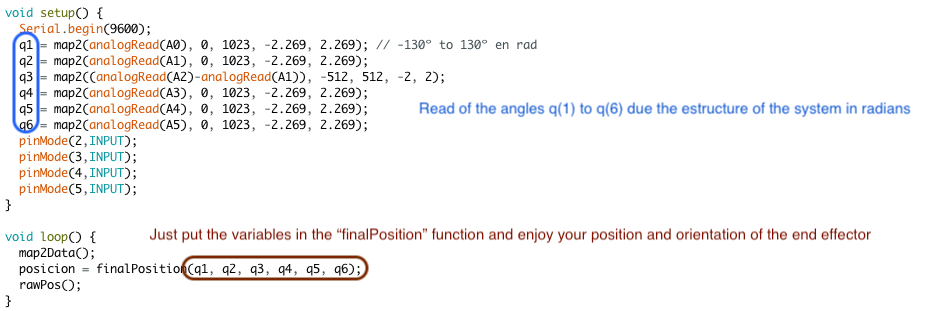
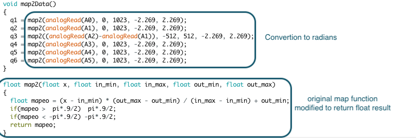
The other function has these purpose:
![]()
The simplest application example:
![]()
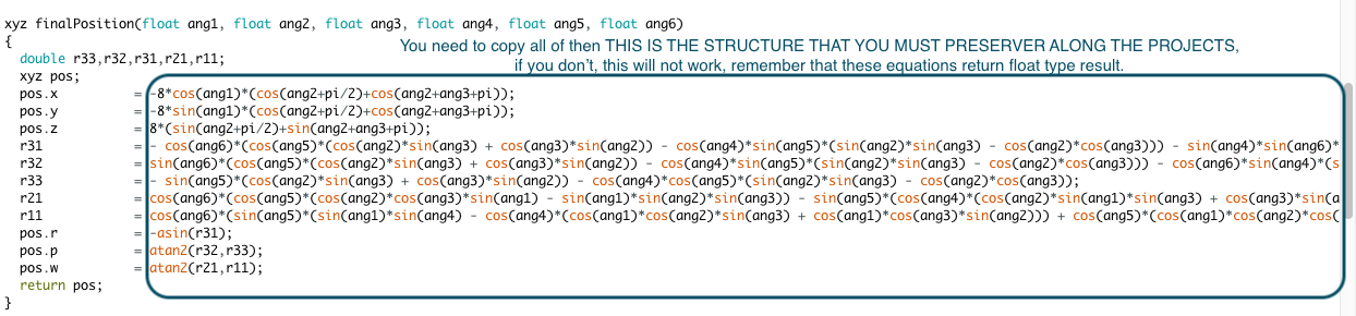
But ¿If you want to use it in other language program or something like that? Don't worry, the "finalPosition" function has the equations! so just copy that (if the syntax are similar) or just copy the equations and put'em in your new variables:
![]()
"Ok, but I only want to use a module of my creation". I can't be happier, you can start to program your module for been use with my system with the example program "ControlTestV2.ino", the way of creating a module depends on your idea for it, but you can be guided with the stages corresponding to module creation like "wolfverine", "test module" and "delta robot module".
Please, if you have any doubt, post it in the comments.
-
Stage 8 - Test in Unity of wolfverine module
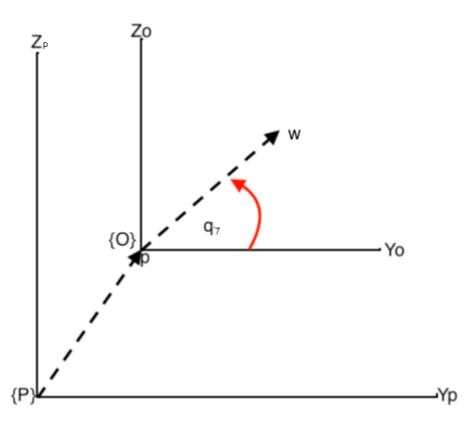
08/18/2018 at 06:46 • 0 commentsIs necessary obtain the equations that describe the position and orientation of the moving part of this module with respect to the base of the arm. We can start from the end effector because we already have the matrix that describes the arm structure, so, we only need to find the final position of the moving part with respect to the end effector (only position, because the orientation is not influenced by this, besides is the same in both cases). Is propper build two frames of reference:
![]()
Where {P} is the frame of reference for the end effector, {O} is for the moving part, p is the position of the end effector in {P}, and w is the position of the moving part in {O}, then:
![]()
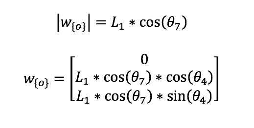
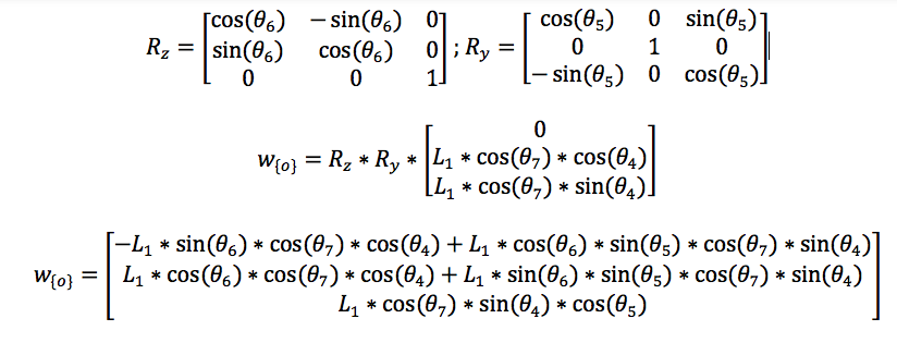
Considering the rotation of the end effector:
![]()
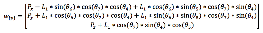
To obtain w with respect {P} we just sum the components of p, so:
![]()
The end effector and moving part has the same rotation. A vídeo that show the test is:
-
Stage 7 - Constant Current Circuit
08/18/2018 at 03:00 • 0 commentsThe main purpose of this stage is to show a circuit that can regulate the current flow to a constant value, besides it can be energized by batteries. that can be recharged.
I'll use the L7805CV voltage regulator, the datasheet is here:
https://www.mouser.cl/datasheet/2/389/l78-974043.pdf
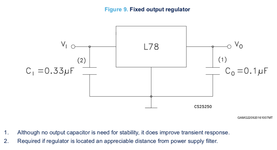
The batteries can be of different values of voltage, but this is not a problem with the L7805CV, as long as the voltage remains in the limits provides for the datasheet, for a fixed output regulator the circuit is:
![]()
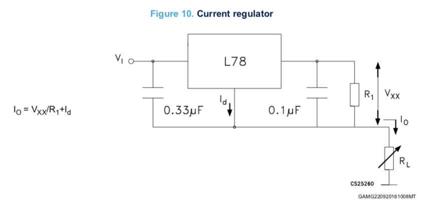
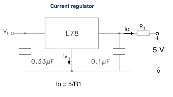
And the recommended circuit for a current regulator is:
![]()
But I'll use:
![]()
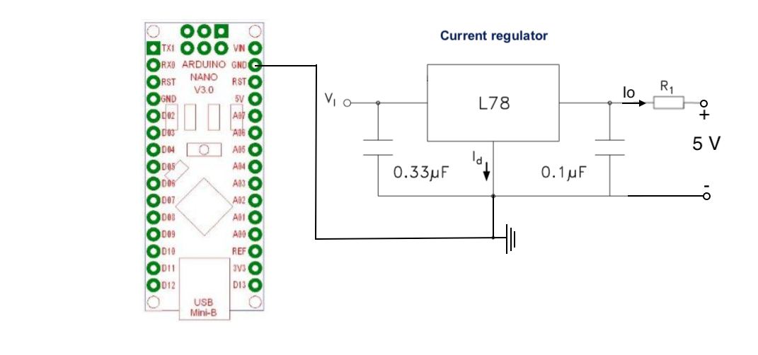
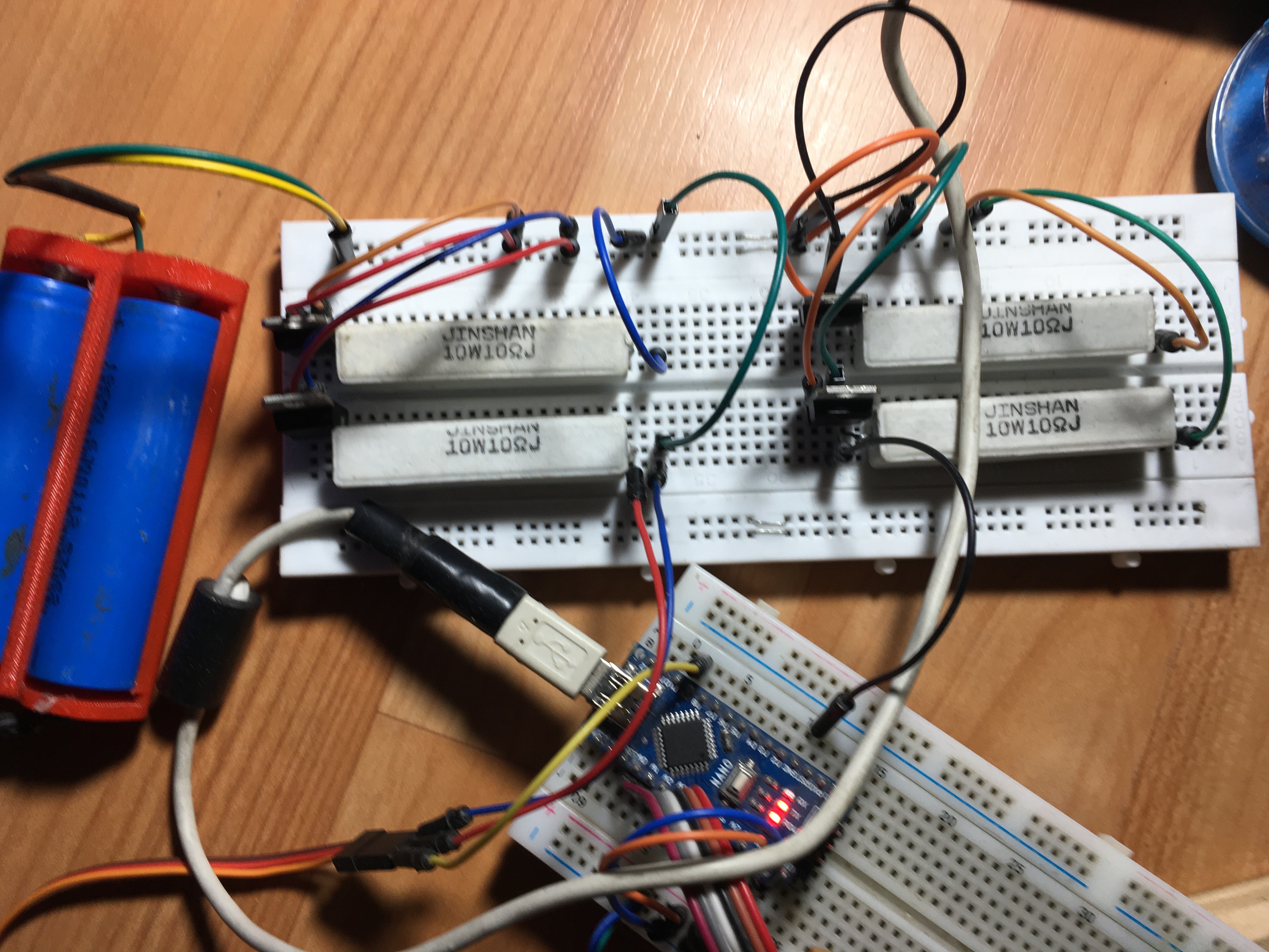
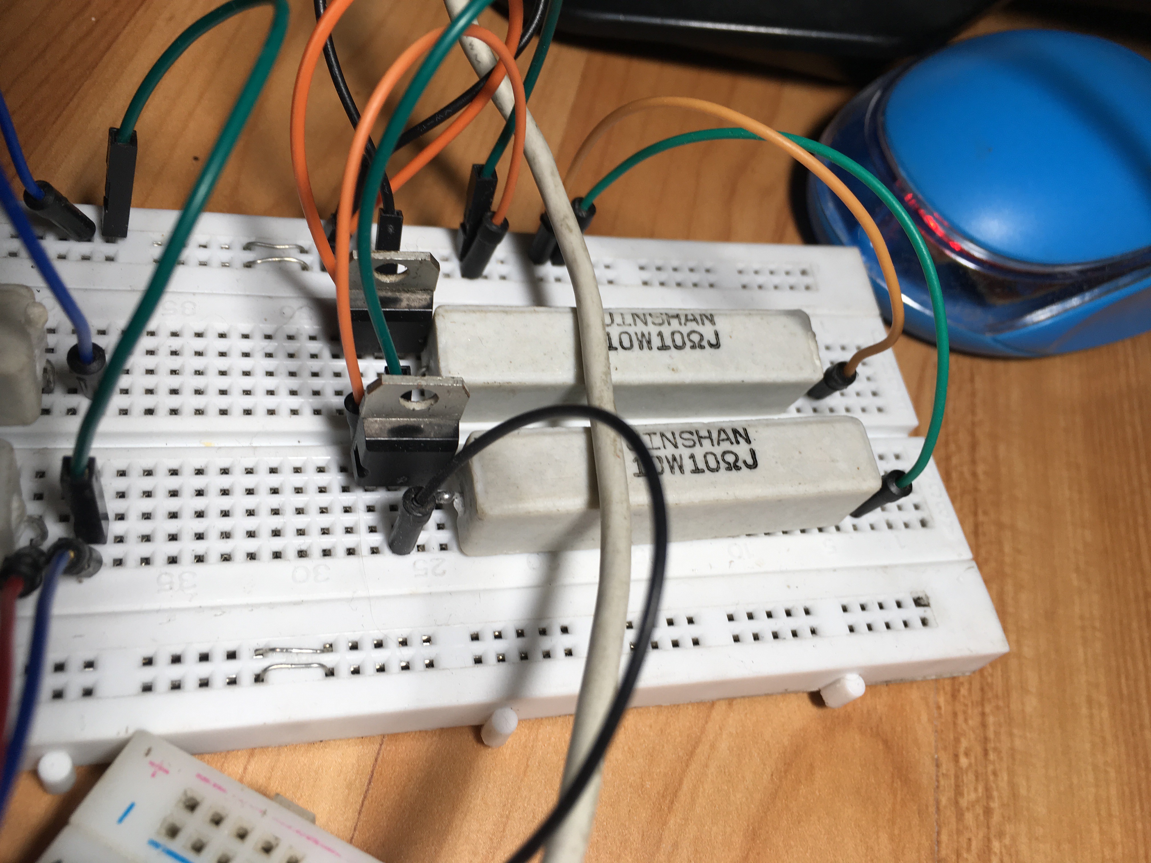
It can provide 5 v with 500 mA in a constant way (due the resistor is 10 ohms), this circuit must be a common ground with the Arduino:
![]()
To charge the batteries you can use any lipo charger like TP4056 module, and the batteries that I use are two Li-ion 3.7V recycled from an old laptop battery.
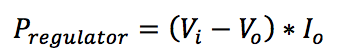
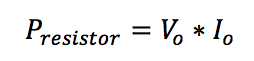
Is important consider the power dissipation in form of heat from the regulator and the maximum power supported by the resistance, to calculate if you can use these equations:
![]()
![]()
Finally here you have a picture of my circuit:
![]()
![]()
*Due that the power through the resistance are 1.5 wats is not necessary a 10 wats resistor, but is what I have at the moment.
-
Stage 6 - New equations and Vr Test
08/14/2018 at 16:37 • 0 commentsDue the equations presented for the Position and Orientation Acquisition System has some issues, I decided to figure out why it happens and try to solve it. The clues are:
- I modeled the equation from Denavit-Hartenberg parameters through MatLab, and when I use the forward kinematics functions for the model it works perfectly.
- When the equations are tested in the real system a dependence between the axes appears, nevertheless it "try" to move as expected
It can be generated by two possible mistakes:
- The modeling is wrong formulated in some part .
- The device is wrong calibrated.
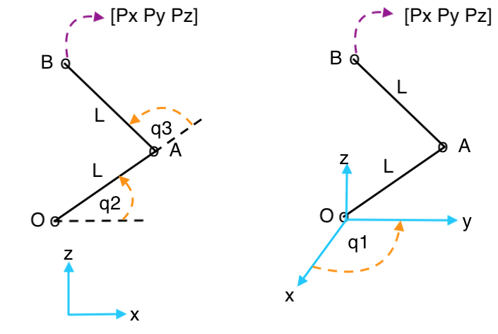
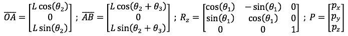
I tried to recalibrate and formulate variations of the model several times, but nothing works, so I just make another representation of the model by vector instead of Homogeneous matrix representation. The position of the end effector and its orientation are analyzed independently, the model is:
![]()
![]()
where:
![]()
[Px Py Pz] is the end effector's position. The orientation is presented as the homogeneous transform form, so:
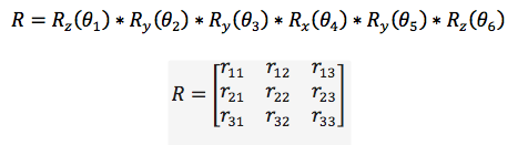
![]()
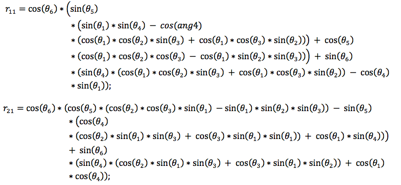
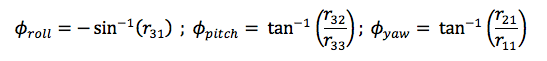
Where Rx, Ry and Rz are the canonical rotation matrix in each axis. To represent it as Euler angles (r,p,y) we need to make relations between the elements of the rotation matrix R, so:
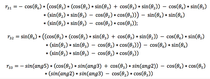
![]()
![]()
The Euler angles are:
![]()
This is tested in a virtual environment in Unity (just move a cube) as the next vídeo show:
-
Stage 5 - Wolfverine module
08/05/2018 at 03:44 • 0 commentsThis module essentially consists of a work based on wolverine haptic system (by a sort of reverse engineering with the video available on youtube ). In this stage the main measures in mm, its composition, the materials, and building. With respect to the algorithm, as it mathematical background, an outline review will be present.
The goals are the same that in other modules, cheap, easy to build and implement.
The idea is the, through a mechanical break, a person can "feel" the grasp of an object (real or virtual) with him two fingers (thumb and index), a potentiometer will be used to measure the distance between the fingers.
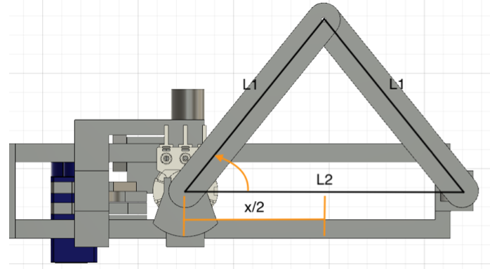
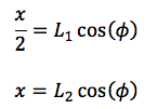
1 General design and mathematic model
The mathematical background of this module consists in a rectangle triangle formed with the half of the equilateral, so, as all length of the triangle are known, to found the distance just form the next trigonometric relation:
![]()
If we look carefully, 2*L1 is equal to L2 when the angle is zero, so:
![]()
Where x is the distance between the fingers. Now a little explanation of how the break works:
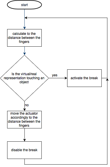
2 Coding
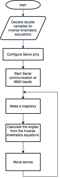
The general scheme for any application must follow the next flowchart:
![]()
3 application
The application will be present in a further Stage due to its extension, but you can see a video of how it works now.
-
Stage 4 - Delta robot
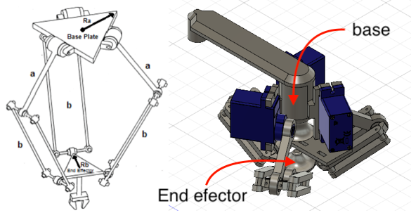
07/28/2018 at 02:45 • 0 commentsIn this stage, we'll see the mechanical, mathematics and coding aspects of a delta robot that is used as a haptic device for a finger. The main goal is that the mobile platform of this robot move a tiny half sphere to simulate the touch of some virtual environment or a feedback of a sensor of pressure (or something like that), as the other modules, the idea is that it be cheap, easy to replicate and implement in other projects jointly with position and orientation acquisition system.
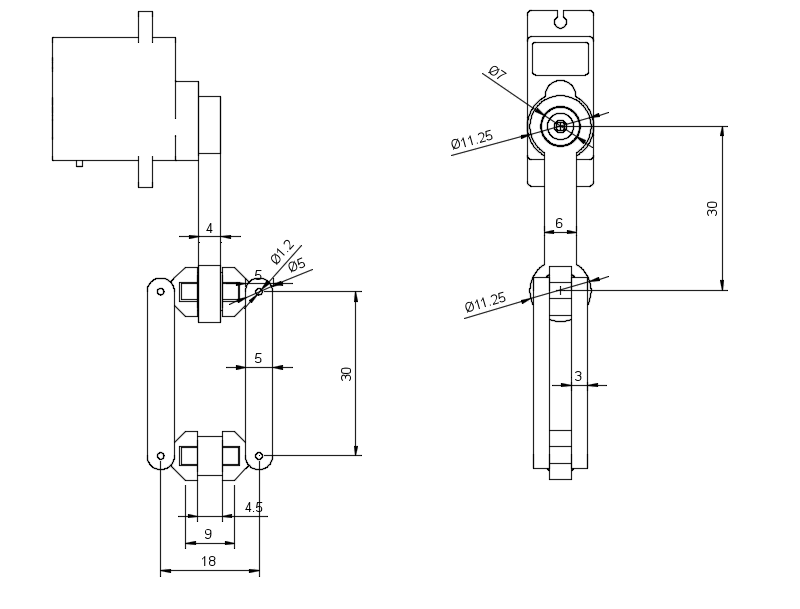
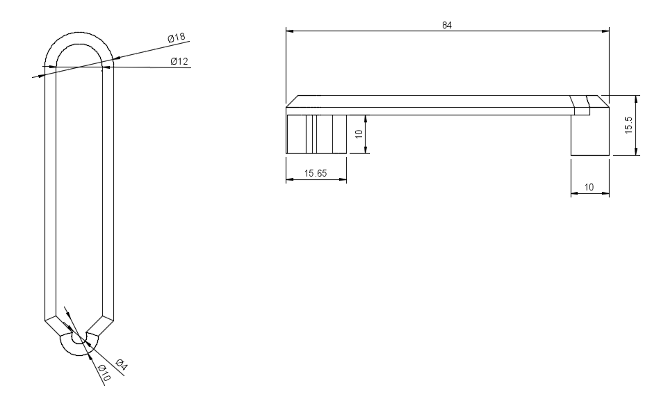
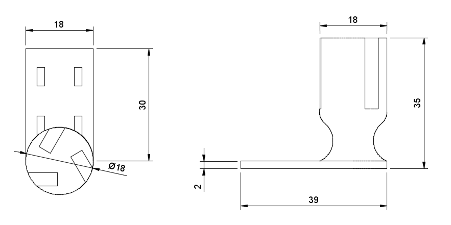
1 Mechanical design and mathematic model
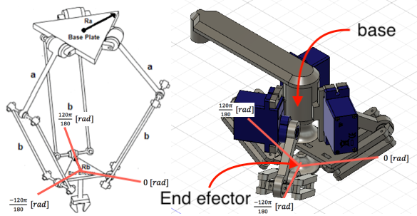
The CAD and its main measures (in mm, because metric system rules!) are:
![]()
![]()
![]()
![]()
![]()
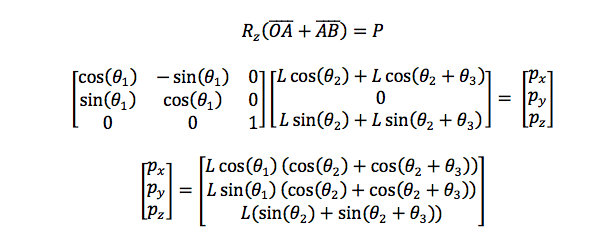
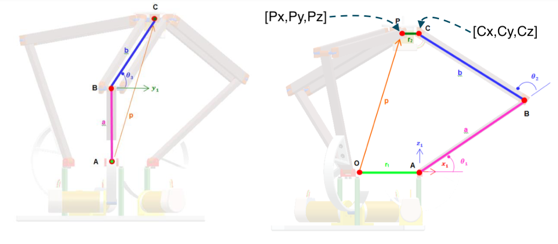
The mathematical model is based in the next image, there you can see letters (like A, O, B, P, and C) that represent points in a 3D space so, OA represents the vector that starts in point O and ends in point A, the minuscule letters represent the magnitude of this vectors (how long is). With this, we can start to make spacial relations between those vectors and, for comfort, operate them as matrixes, so:
![]()
Where "O" can be consider as the origin of the frame, while "P" is the middle point of the mobile platform, to save time (currently I'm in the middle of exams D: prey for me PREY FOR ME) only one arm will be analyzed and, through the rotation matrix in z (Rz), the other arms will be extracted immediately, so:
![]()
Where:
![]()
And corresponding to the angle of the arms, and for extension, their position, as the image bellow shows:
![]()
The other vectors are:
![]()
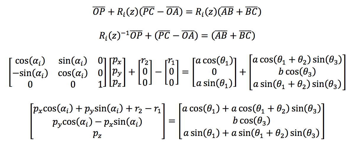
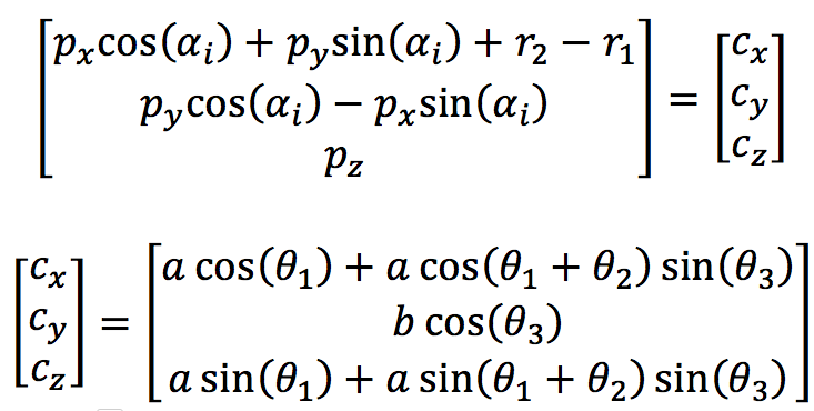
Is important to keep the goal in mind, we must find the theta angles that correspond to the angles of the arms, so, we can think in make a system of equations from the vectors that represent the structure of one arm:
![]()
If we look carefully both sides of the equation can represent the vector of the point [Cx Cy Cz], but only in the left side all variables are known, then, for simplicity, it can be represented as:
![]()
Now theta 3 of the ith arm can be obtained directly from the matrix as:
![]()
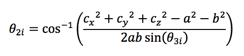
Sadly the ith angle theta1 and theta2 can't be obtained directly from the matrix, so, taking advantage of the trigonometric transformations, the square of the elements of both sides of the equation will be added, so, for theta2 of the ith arm:
![]()
From the last expression, theta2 can be easily obtained:
![]()
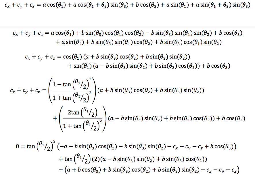
To obtain theta1 of the ith arm, the column elements of both sides of the matrix equation will be added, so:
![]()
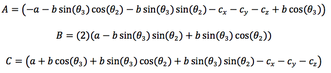
To improve the visual aspects of the last equation the next auxiliary variables will be used:
![]()
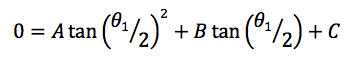
Finally, the second order trigonometric equation is obtained:
![]()
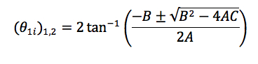
So, the solutions for theta1 of the its arm are:
![]()
The video bellow shows the Matlab validation and real test of the equations obtained:
2 coding
I've not too much to say about coding, you know, just write the equations and give it a coordinate to calculate the right angles, this is the magic of model something mathematically if your assembly is correct, the real device must respond, in this case, as the simulations show, nevertheless here you have the flowchart of the program:
![]()
3 application
The application for this module will has a special section due the extension of it.
-
Stege 3 - Test module
07/24/2018 at 00:18 • 0 commentsOn this stage, the functionality, measures, and tests being presented, really this is a very simple module so don't expect anything too fancy.
1 General design
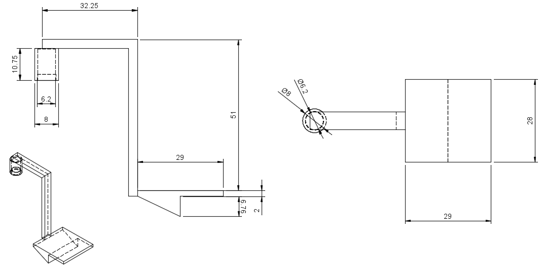
Structurally this module consists in a simple square platform with an extension in one of this sides to hold it with the position and orientation acquisition system, besides in the bottom there is a triangular form to put a button and use it in a more affordable way, the main measures in mm are:
![]()
2 Circuit
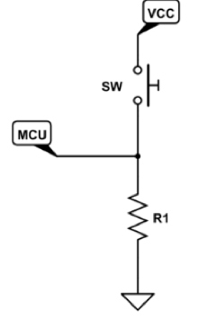
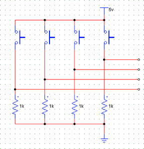
The circuit used for the electric part of this module is very simple, in essence, consist in an array of buttons with its respective resistance (of 1K ohm) to the ground, the analysis with respect to the power consumption being presented in another stage, then the circuit is:
The whole circuit is:
3 Coding
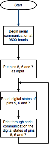
The scheme of the algorithm will serve as a base to any other project of your interest, therefore, the necessary parts of the code and its flows will be presented, the scheme is:
![]()
As you can see, the dynamics of this scheme is very simple, roughly it sensing the digital states of the pins used and realize a determinate action. The position and orientation of this modules, as the other, its given by the system presented in stage 2.
4 ApplicationFor this test, an Arduino Due being used to simulate a mouse, the main goals are:
- Test the buttons.
- See if the orientation and position acquisition system works fine with modules
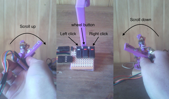
The main process of the algorithm is: take an arbitrary central position of which the distances in x, y and z-axis will be measured, this magnitude be scaling to transform it in a constant movement of the mouse in the respective axis in the screen, if this magnitude is big, the mouse's movement will be big.
The way to simulate it is through the buttons and roll angle, the next image illustrate that:
![]()
The tests show that the arm works fine, besides the buttons works perfectly (I don't need to add a 555 to control the internal erratic switching that happens when it is pushed). The mouse's movement works as planned in general terms, but it looks faster than a normal one, so it can be a little difficult to use, it can be improved with a better algorithm, the next video shows that.
Follow the same idea, other application is:
-
Stage 2 - Position and orientation acquisition system
07/22/2018 at 04:02 • 0 commentsThis system must acquire the position an orientation of its end effector or, to be practical, of the module connected in the end effector, for this purpose, a typical six degrees of freedom robot structure has chosen (like touch haptic system) whose end effector will have an extension to add and remove modules easily, these modules can be whose presented here or any other of your creation. The intention is to create something versatile and flexible and portable, so a circuit that can provide a constant power and regulate it will be present in a next stage.
1 Mechanic design and mathematic modeling
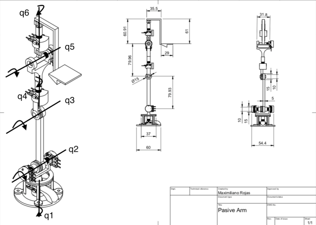
In a standard six degrees of freedom robotic arm structure, every degree is a revolute one, so potentiometers should work for angle sensing, as I guess in Touch haptic system, two three potentiometers must remain in the base and a pulley must be used to measure the wrist angle, the structure is:
 general structure. B) Structure that will be used.")
A) general structure. B) Structure that will be used.
The main measures of the structure, in millimeters (because of metric systems rules, yes, I'm a fanboy of metric system), are:
![]()
There are a q(n) axes in the last image, this represents the axis where the angles will be measured,as you can see, there are two potentiometers in q2 axis, this is for maintaining the major quantity of sensors in the base. To measure the q3 angle we can measure the angular difference between the potentiometer connected through a pulley to q3 and the potentiometer who measure the q2 angle.
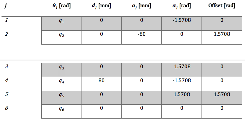
To calculate D-H parameters we must put a frame of reference in each revolute degree of freedom q(n), in this way we can do the corresponding relations be to obtain the homogenous matrix of each frame and then, obtain the forward kinematics equations, for this I used MatLab with its robotics toolbox, then the parameters are:
![]()
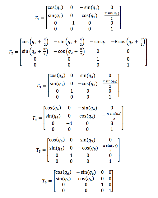
Now we just replace this values in the standard homogenous matrix presented in State of the art stage, where T(n) represents the matrix of q(n) frame:
![]()
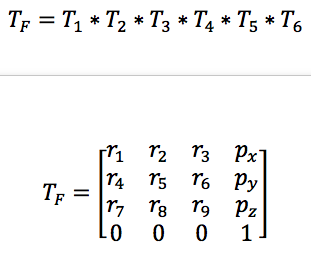
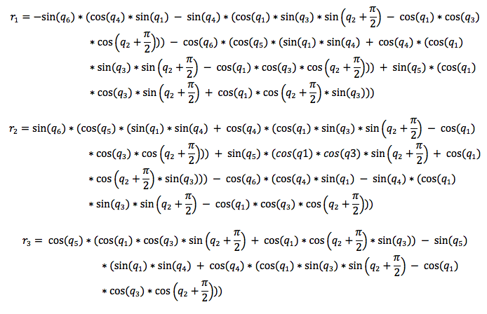
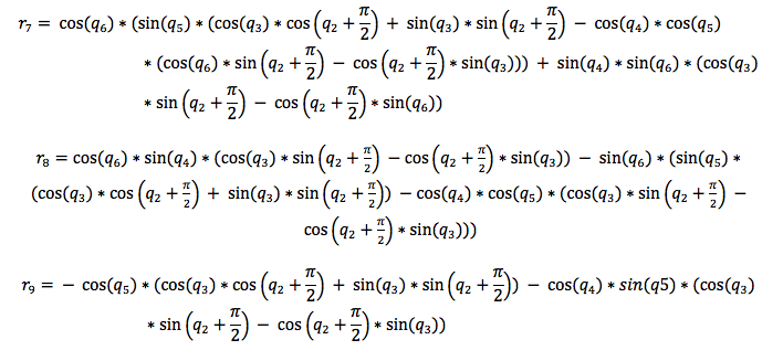
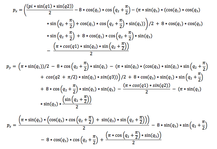
To obtain the position and orientation of the end effector with respect to the base we must multiply all this matrix, then, the equations obtained can be freely implemented in an embedded system, microcontroller, pc, or any other programmable system that support this processing. Tf represents the final matrix:
![]()
![]()
![]()
![]()
![]()
* Don't worry, I'll upload a word file with these equations.
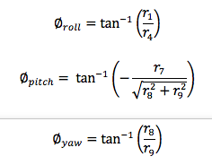
The position vector can be extracted directly from the Tf matrix, but to obtain the orientation in terms of Roll, Pitch, and Yaw angles we must establish some relations between the components of the rotation matrix, then:
![]()
2 Coding
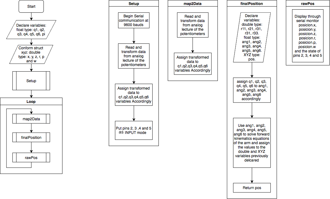
The scheme of the algorithm will serve as a base for any application that you build, for this reason, the necessary parts of the algorithm being deepened and explained, so :
![]()
You can appreciate that the flow of the coding is simple, first, you declare the variables that serve to save the respective angles of q(n) and to display the information of interest (like [x y z ] position and [r p y] angles), later, through the "setup" sub-process the initial configurations are established.
Inside the sub-routines, in the iteration part, it can be appreciated a very logic structure, first, a lecture of the voltage of the potentiometers is done for, then, transform it to a useful range in radians (this process is done by "map2Data" sub-routine), next, an auxiliary variables are declared to calculate de forward kinematics equations, in this way it can return the components of the Tf matrix (this process is done by "finalPosition" sub-routine), last, the values obtained are displayed through serial monitor (this process is done by "rawPos" sub-routine).
If the code is structured in functions, is proper to guess that the implementation in other projects will be easy and fast, after all this is one of the main goals.
3 Test
movements, looks erratics, so at the end of this project, I will add a first IIR filter that corrects that.
-
Stage 1 - State of the Art
07/20/2018 at 03:39 • 0 commentsFor a better comprehension of the design and development aspects, I'll present a series of haptic systems that serve as inspiration for this work, besides a little of mathematical and electronics background will be mentioned for a better understanding. It's mandatory to present the names of the programs that I used or will use for this project as the code implemented in the microcontroller that can be used as examples for who want to deepen on this topics, or inclusive in the same project, in a more guided way, now, without any further ado:
1 Mathematical background
In this sections, the Denavit-Hartenberg parameters and the homogeneous matrix will be explained, especially in what extraction of data refers.
1.1 Denavit-Hartenberg parameters
The Denavit-Hartenberg parameters are very useful to describe, in a systematical way, the kinematic structure of a serial robot, the method consists in finding a series of relations between two frames (or vectorial spaces to be more precise) in such a way that, through a special kind of matrix, appears a linear transformation that allows us to convert vectors of one frame to another of reference. This makes easier to found, for example, the position and orientation of the end effector of some robotic arm taking the base of this (or any other point of interest) as our frame of reference. The parameters are:
 *Extracted from Peter Corke-Robotics, Vision and Control. Fundamental Algorithms In MATLAB book, I really recommend this book in case if you want to deepen.
1.2 homogeneous matrix
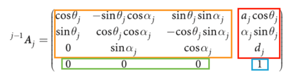
This matrix is a way to represent a linear transformation between two frames in such a way that the orientation and position of a spot are defined in one frame of reference (j) with respect to another (j-1), its structure is defined through the Denavit-Gartenberg parameters and is:
![]()
In a general way, with Denavit-Hartenberg parameters, is:
![]()
Where the sub-matrix are:
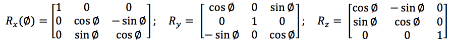
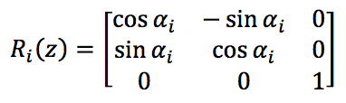
- Rotation matrix: This sub-matrix associate the rotation of one frame and returns its equivalent with respect another frame (like the orientation of the end effector of a robotic arm with respect to the base of this robot) and you can extract the roll, pitch and yaw angles from the relations of its components. It has three canonical forms that correspond to the rotation in the three main axes (x, y, z), those are:
![]()
- Translation matrix: The components of this matrix represent the x, y, and z of a point in a 3D space after to apply the linear transformation, there is no any standard or canonical form because its depend on the structure of the robot and the joint considered.
- Perspective matrix: Through this sub-matrix, you can transform the perspective of a frame through projections managed for its components, no perspective modifications correspond to [ 0 0 0 ] vector.
- Scaling matrix: Through this sub-matrix, you can scale the dimensions of the frames of interest, the normal dimensions are given by the vector [ 1 ].
2 Digital filters
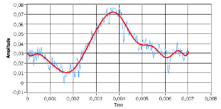
In case that the sensor used returns a series of samples with no desires high-frequency components, you can design a low-pass filter that "softens" the curve of the signal that is processing in such a way that no exist any abrupt change in the systems that used this data as input, for example a filtered signal is:
![]()
red - filtered signal blue - normal signal
To solve this problem we may consider using analog filters (like an RC circuit), but this present two big problems, first, electronics components has error margins in their values not only by its production (like the tolerance in resistors) but for external or physical problems too (like overheating), and second, if the order of the filter is too high it can be very expensive to build. So, for solve this we will use IIR filters.
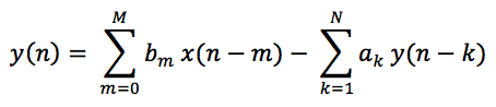
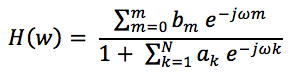
IIR filters (infinite impulse response) are those that the output of a processed signal depends on a determinate number of samples scaling by coefficients, where is there the challenge of the design, found the proper coefficients for the desired response, the mathematical form of this is:
![]()
As you can see, the output signal y(n) depends on both inputs (actual an already used) and outputs already processed, then, depending on the order N of the filter, the coefficients to determine are:
- M + 1 coefficients "bm" of the input.
- N coefficients "ak" of the output already processed.
Once we have the coefficients, the frequency response can be obtained by:
![]()
Nevertheless, thanks to the algorithms implemented in Matlab, the digital aspects can be analyzed and then, through a faster analog filter design, generate the digital filter, we can convert analog filters into digital ones with only a command, but its imperative to consider that the relations between the sampling frequency and the digital equivalent of the analog frequency don't break the "sampling theorem".
*sampling theorem consists in that our sampling frequency must be bigger than the double of the highest frequency contained in our analog signal.
It may happen that our sampling frequency change due to externals perturbations, for example, for overheating or algorithm that change its time of operation, to fix that we can implement a first-order IIR filter because exist a systematic way to have the coefficients, and this method can be implemented in a microcontroller with a timer, but I don't think that this will be necessary, however I mention it in case of this be of some utility for someone.
3 Haptics devices
In this section will be presented and analyzed briefly some haptics devices that serve as inspiration for this work with a special interest in those characteristics that can be replied through some sort of visual inverse engineering by means of images and videos available in the developers official pages.
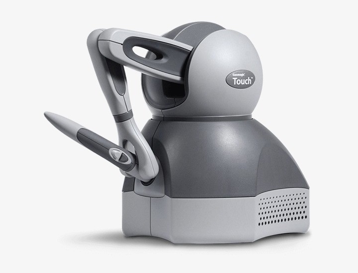
3.1 Touch
This haptics device was development by 3D-SYSTEMS company and its principal features are to be compact and portable, it can measure 6 degrees of freedom, three for position and three for orientation, besides it has a three degree of freedom force feedback (for the position). Its end effector can be removed and replace with another provided by the company, like a pen with two buttons.
![]()
This structure is quite interesting because of its look like a standard six degree of freedom robotic arm, surely had three degrees of freedom concentrate in the base and through a pulley, it can measure the elbow angle.
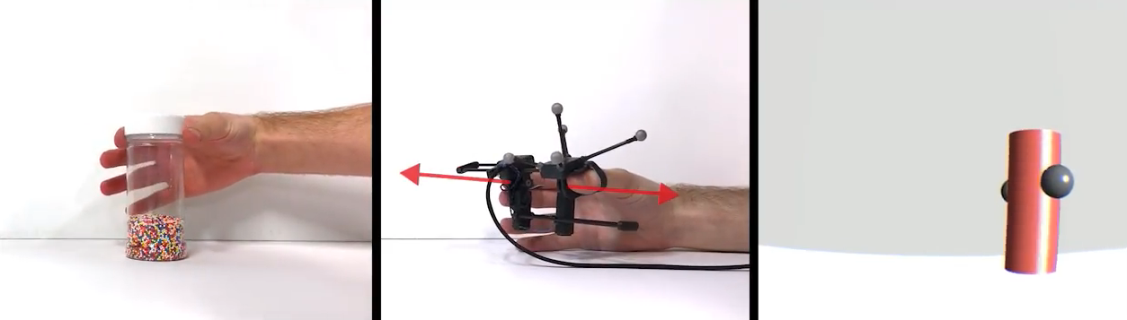
3.2 Gravity
This haptic interface developed by Stanford University to simulate weight and grip of a virtual object. It has four degrees of freedom feedback, three for inertia sensation and one for grip. In this case, the way that this device holds a determinate position is interesting, the design of the break looks tiny but efficient, I think that this can be replied in a more cheaper an simpler way, but probably bigger.
![]()
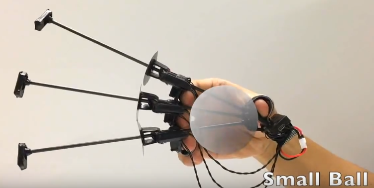
3.3 Wolverine
This is another haptic device developed by Stanford University specially designed to grasp virtual objects, is like the tiny version of Wolverine, but for each finger! It can measure the orientation of the hand and position of each finger, those little parts with the circle are brake so if I can reduce the volume of the replies of Wolverine's brake, I will try to reply this one.
![]()
4 Programs
These are the programs that I use or will use for the design, test and validate all:
- Arduino - coding
- MatLab - coding and simulation
- Fusion 360 - CAD desing
- PSIM - Circuit design
- Unity - VR applications
5 Bibliography
If you want to go deepen on this topics I strongly recommend these list of books:
- Fundamentals of electronics circuits - Alexander Sadiku (basic circuit theory).
- Introducción al procesamiento digital de señales - Juan Vignolo (digital signal processing, sorry it is in Spanish, but is a very good book) .
- Vision and Control. Fundamental Algorithms In MATLAB - Peter Corke.
- Robot Analysis: the mechanics of serial and parallel manipulators - Lung-Wen Tsai.
- Fundamentals of Robotic Mechanical Systems: Theory, methods and Algorithms - Jorge Angeles (very heavy in its mathematics).
[2018]Multipurpose modular haptic control
This project has an intention to develop a haptic device that can control almost everything, it must be cheap, easy to build and implement.


 general structure. B) Structure that will be used.")

 *Extracted from Peter Corke-Robotics, Vision and Control. Fundamental Algorithms In MATLAB book, I really recommend this book in case if you want to deepen.