-
improving filtering. will include optical offset. still trying for better filtering
11/11/2018 at 00:29 • 0 commentsthe 128x128 subsample method is noisy. i'm trying to resolve this by fixing possible issues using simulation.
i'm currently simulating upsample in javascript code. ill post a link when web version is uploaded and article is up for the non float upsample method used. i thought it would have been uploaded a week or so ago but it will be out this next week sometime. i hope to have it capable of 32x32 (the simulation) and eventually 128x128. this simulation code will help me fix noise issues at 128x128 and possibly greater upsample resolutions.
i have already included optical correction which compensates for individual sensor variation of angle. this effects and improves the pixel color accuracy. i included compensation on a hunch, and with trial and error it proved to be the correct thing to do. it slightly averages pixels together about 1/16 depending on specific settings in code. this is before subsampling is used.
there is an other effect that i am going to implement that will make image upsampling have less shadowing and it is pixel offset calculation. depending on position of sub sampled pixel there should be a set amount of offset to its brightness value compared to its neighbors.
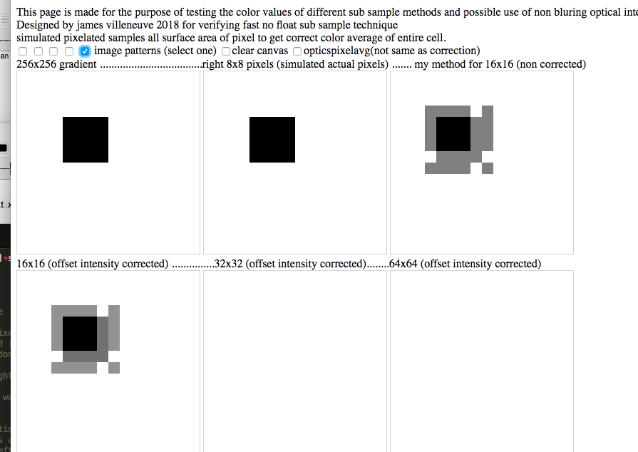
i would have posted more results sooner, but i ran into this optical error, it can be viewed in both upsampled views and shows with a darker and lighter shadow in both 16x16 and 16x16 corrected.
i have spend a little bit of time trying to see if i could make this better. granted in real life such a sharp contrast in backgrounds would most likely not be possible, but i spent time to see if there was something that could be easily done to make it look better.
![]()
after bit of trial and error i found out that even with other upsample methods this specific sharp contrast and small size of image had issues with other upscale methods. so it is not just my method that has this issue, it still bugs me, but not as much as it did. part of the issue is no shadow information in image. this would not be an image in real life.
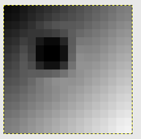
here below is how it is output thru gimps upsampling algorithms from 8x8 grid to 16x16 grid, image was cut and pasted from screen snap shot of image scaled to screen 1600%
![]()
I will see how this algorithm works to see if improvements can be made in my subsample method.
-
ili9341 320x240 at >10fps(20fps interlaced) 32x32 interpolated blocks) using amg8833 sensor
11/07/2018 at 02:22 • 0 commentsbeta release of ili9341 display working at an average of 10fps (20fps but interlaced). need to finish up feature changes and buffer size adjustments for mlx90460 sensor, then get 64x64 mode working for ili9341 display.
including new features on 32x32 mode such as AdvancedColorVisualSeperation. setting this with a number greater that 0 enables it. whatever number above what you set to is the color range intensity that is amplified, so unlike narrowing temp range which also brings more noise, this just shows more details around objects. im still working on methods that handle saturation, currently i'm just clipping it at max intensity false color value
and optimize 3 setting that reduces display writes by half, and some other minor tweaks.
also starting to put in code that allows sensor buffer size to change. this is important for adding mlx90460 sensor to be used in code in future.
to turn on and off AdvancedColorVisualSeperation set it to true or false. it can saturate images.
-
simple thing that can speed up any ili9341 display in my case additional 20%
11/06/2018 at 00:01 • 0 commentsSince i have been getting the ili9341 display ready for fast 32x32 (and 64x64, 128x128) subsampling of amg8833 sensor the ili9341 display has 4 times as many pixels as the st7735 display i have working at fast speeds. to increase performance i am doing tricks that cut down display writes to about half, and the rest is thru driver optimizations.
I have found out that the driver for set window always sends 4 byte commands for x, and 4 byte commands for y no matter what the display position is, yet most of the time only one or the other is needed.
here is the setAddrWindow command driver as it is in ili9341 driver :
void Adafruit_ILI9341::setAddrWindow(uint16_t x, uint16_t y, uint16_t w, uint16_t h) {
uint32_t xa = ((uint32_t)x << 16) | (x+w-1);
uint32_t ya = ((uint32_t)y << 16) | (y+h-1);
writeCommand(ILI9341_CASET); // Column addr set
SPI_WRITE32(xa);
writeCommand(ILI9341_PASET); // Row addr set
SPI_WRITE32(ya);
writeCommand(ILI9341_RAMWR); // write to RAM
}here is my optimization. it reduces command overhead by 33%. still you will need to send either x, or y and at least set ram buffer command on each screen location update. my goal is to not use screen location updates but they are needed at least for every square block write to display (64 times) or when only writing half the display one time per line call so we can skip a line, so 64x15 (64 blocks. a block on this display is 30x32 pixels) or 960 times per frame. the time savings is significant enough to raise frame rates about 20% in itself when doing half fill mode as location window changes every other line for fills within a fill square of multiple colors.
keep in mind the caching of values and comparing. if no change we don't write both x and y we only update one of them.
long xaCache ; //two ram values that use 4 bytes each are needed to make this work.
long yaCache; //place values at top of page where the code is, in my case it is adafruit_ili9341.cpp
void Adafruit_ILI9341::setAddrWindow(uint16_t x, uint16_t y, uint16_t w, uint16_t h) {
uint32_t xa = ((uint32_t)x << 16) | (x+w-1);
uint32_t ya = ((uint32_t)y << 16) | (y+h-1);
if (xaCache != xa){
writeCommand(ILI9341_CASET); // Column addr set
SPI_WRITE32(xa);xaCache = xa;
}
if (yaCache != ya){
writeCommand(ILI9341_PASET); // Row addr set
SPI_WRITE32(ya);yaCache = ya;
}
writeCommand(ILI9341_RAMWR); // write to RAM
} -
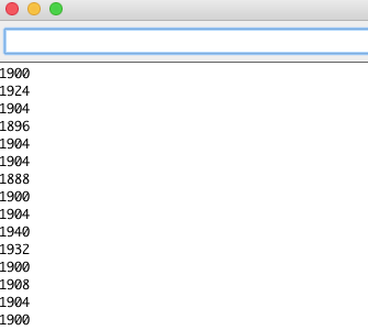
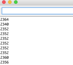
reduced block write time from 2300us to 1900 (this is for 32*30 pixels area)
10/18/2018 at 05:09 • 0 commentsthis is for ili9341 display. it has 4x as many pixels to write. if we write every other pixel line we get similar visual with 2x performance. since we can only go up to 128x128 (this is scaled to 2x2 pixels per sample on this display) sub sampled (only 64x64 with good results so far) this seems acceptable. 128x128 is being worked on and will be updated within 2 weeks. i've got an other article blog coming out on how to do super sub sampling without floats.
more pixel writes in a row make faster pixel writes because every time you change x or y position requires command overhead. just by switching direction that lines are made for every other line write it speeds up 8x8 block size (30x32 pixels) to 1900us, from 2350us. instead of writing 30 pixels and having 16 write new position commands overhead, we have write 32 pixels with 15 new positions command overhead. only difference is we write top to bottom, rather than left to right. we write 64 of these blocks
![]()
this equals 8.22 fps *2 (keep in mind buffering blocks reduces writes 2x -5x!, so average frame rate is 16.44fps)
-
beta version of ili9341 working 10-15fps in 16x16 mode download link
10/18/2018 at 04:42 • 0 commentsthis version has 16x16 working quickly on ili9341. 32x32 mode is about to be uploaded. current 16x16 drivers are only completed enough to allow for 16x16. when 32x32 mode is ready 16x16 will be re uploaded with latest drivers. 64x64 sub sampling should be working by end of week. it already works for st77xx displays, the ili9341 has 4 times as many pixels and also requires different display drivers. the above download link should work out of box for ili9341, and amd8833 sensor
-
you can write half as much data to ili9341 display and have it look great!
10/17/2018 at 21:40 • 0 commentsthe screen resolution of the ili9341 is 4x what the st77xx display i also support is. i have done optimizations that speed up ili9341 spi performance
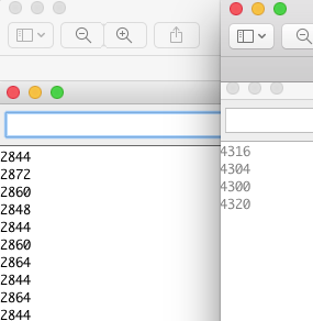
here is how long it takes to write a solid 30x32 block (creates a near square pixel on screen in 8x8 mode, on 320x240 display)
default driver is on right side for timing in microseconds, spi optimizations is on the left side (we do calculations or data manipulation while spi is writing, instead of stopping and waiting for spi to complete.
![]()
but it gets even better.
![]()
if you only write every other line (you send a lot of data, and write every other line, you get better performance. not as huge as before, but it makes frames per second higher. up to 64 of these pixel blocks are written every second (buffered modes reduce this about 50%)
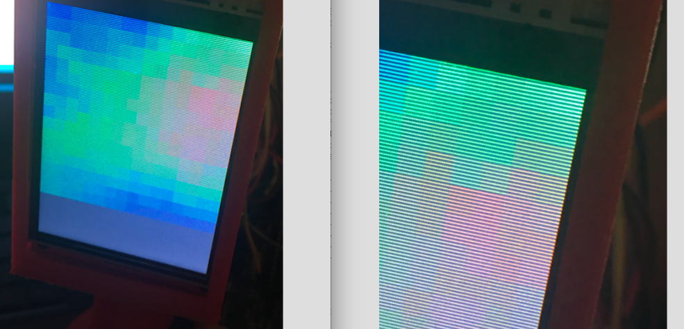
and here is the image results of just writing every other line on screen
![]()
you really can only tell if your eyes are within 6 inches of display. it might be touch screen plastic over the display or the display itself, it diffuses the light, so the gap between lines is minimal.
here is some data without processing overhead (300us) to show best frame rates possible with defaults and so far.
default driver: 4300us per block= 4300x64=275200 or 1000000=3.6 fps best case
spi optimized :2850us per block= 2850x64=182400 or 1000000/182400=5.48 fps * 2 (just over 10fps buffered)
this mode: spi optimized :2360us per block= 2360x64=151040 or 1000000/151040=6.62 fps * 2
remember not every pixel updates or changes at once. using buffers 2x-5x frame rates.
default driver does have buffering but only on arm cortex.
i think i can also make every other line method better by making pixels area larger. the more in line writes at a time the fewer set pixel overhead commands are used. to get every other line i had to increase command overhead for each line start.
video below is in 16x16 sub sample mode for the ili9341 display. i still need to modify drivers to do more resolution (little overhead) most of overhead is display writes. the st77xx display can do 64x64 subsample well.
-
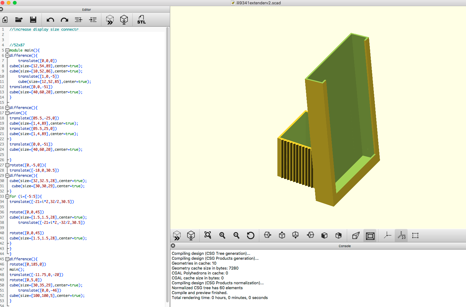
new ili9341 extender. tilts display upwards for easier viewing
10/16/2018 at 20:21 • 0 commentsili9341 display i'm currently making display drivers for, needs a better viewing angle. in testing the display angle is hard to see, so i tilted it up a little bit. it still slides into the thermal cam housing design here:
https://www.thingiverse.com/thing:3050327
here is a digital image of ili extender
![]()
-
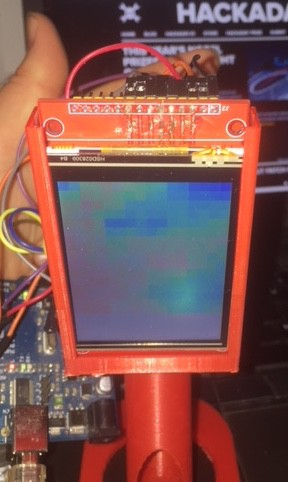
ili9341 starting to work in thermal cam! lots of speed up work to do. it is also a touchscreen. Creating driver for this display that will optimize it as well.
10/13/2018 at 04:55 • 0 commentsili9341 working on Arduino. led backlight power lighting is in 3v pin, and lcd power 5v icsp header along with gnd miso and mosi pins, enough power pins are left for powering amg8833 or mlx90460 sensor. there is other pin i/o to spare for touch and other devices. larger display might require more than a dry cell 9v can deliver. switching to alkaline, or running 2 9v in parallel. will keep posted on batteries used. for now it is back to using usb, while testing and rewriting drivers
![]()
ili9341 working on Arduino.
![]()
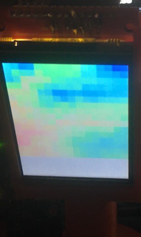
using 16x16 resolution for testing image without camera flash. on the st77xx display i have it working good to 64x64, while 128x128 works but has artifacts still.
screen shows dim from camera flash, testing it in 16x16 mode. drivers not optimized. adafruit has made some changes to the workings of the SPITFT of the drivers, and it means that the ili9341 drivers work a little different. i am not able to combine libraries so i have added a new sketch that defines what spi mode (internal library or one i include and a lcd_mode sketch that i can just drop in files for and switch which drivers work or not. i use
// #if lcd_mode ==0
or //#if lcd mode == 0 at top of page code for it to run or not run .
currently running at interpolateMode of 1, or 16x16, going to test out InterpolateMode of 2 and up later on, these are 32x32, and 64x64 and 128x128. this display is 240x320. it also is a touch screen. i might get the touch screen working as well on this display. my goal is to support the ili9341 display and the st7735 display from adafruit. other displays should work with some troubleshooting. only accelerated mode will work for these two displays. ( 10fps or 20fps interlaced mode )
i have not made optimized drivers yet for the ili9341. it runs currently at an average of 8fps, but it also only updates the pixels that change and prioritizes the ones that change the most in color value. if i place my hand over sensor and take hand away and all pixels change it slows down quite a bit.
-
more ili9341 driver issues. reset was not called even though it was defined in code
10/12/2018 at 05:55 • 0 commentsduring continued testing i had other issues where display would intermittently fail after using it for a while. i checked and replaced wires, even soldered over connectors on Arduino board (they were loose anyways), finally i tried directly wiring cs, and reset. if reset was gnd it always worked. cs didn't act differently.
the code that init display for adafruit (granted this is not an adafruit display)
while using adafruits graphics tests found this issue with reset pin not even being used in code! :
Adafruit_ILI9341 tft = Adafruit_ILI9341(TFT_CS, TFT_DC);
changed it to this
Adafruit_ILI9341 tft = Adafruit_ILI9341(TFT_CS, TFT_DC,TFT_RST);
second set of problems solved. i'll check another display when it arrives saturday.
i switched inputs to this to match pin out in thermal cam sketch.
#define TFT_DC 8
#define TFT_CS 10
#define TFT_RST 9 -
ili 9341 lcd works at 5v now. but i'm not 100% sure why. to be continued. ordered 1 more
10/12/2018 at 02:45 • 0 commentshere is the display working at 5v, i'm not sure why it now works. i gave up on the resistor divider and re-soldered the connections i cut yesterday. soldering was a pain until i lifted up the lcd, and pulled up the flex, which was glued to pcb. i checked resistance of small wires i added and wire across the cut traces. although thin adds less than a 0.5ohm resistance. i checked the resistance in between between the pads and it was still high, continuity was zero .i checked resistance between gnd and wire trace assuming maybe the flux had created a resistor circuit. nope. so far the only thing that makes sense is folding back the flex cable from board. i checked glue as well, it does not conduct. i bought another display and will do two things when i get it, i will bed the flex board to release it from pcb, and if that does not work i will clean solder tip and heat up pcb to see if it breaks down to form a resistive area. then lastly i will apply flux. it is a mystery to me. ill post a how to video when i figure out why it did not work, and why it does now. i know i had wiring correctly because it did work with led used to lower voltage to 3v logic levels. when i hooked up display after fixing it from the cut traces and pulled back lcd flex, i tried testing pins individually to see if any would work at 5v ttl of Arduino. one by one they all worked, i thought weird, so i wired it without breadboard. it still worked. thought maybe 5v was plugged into 3v. nope it was to 5v.
spi write up to 64 colors at a time on Arduino!
amg8833 equivilent sensor thermal cam is a perfect example of how to write faster with spi lcd displays. 128x128 sample fast on Arduino.