Enrico
-
LED current estimation
08/23/2018 at 19:52 • 0 commentsSo far so good? Maybe! But how can you practically measure the current in the LED to demonstrate the ripple reduction?
I don't have a current probe for my scope and neither I can afford it. Secondly, measuring in a conventional way required a sense resistor, which would alter the results, and I should manipulate too much the already delicate measurements to compensate this effect and get the correct result.
KISS my LED
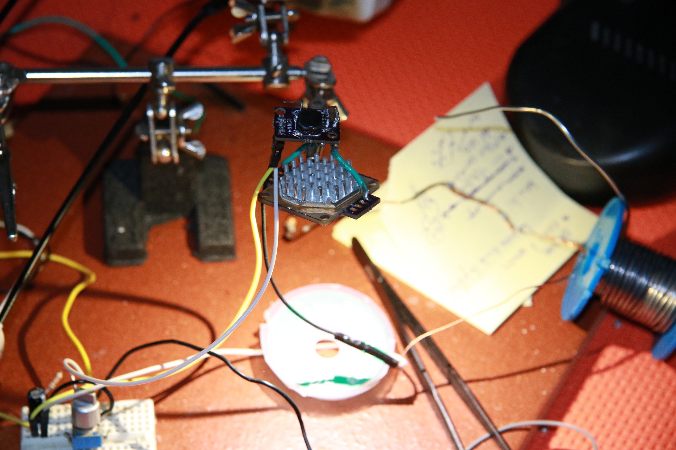
I opted for Keeping It Super Simple, you Stupid (this acronym is always different each time a read it). Here the setup, which I was staring at with sun-glasses, hopeless, trying to find a solution.
![]()
Then I realized that I had an OPT101 somewhere. I still can measure the light. But this is a somehow slow sensor. From the previous log, with my setup with a single LuxeonRebel LED, I had an operating frequency somewhere 300 kHz. Different supply and analog dimming will affect this, since it does not have any oscillation: is just the speed of the inductor to reach the thresholds!
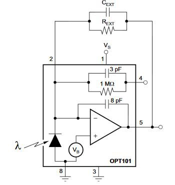
The OPT101 was used with external programmed gain:![]()
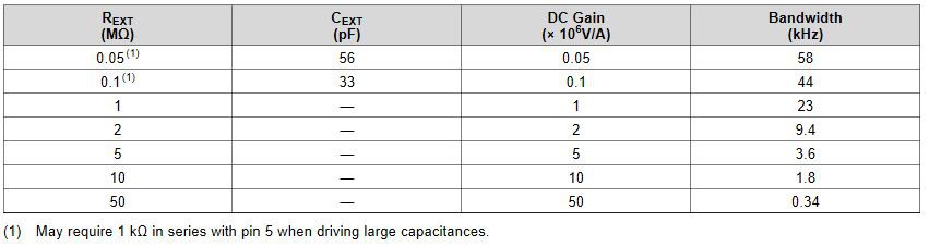
With a useful table shown here:
![]() Since I don't have any capacitor with me and 1M of gain bring a 23 kHz of bandwidth, a gain 500k could set the game of a bandwidth between 44 kHz and 23 kHz, without making stability issues. Therefore the only output component was a 500 kΩ resistor and the crude schematic look like this:
Since I don't have any capacitor with me and 1M of gain bring a 23 kHz of bandwidth, a gain 500k could set the game of a bandwidth between 44 kHz and 23 kHz, without making stability issues. Therefore the only output component was a 500 kΩ resistor and the crude schematic look like this: ![]() Here I don't care about the quantitative ripple reduction in absolute way, but more in a relative manner with respect to the solution with no ripple attenuation.
Here I don't care about the quantitative ripple reduction in absolute way, but more in a relative manner with respect to the solution with no ripple attenuation.
One last thing was to be sure that the LED could provide sensible light variation w.r.t. current variation. In my case, the operating point of the LED was somewhere near 400mA. The LED was a LXW8-PW40, with the following characteristics:![]() Still pretty linear I would say.
Still pretty linear I would say.Finally some measurements
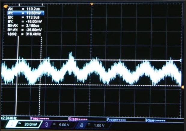
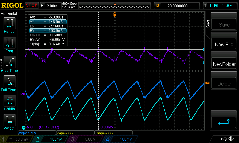
The results are showing an output from the photosensor of 35 mVp-p which is amplified by 500k times.![]()
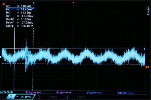
This is my reference point. Here with 300 Ω of sense resistor, reference voltage of 116 mV, results in a Iset = 386 mA. If the regulator provides +/-15% of ripple current, then 35 mVp-p will corresponds to the 32% of ripple measured in the previous log, where in current is 150 mAp-p. Applying 2.2 uF reduces this to 25 mVp-p.
![]()
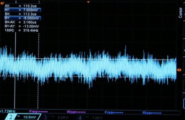
With 6.6 uF this reduces down to a value between 11 mVp-p and 13 mVp-p.
![]()
Now I have a comparison value: mathematically speaking, with 6.6 uF the ripple shall be 27 mAp-p. From the original 150 mAp-p this is 5.5 times lower. Here, 11 mVp-p of ripple corresponds to a reduction of 3.2 times from the original 35 mVp-p of the first reference acquisition.
I would say that considering the non-linearities of the flux/current characteristics of the LED, parasitics of capacitors, their tolerances, imperfections in the LED dynamic resistance and scope acquisitions far from perfect, this is quite a good result.
I would say that what was theorized in the previous log seems correct: a ripple of +/-2.5% can be achieved with a ceramic of 7.2 uF. -
LED current ripple reduction/optimization
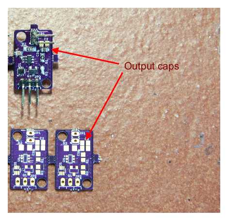
08/21/2018 at 22:08 • 0 commentsThe board carry a space for 2 output capacitors. This is done to leave space to put as many caps as possible, to experiment with EMC problem solving and accurate lumen output, where needed.
![]()
In the first assembly I put an output cap of 1uF to filter out some mid-frequency disturbance and reduce a bit the output ripple. An additional 100nF may be good as well.
Initial measurements
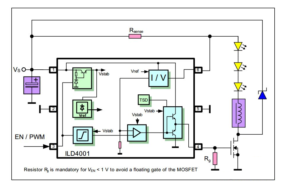
The controller is an Infineon ILD4001, and states a ripple of +/-15% in the current. With a setup at an Iset = 386 mA, I have measured the ripple, according to a sense resistor of 300 Ω. The upper current peak is 493 mA and the lower of 343 mA, with a delta of 32%.
Here how appears the current measurement the current ripple, measured across the sense resistor, in purple:
![]()
This is the overall current, which according to the following schematic, is the one flowing through Rsense:![]()
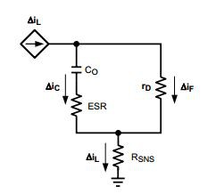
To filter out the ripple, is needed to "steer" the AC component out of the LEDs, which translates in putting a parallel capacitor across them. If the LED has a given dynamic resistance according to its bias point and the capacitors a certain ESR, the (small signal) schematic looks like this:
![]()
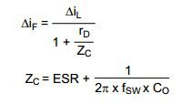
From which the current divider created let me find the ΔIf, and subsequently, from the equivalent capacitor impedance, finding an equation which provides the output ripple in function of the capacitor's impedance:
![]()
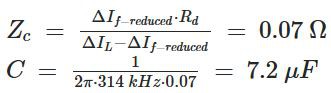
If the ΔIf reduced is, for example, from +/-15% of the initial to +/-2.5%, from the above formula:
![]()
Where Rd = 0.35Ω and the ΔIf−reduced in this use case is +/-25 mA. So, with an original 30% of ripple (+/-15%), to go down to 5% I needed at least 7.2uF.
Two low cost MLCC 0805 4.7 uF, 50V capacitors in the two available slots will do the job in all the LED configurations. Again, I did not put them (for now is the standard BOM) since it may never be an issue. But the user has the freedom to tweak it and here I just gave some suggestions.
Glighter-A, a tiny 40W LED Driver
Cheap and small, is another failsafe, analog controllable, 40W hysteretic buck LED driver, in a pill form factor.
 Since I don't have any capacitor with me and 1M of gain bring a 23 kHz of bandwidth, a gain 500k could set the game of a bandwidth between 44 kHz and 23 kHz, without making stability issues. Therefore the only output component was a 500 k
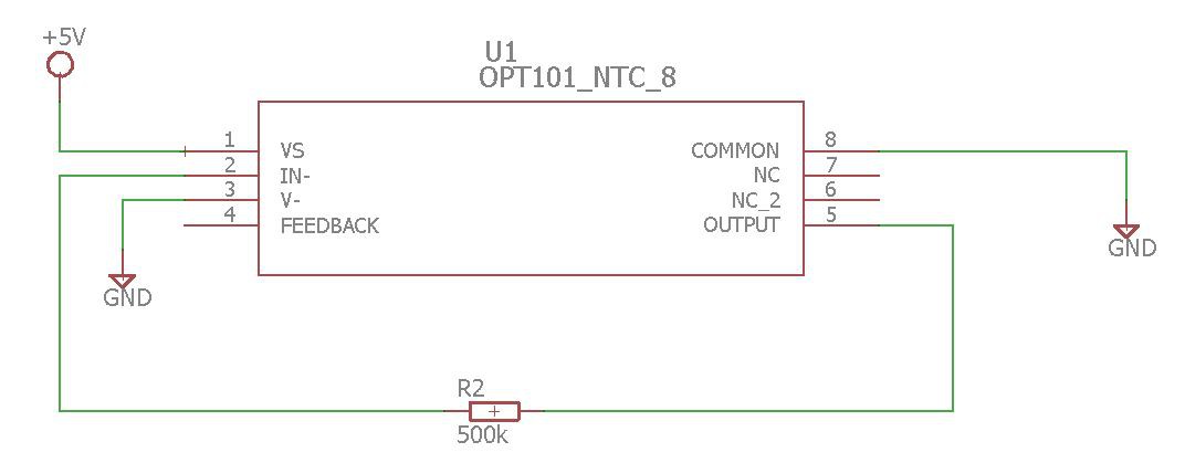 Here I don't care about the quantitative ripple reduction in absolute way, but more in a relative manner with respect to the solution with no ripple attenuation.
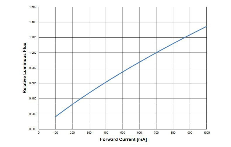 Still pretty linear I would say.