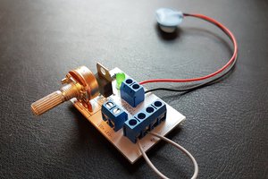
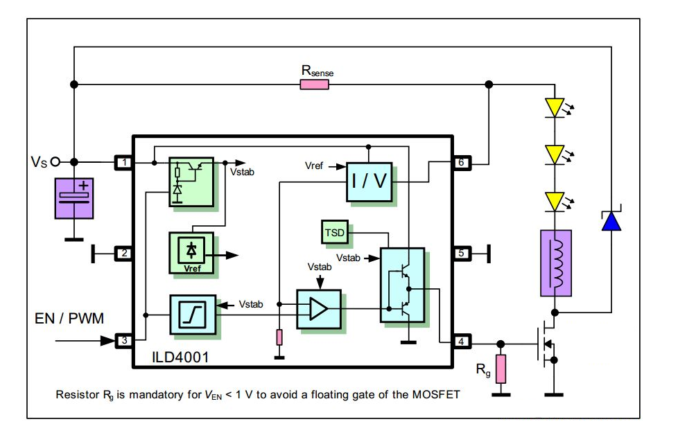
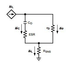
This project is a simple, yet efficient buck LED driver, or capable to provide basic constant current capabilities. Its existence is on the tail and for the same reasons of the Glighter-S module, but this was made to satisfy a compromise on another perspective: cost reduction and analog control vs. fixed frequency operation. This gives the need to pay more attention on filtering the output and is addressed in the project logs herein.
But has the enormous advantage to be so simple to build and being cheap with the same reliability of Glighter-S. I can now experiment more freely and use them as a jelly bean part for my LED projects.
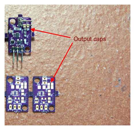
In the picture is quite clear that the module is smaller, since requires less parts, due to its intrisinc different, yet simple, technology of an hysteretic buck converter.
Project summary
- Technology: hysteretic buck regulator
- Input voltage: 2.5V+V_LED to 40V (V_LED the forward voltage of the LEDs)
- Output voltage: V_LED to 39V
- Sourced current: up to 900 mA (set by default to 640mA)
- Size: 13 mm x 21 mm (0.51 in x 0.83 in)
- Efficiency: up to 95%
- Operating Temperature: -40°C to 60°C
- Safety features:
- Short circuit immune
- Open circuit immune
- Safe state (off) when no control is applied
- Overtemperature protected (T < 120 °C)
- Control features:
- PWM control: voltage swing from <0.4V to >2.5V (safe up to input voltage supply), max PWM frequency 20 kHz
- Analog control: voltage swing from 0.4V to 2.5V for linear output current adjustment
- OFF: voltage < 0.4V
- Fully ON, max current set with sense resistor: voltage > 2.5V up to supply
- Other infos:
- Input impedace EN/REG pin: 39kΩ
- Max contrast ratio with PWM: 100:1
- Max contrast ratio with analog dimming: 6:1
- Max combined contrast ratio: 600:1
Source files
Any external link is shown in the project's links.
How to use it
The driver has 3 input pins
- VIN: the input voltage
- GND: ground
- EN/REG: the control pin (analog+PWM) and enable pin
Any board handling any type of digital signal can be used to drive the EN/REG pin. Any signal lower that 0.4V result in a full off driver; any signal higher that 2.5V fully turns on it. Analog signal can be safely used.
The output is made by 2 pins
- LED anode
- LED cathode
Just connect the LED respecting the polarity, or the LED can fail.
Setting the current
Assuming that the input voltage is respected, the driver can light any LED which is designed to take around 640mA, or lower, if proper analog dimming is provided. By changing the sense resistor, the maximum current can be increased up to 1A. Can also be reduced to increse the analog resolution of the output current.
I made this resistor fixed (but interchangeable) for a security reason: avoid wrong configurations. The driver uses a sense voltage Vsense = 0.121 V. The maximum output current shall be sey by I = 0.121V / R.
 Enrico
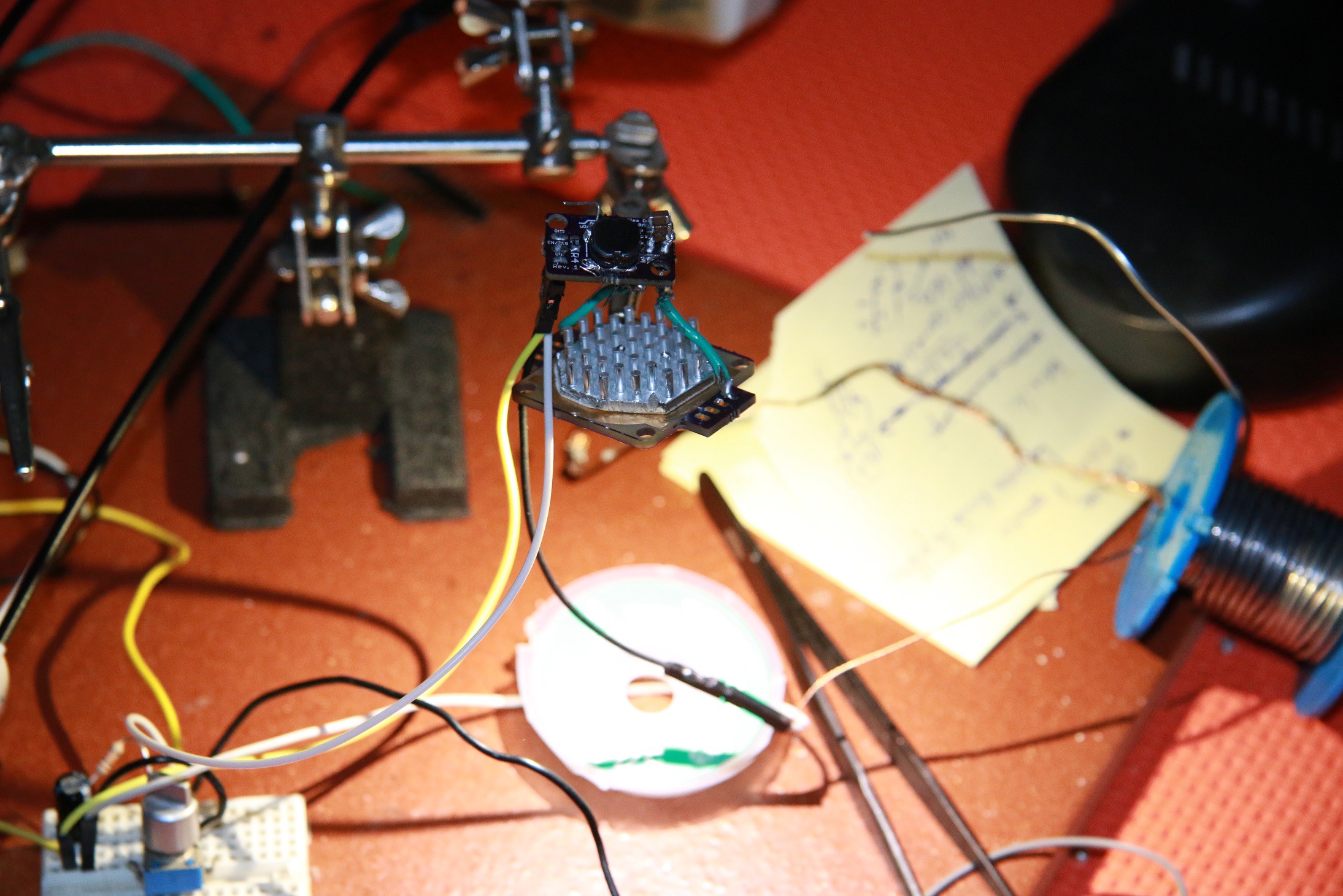
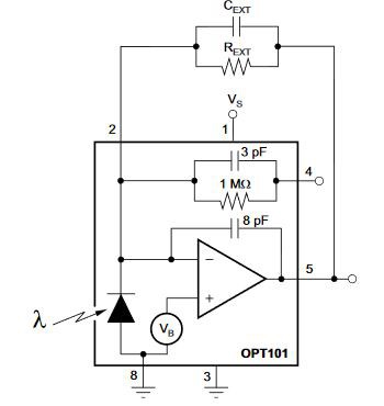
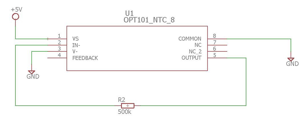
 Since I don't have any capacitor with me and 1M of gain bring a 23 kHz of bandwidth, a gain 500k could set the game of a bandwidth between 44 kHz and 23 kHz, without making stability issues. Therefore the only output component was a 500 k
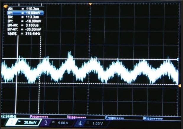
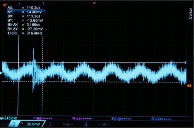
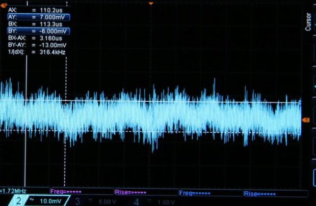
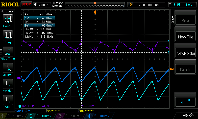
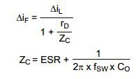
 Here I don't care about the quantitative ripple reduction in absolute way, but more in a relative manner with respect to the solution with no ripple attenuation.
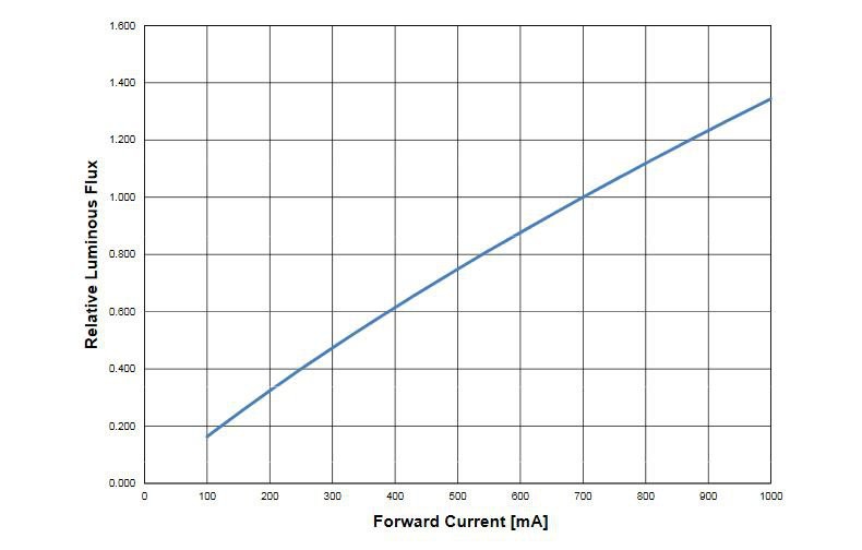 Still pretty linear I would say.


 Hulk
Hulk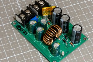
 Kevin LO
 Christoph Tack