Cedric Anné
-
The finish line... kind of
09/13/2019 at 16:23 • 0 commentsSince the last log, I finished this build. It took me 4 days total to get everything right and I didn't keep good documentation on anything, including the 3d files, so I'm not entirely sure they are the best versions... but I'll try and fix that later.
I'm just going to go through building this damned thing step by step, here it goes:
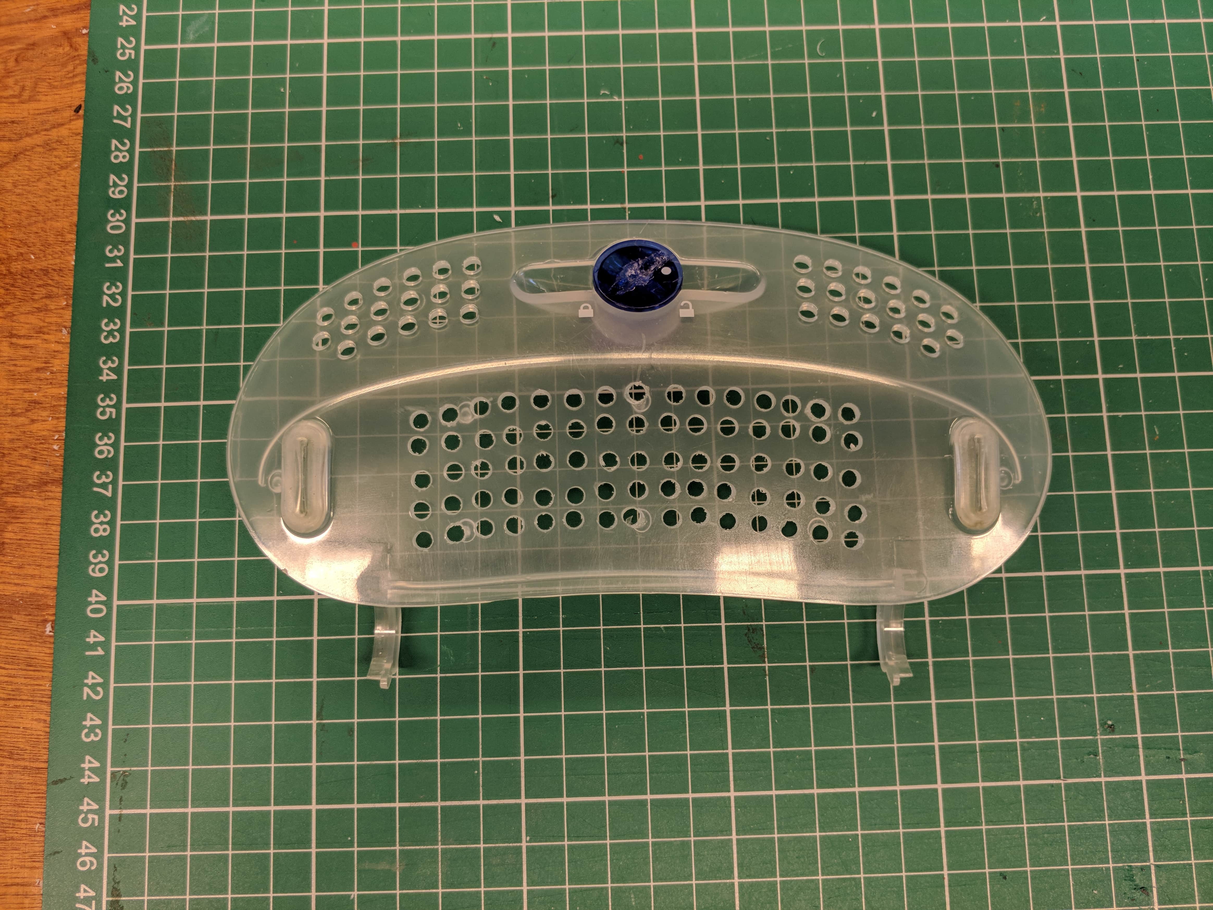
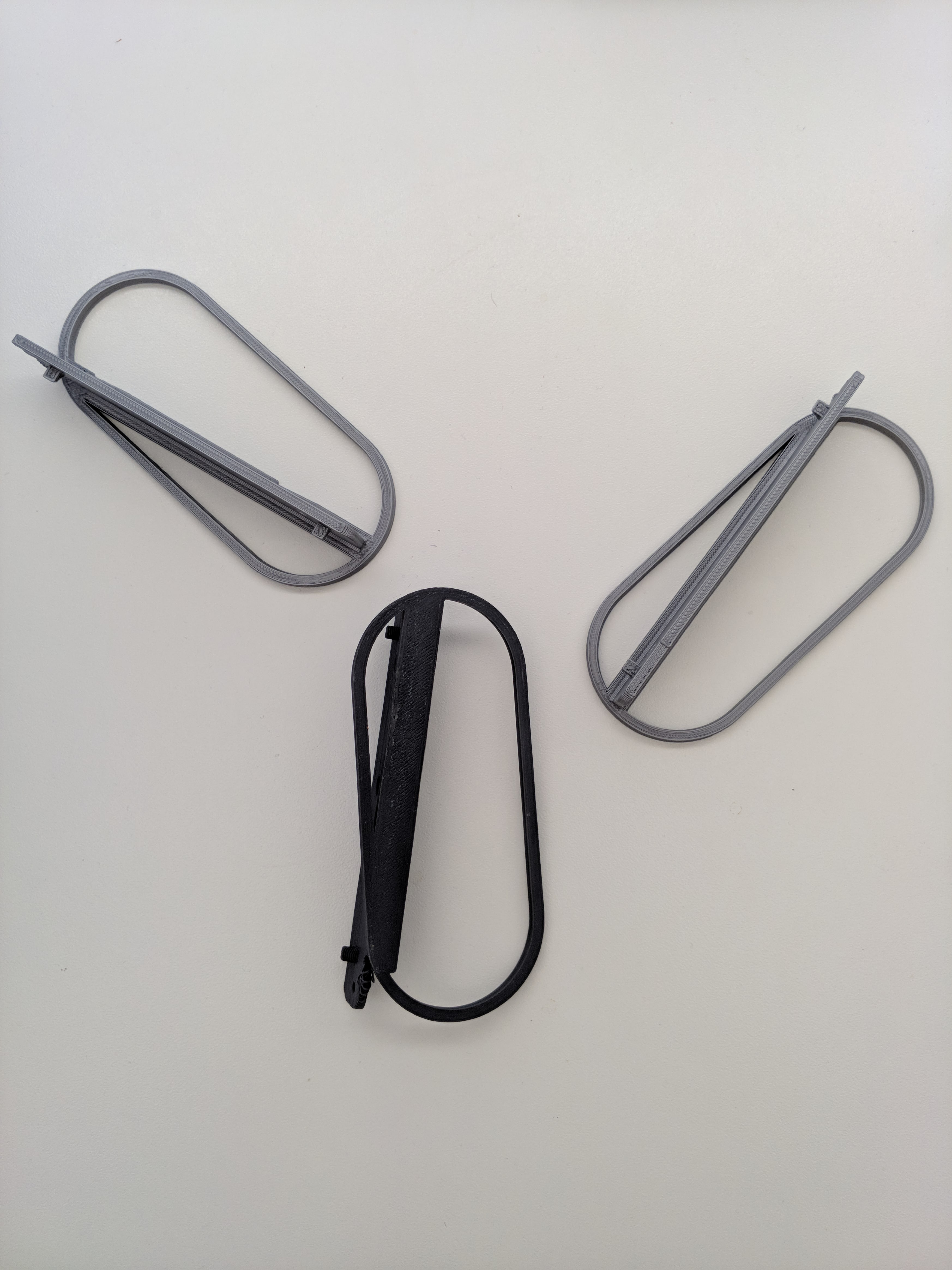
- For some extra ventilation on top, I added holes in a concentric pattern to the bulbous thing on the inside of the handle.
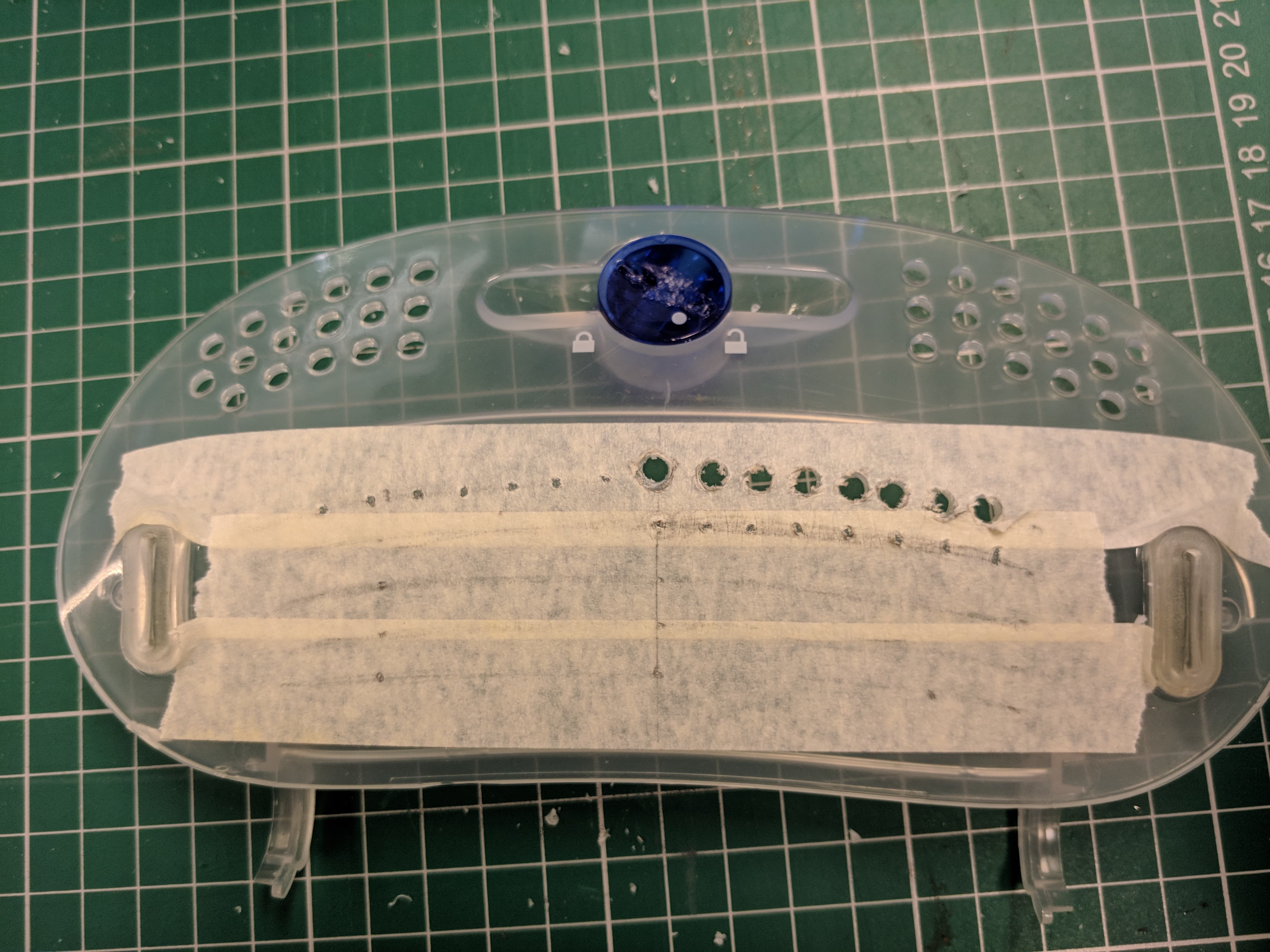
![]() I tried measuring by hand, but that turned out to be a hasstle, so I made a template (like one on those strands of people holding hands you make as a kid) that would show me where to drill holes in a hexagonal pattern.
I tried measuring by hand, but that turned out to be a hasstle, so I made a template (like one on those strands of people holding hands you make as a kid) that would show me where to drill holes in a hexagonal pattern.![]() The finished product should look something like this (this is with the arms for the 200mm fan attached).
The finished product should look something like this (this is with the arms for the 200mm fan attached).![]()
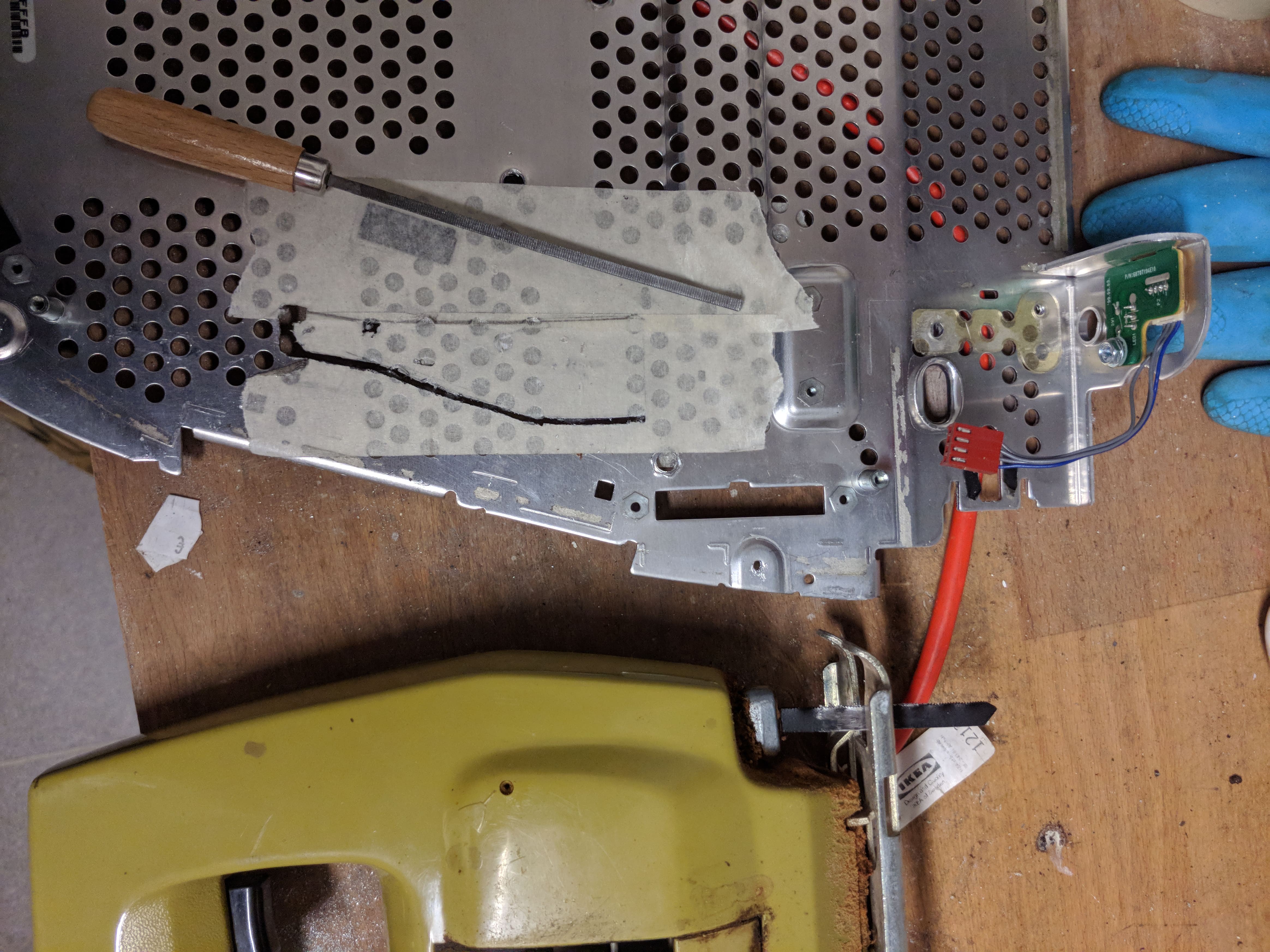
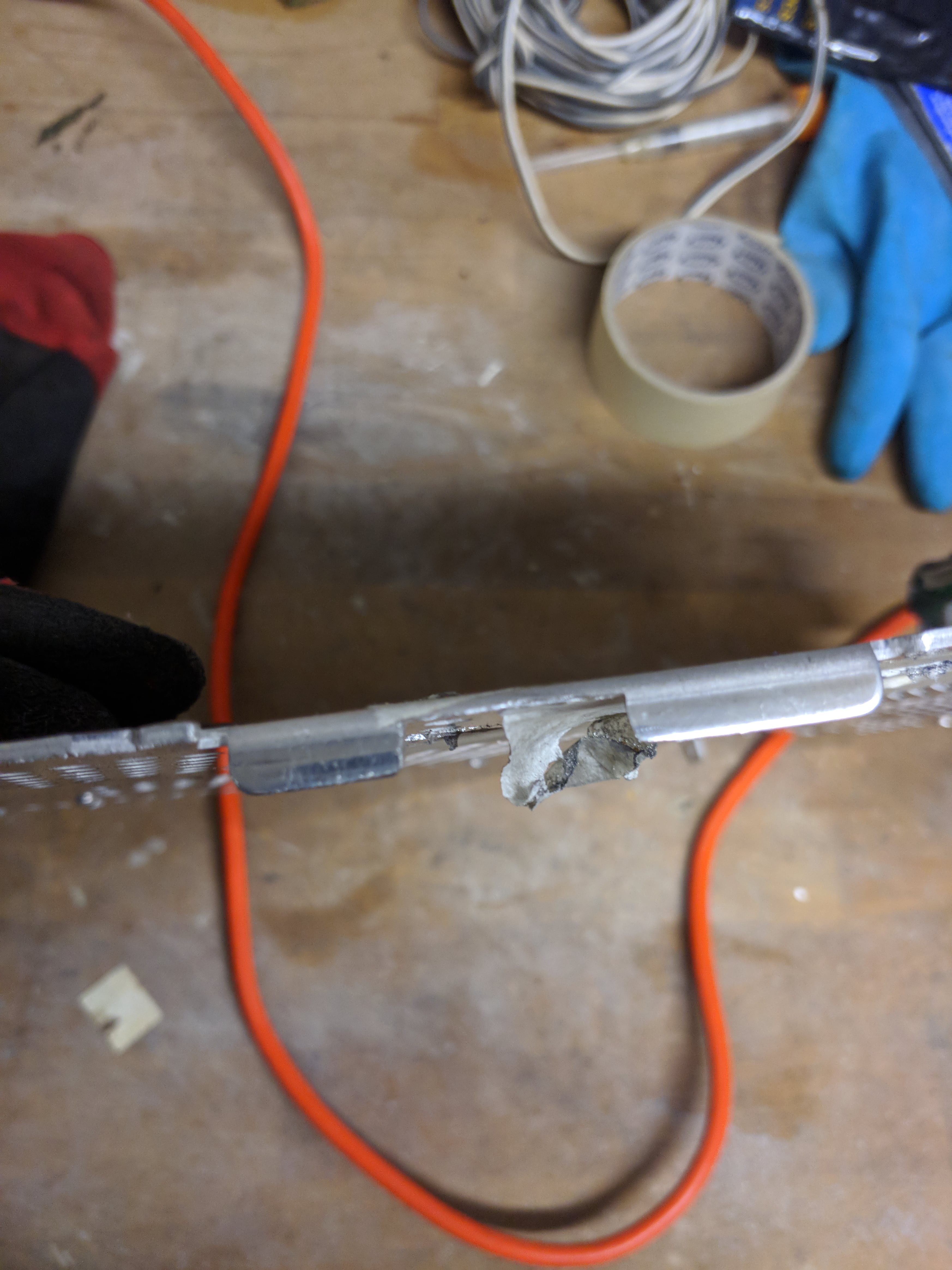
Next up: Drilling and sawing holes in the metal baseplate to route cables. This was easier than I expected, just took some elbow grease but apparently aluminum is quite soft.
![]()
Be sure to use a jigsaw or handsaw and not a dremel though, because as it turns out, aluminum dust is toxic and might explode!
![]()
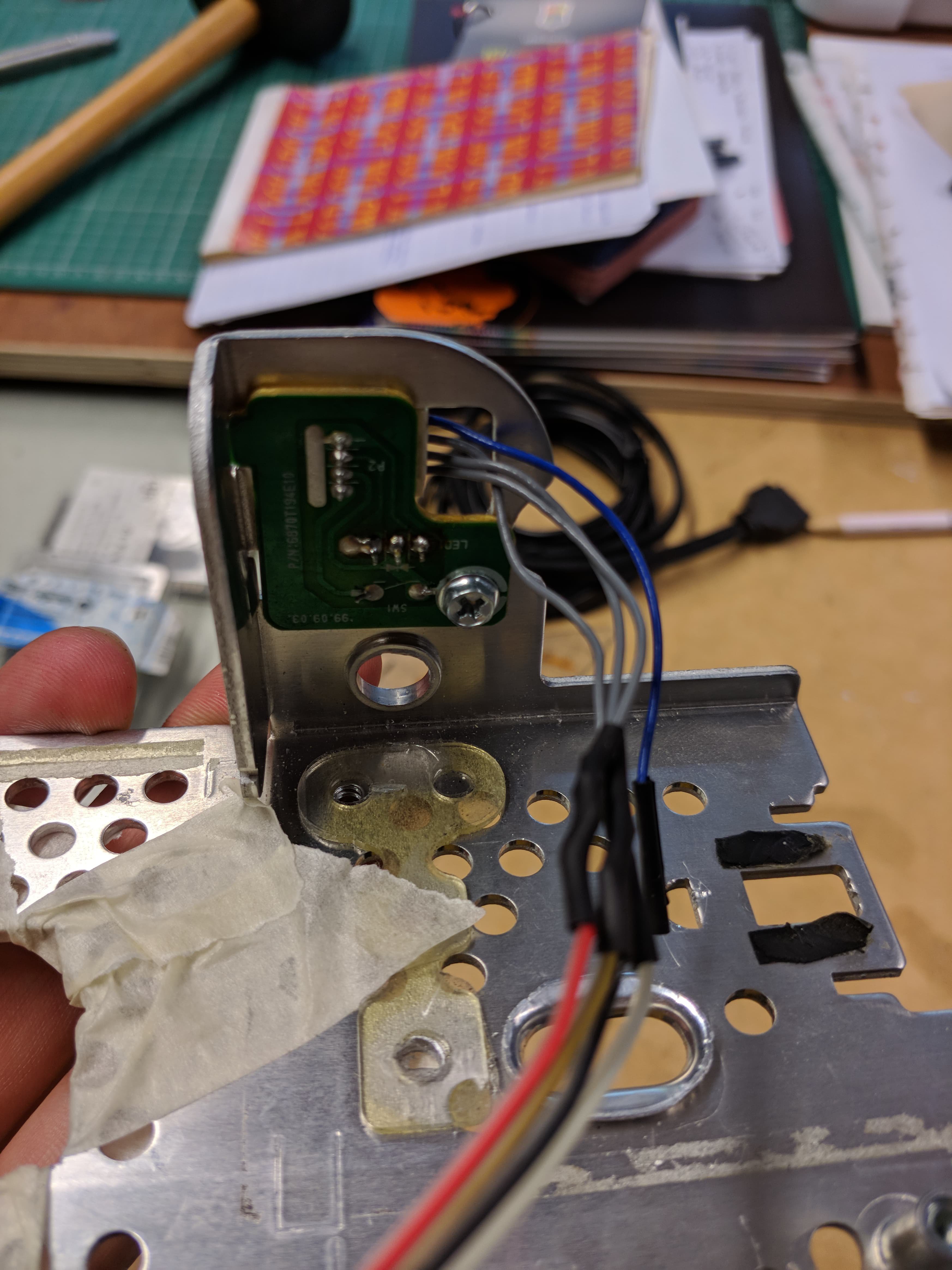
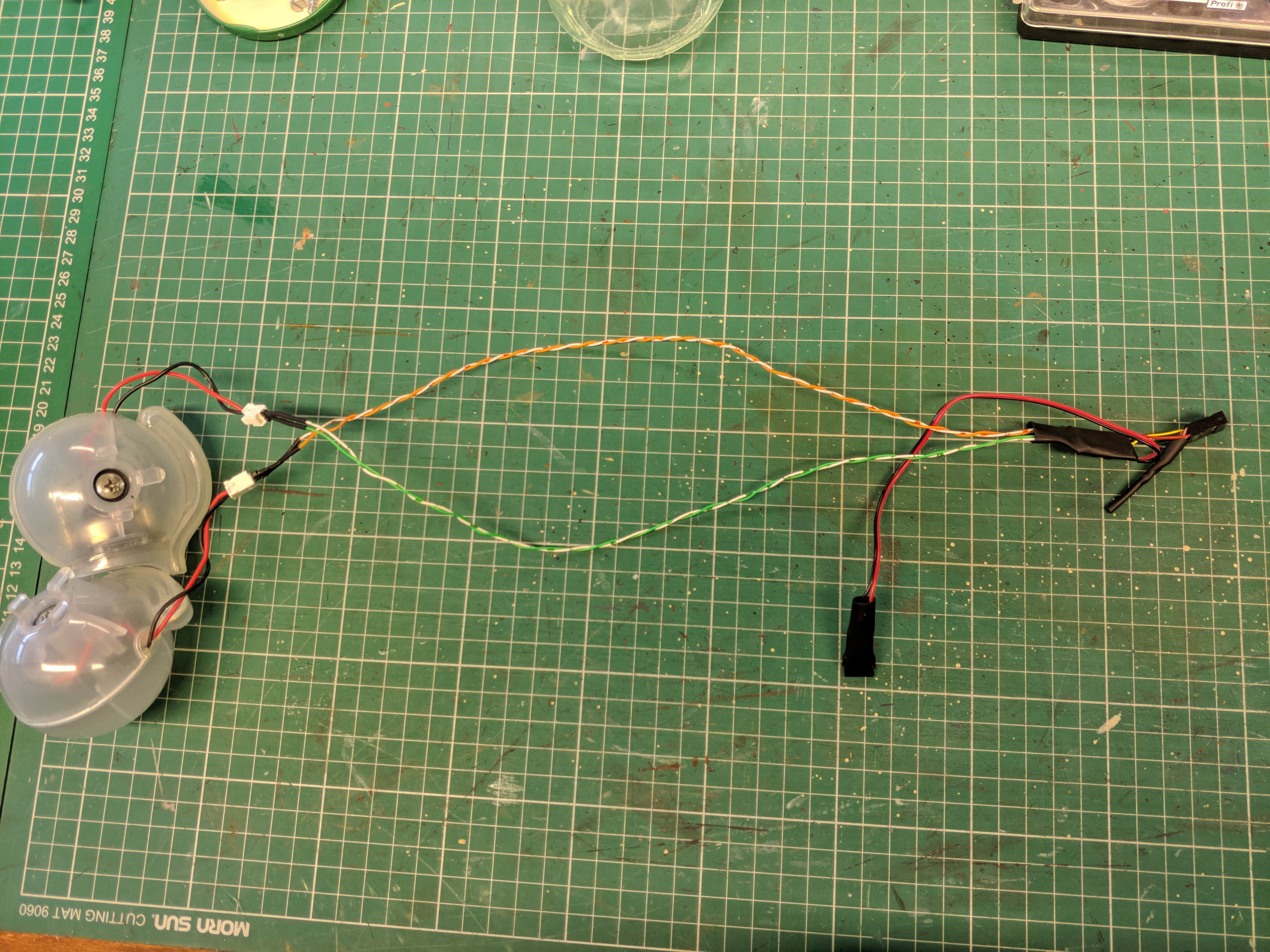
After that I made some cables. I connected the old iMac's power button and power led to some female headers, easy enough. I didn't want to try and figure out what all the circuitry on the headphone jacks was about, so I didn't even try to hook that up. (Although I think it's just a sense circuit, so you might be able to use it with an HD audio connector)
![]()
The speakers also needed a cable. I tried to plug them in to the HD audio connector on the motherboard and that really wasn't loud enough, so I used a PAM8304 breakout board I got on aliexpress and powered that using the D_LED header on my motherboard.
![]()
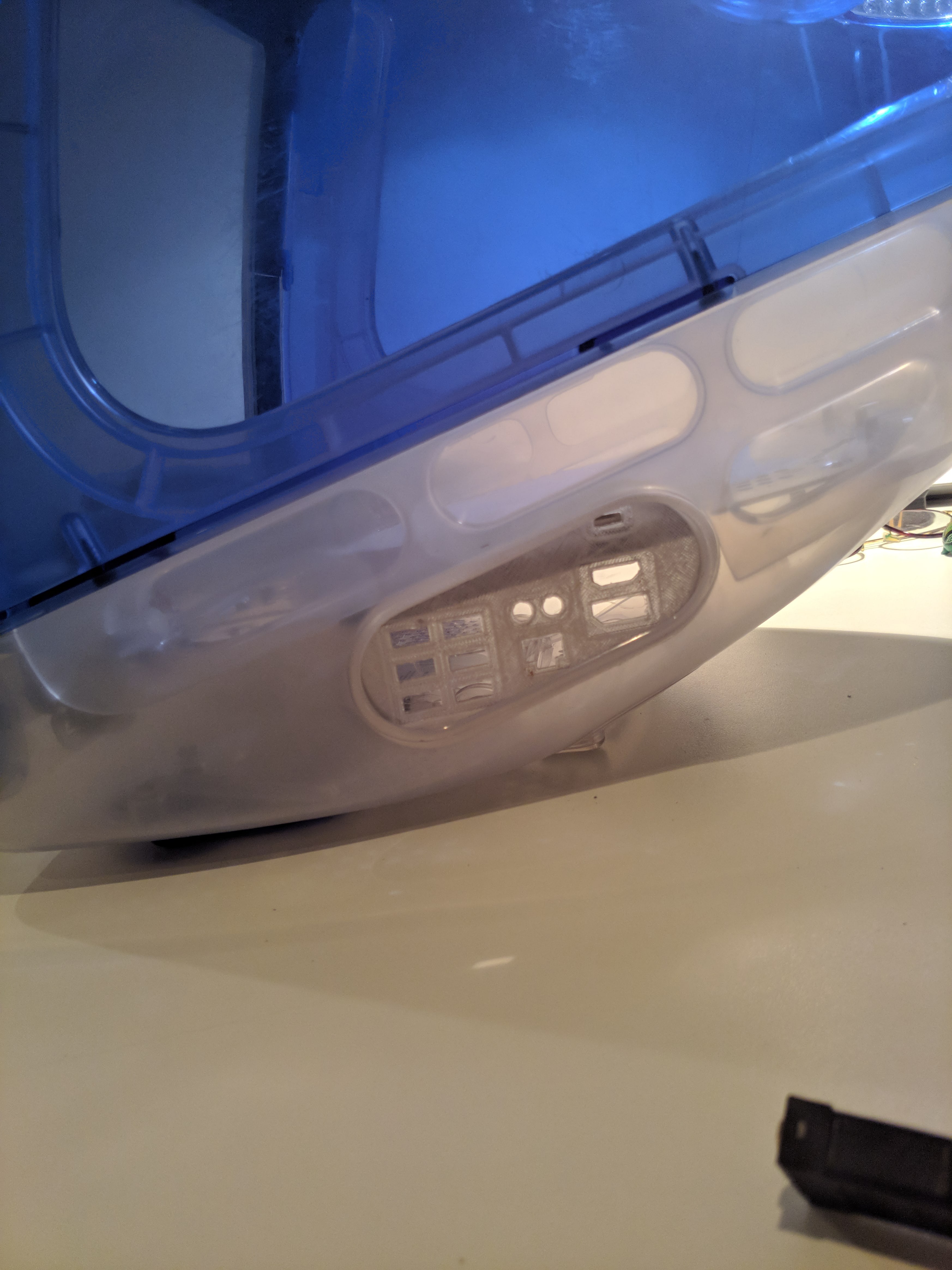
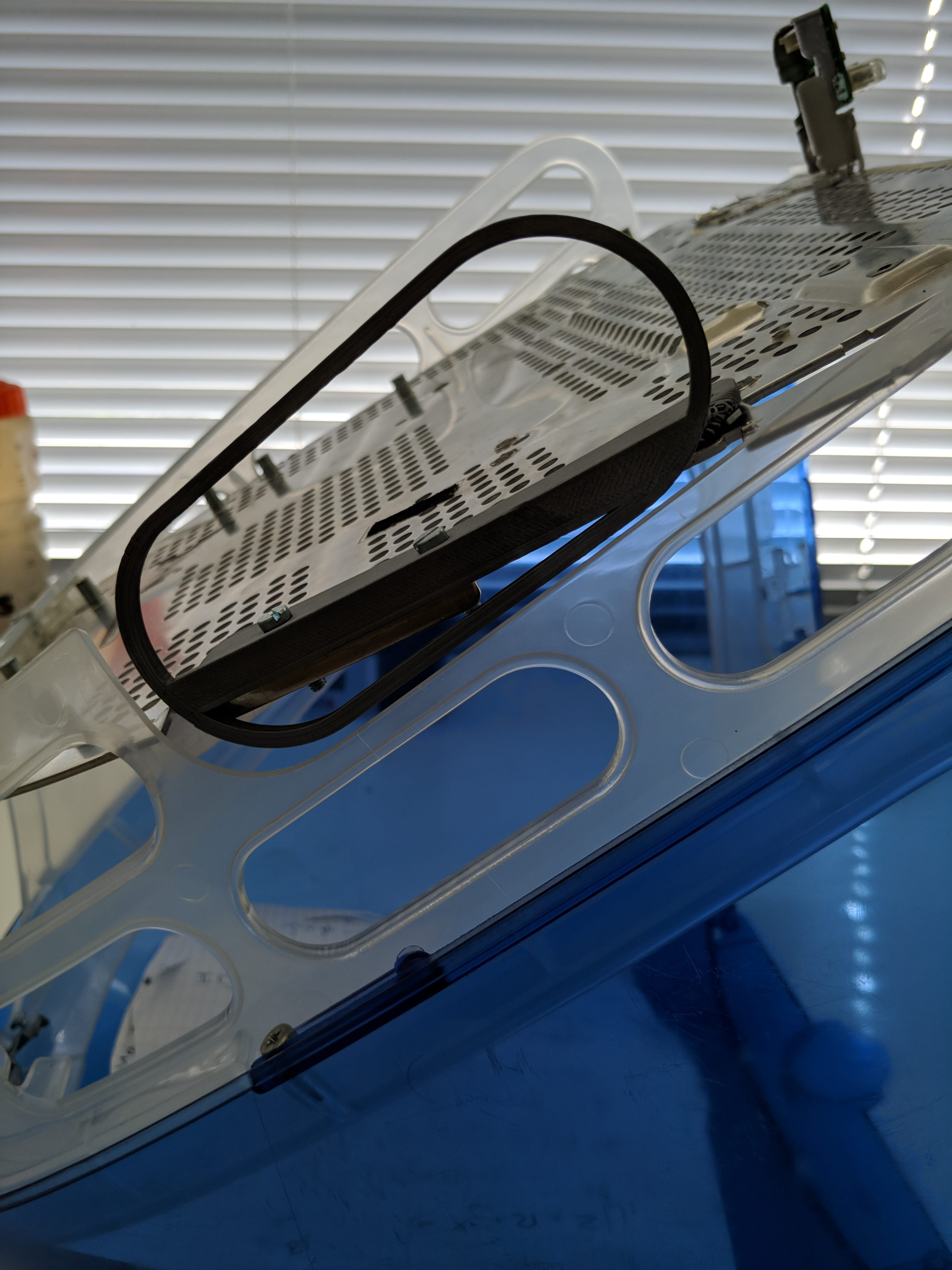
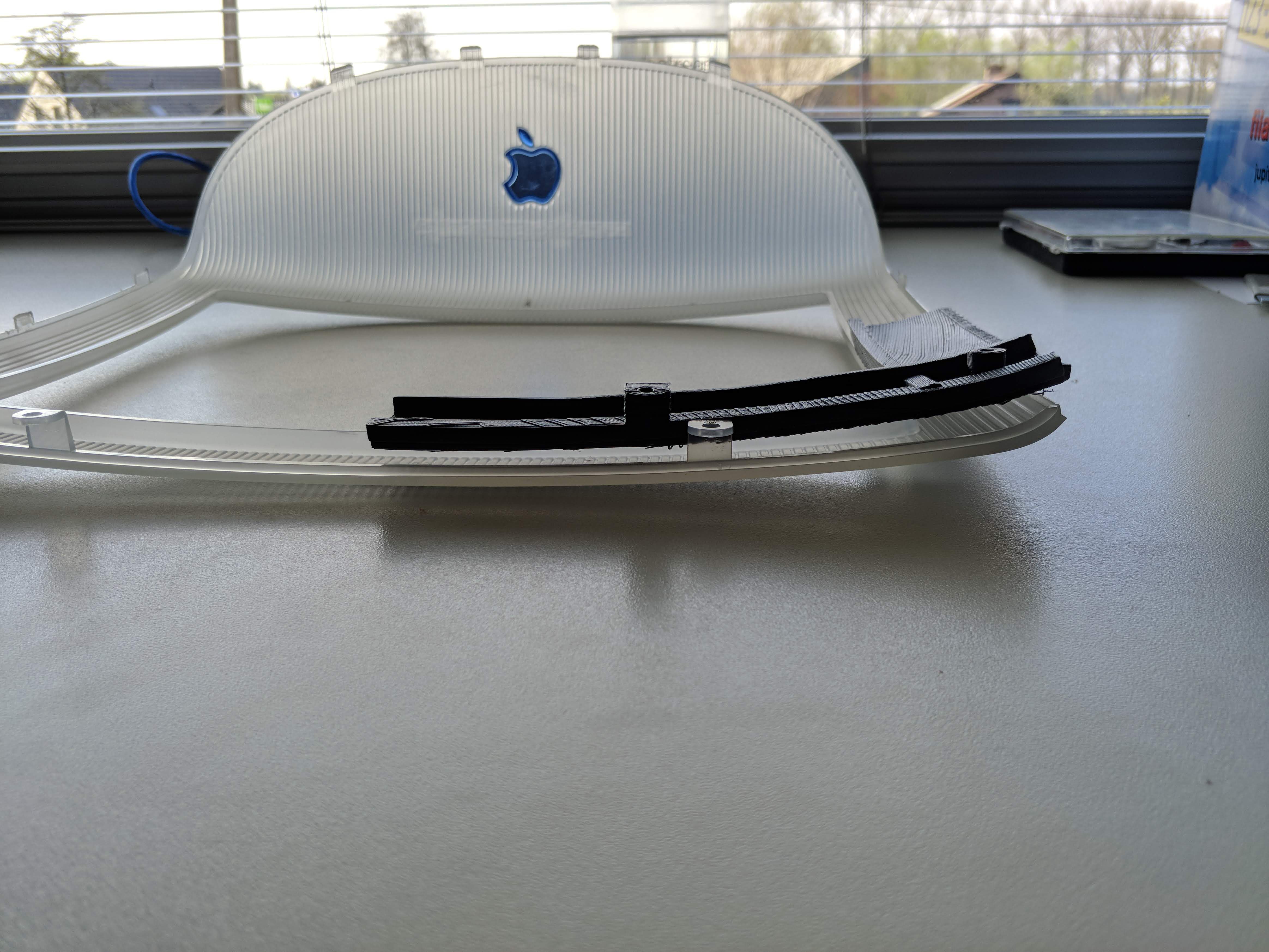
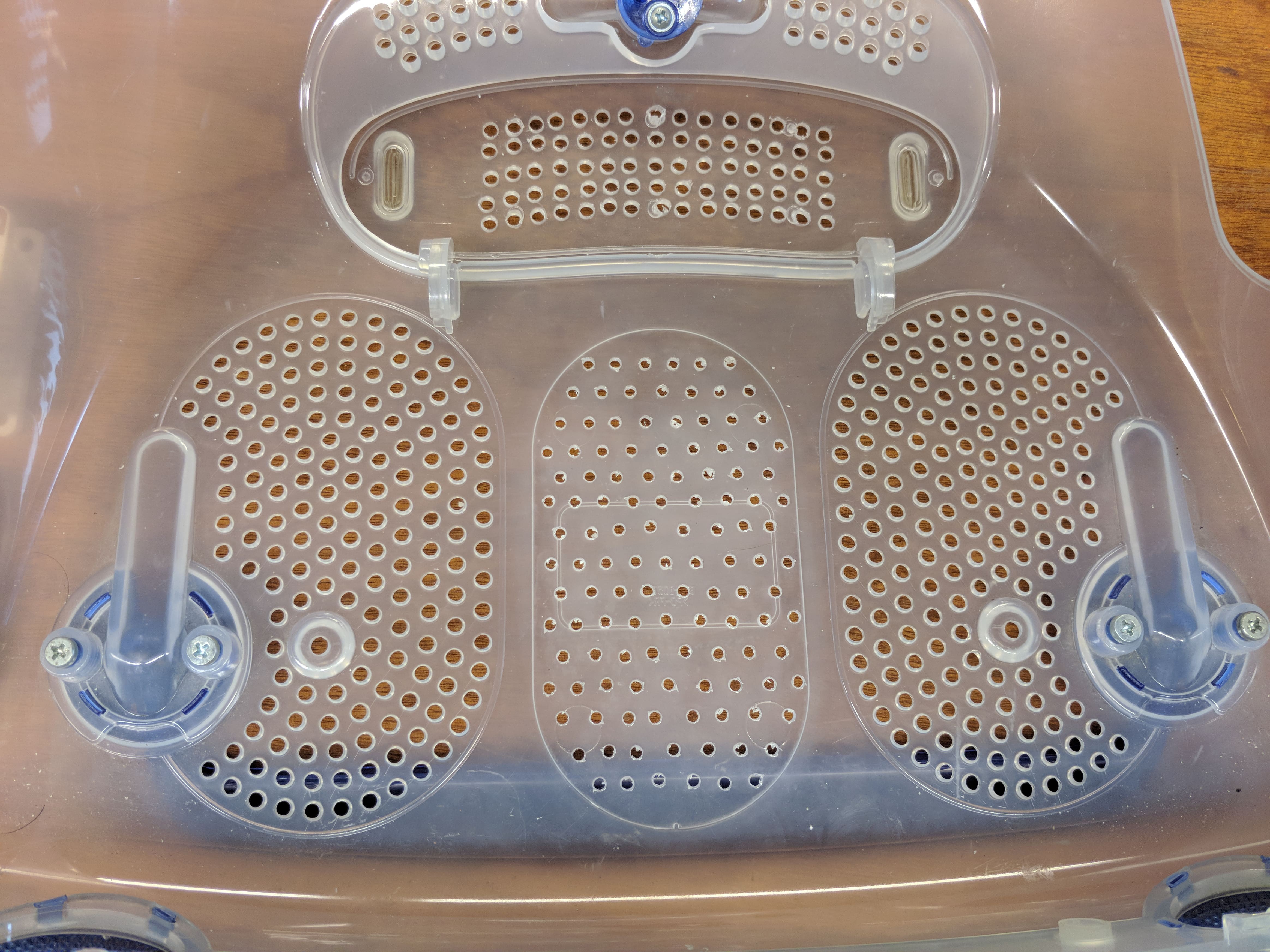
Last place to drill some holes was on the bottom of the plastic chassis for the GPU. I chose a blower style GPU so it would have it's own separate airflow from bottom to back. I used the same stencil for this as for the top fan.
![]()
I think that was most of the chassis work (apart from some holes you need to drill...) so now, with all the 3d printed parts, I think we're ready to assemble.
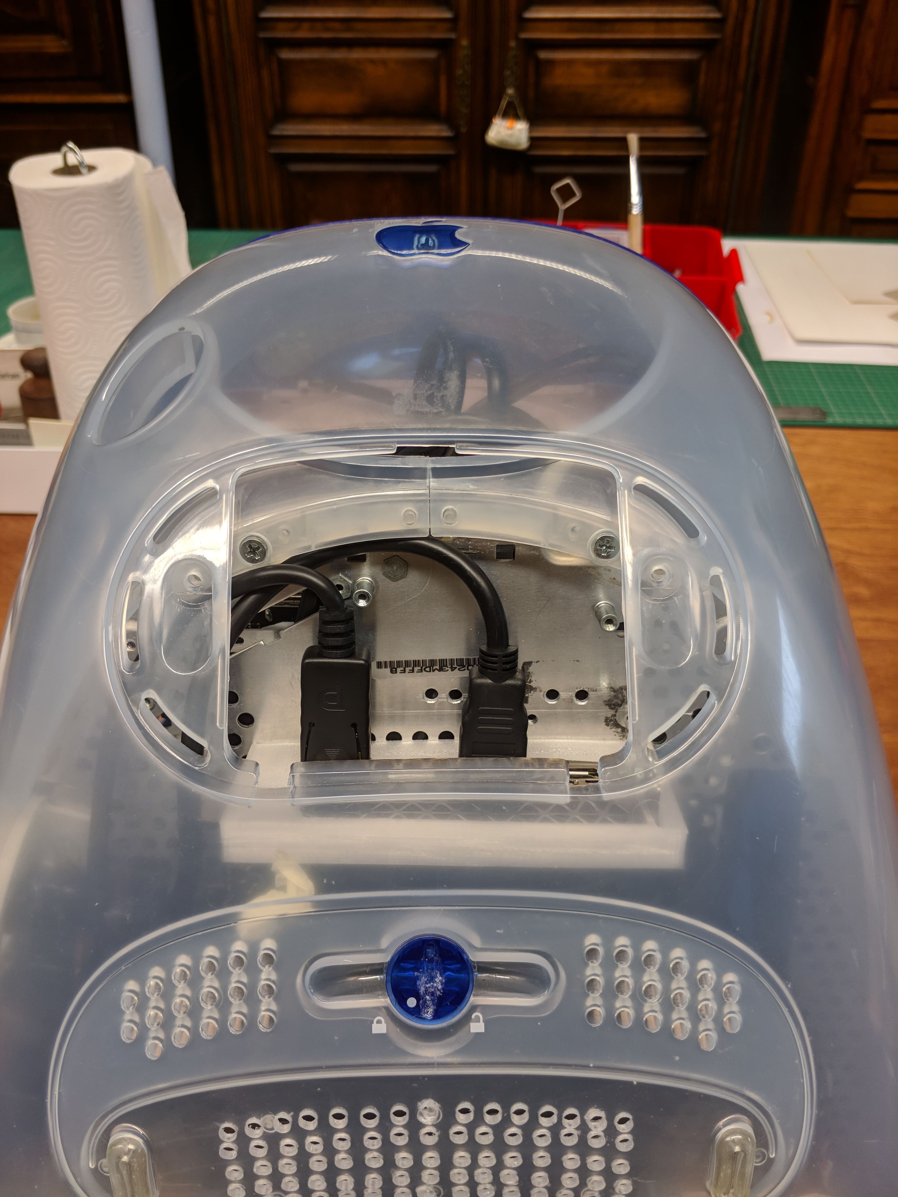
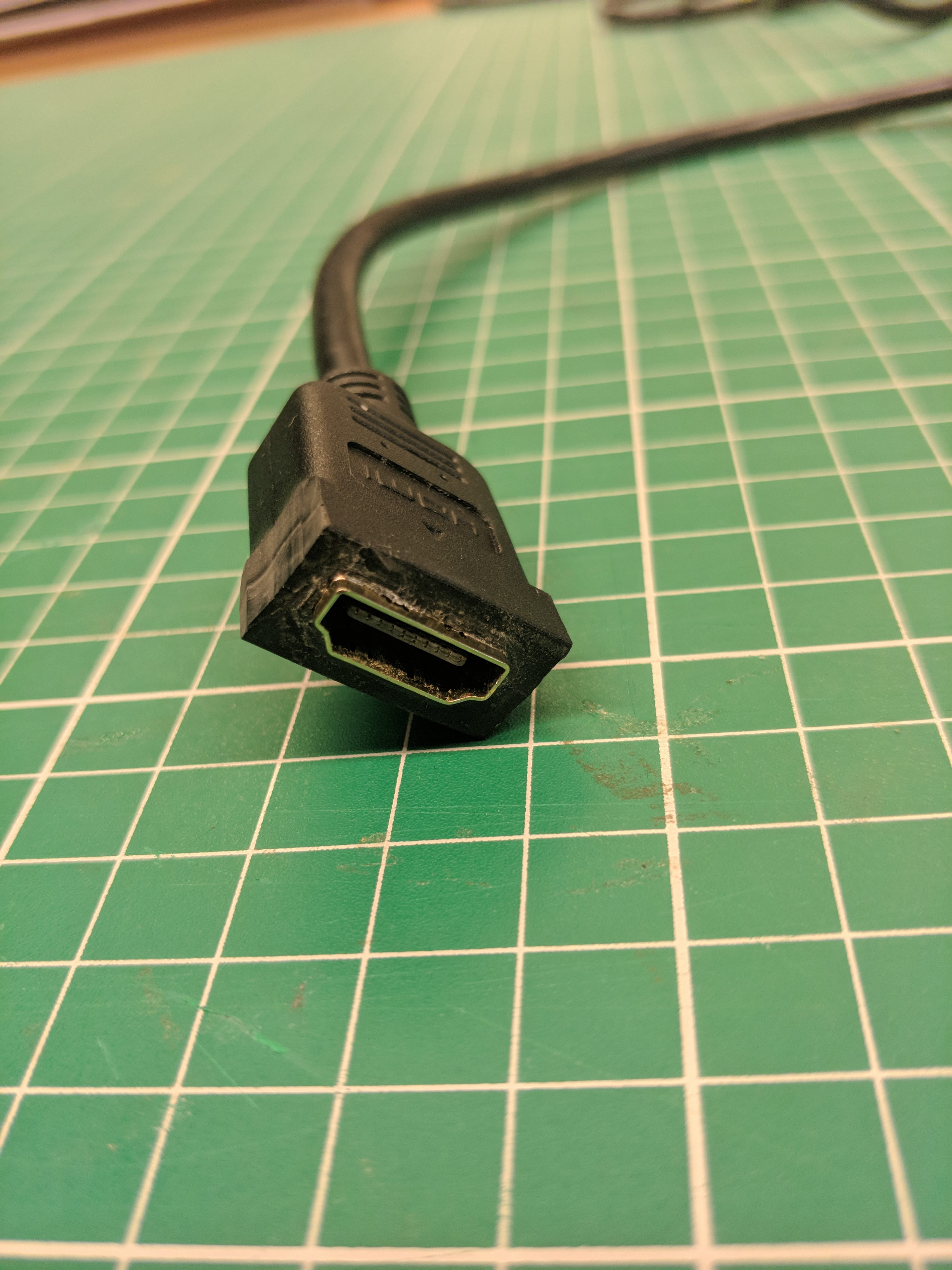
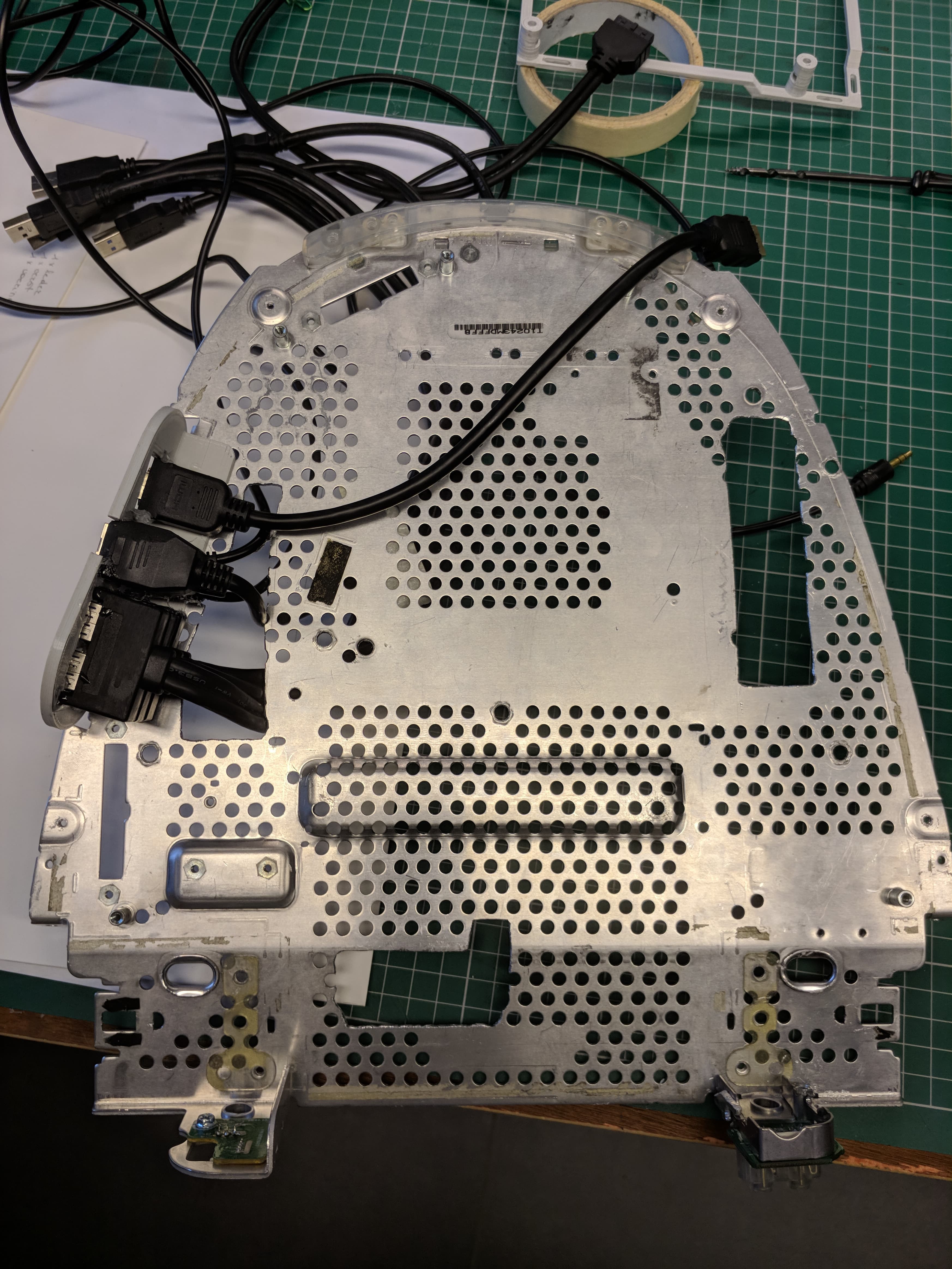
First up is the IO bracket. I glued all the cables in place with some transparent epoxy. Due to bad design, the USB-C connector on the top could only go in after this thing was already mounted to the metal baseplate and to make things worse, one of the two screws holding that in place was also in the way... It did work out in the end though, just needed to scrape some plastic off the connector and convince it to stay in place for long enough. You should end up with something like this.
![]()
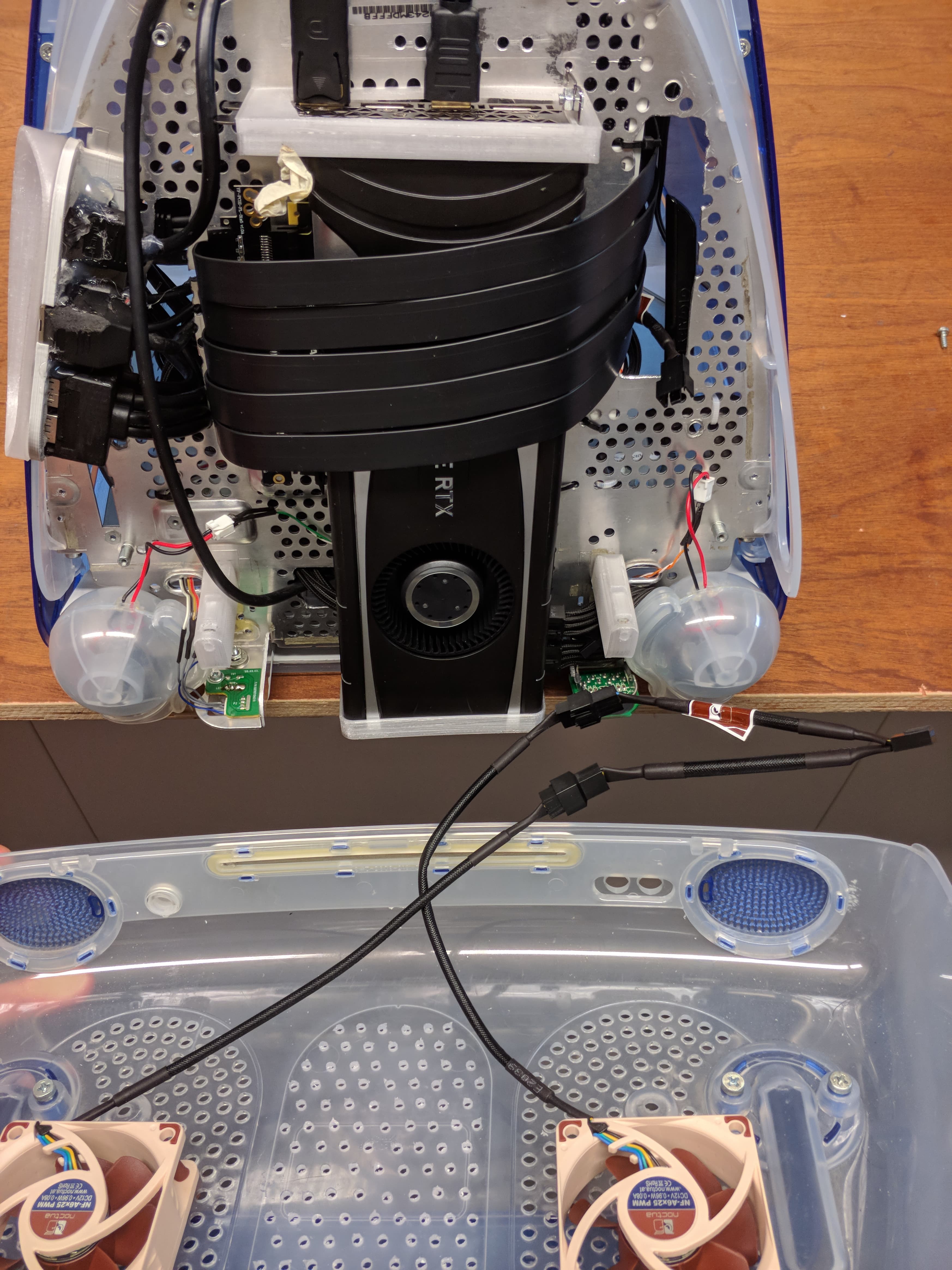
With that out of the way (more like in the way) It's time to mount the GPU. I tried a lot of versions of my models on this and in the end one of them worked out, but it sure wasn't pretty and even less easy to install.
![]() The front (directed towards the back of the iMac) wasn't that bad. The back however...
The front (directed towards the back of the iMac) wasn't that bad. The back however... ![]()
![]() As you can see I used metal brackets on this one instead of 3d printed angles. That's because the PETG I was printing in kept breaking on that spot and this was on day 4 and I got tired of waiting for the printer. I might update the model (this is also a model with a part cut off and holes drilled into it)... or I might not... We'll see :P
As you can see I used metal brackets on this one instead of 3d printed angles. That's because the PETG I was printing in kept breaking on that spot and this was on day 4 and I got tired of waiting for the printer. I might update the model (this is also a model with a part cut off and holes drilled into it)... or I might not... We'll see :PWith the GPU in place this might be the time to finish everything on the bottom. Add the speakers and bottom chassis connectors now. This may be a little hard because they're all very close together, but it should work out fine.
![]() When adding in the GPU it's also important to have the power cable and PCIe extension already plugged in. It's so tight in there that I couldn't get to the connectors when it was screwed in.
When adding in the GPU it's also important to have the power cable and PCIe extension already plugged in. It's so tight in there that I couldn't get to the connectors when it was screwed in.On to the top: cable manage all those cables from the IO shield underneath the motherboard mount and zip-tie that in place.
![]()
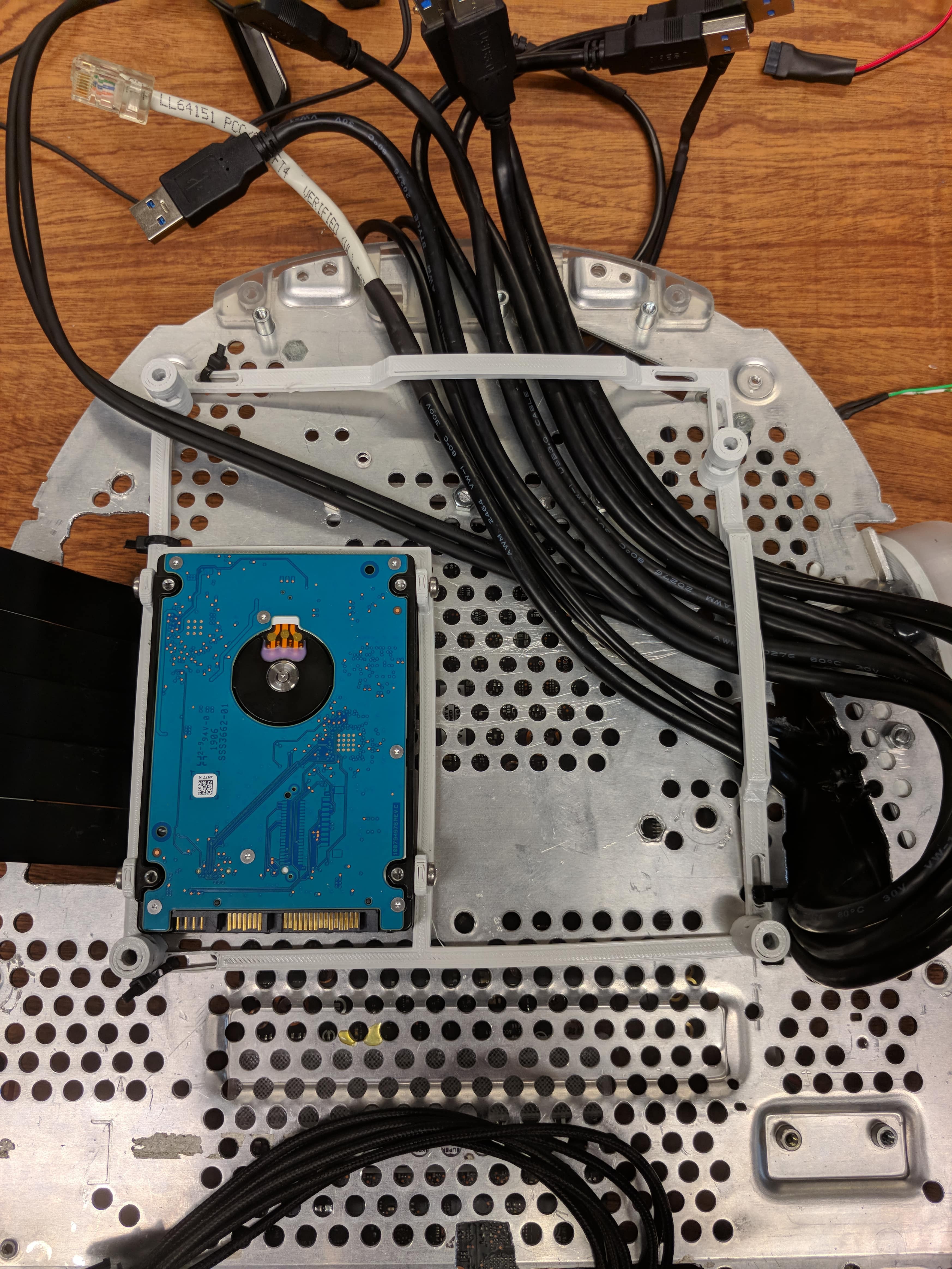
Now is the time to add your HDD (or not, I'd recommend not to, you'll see why later on...)
![]()
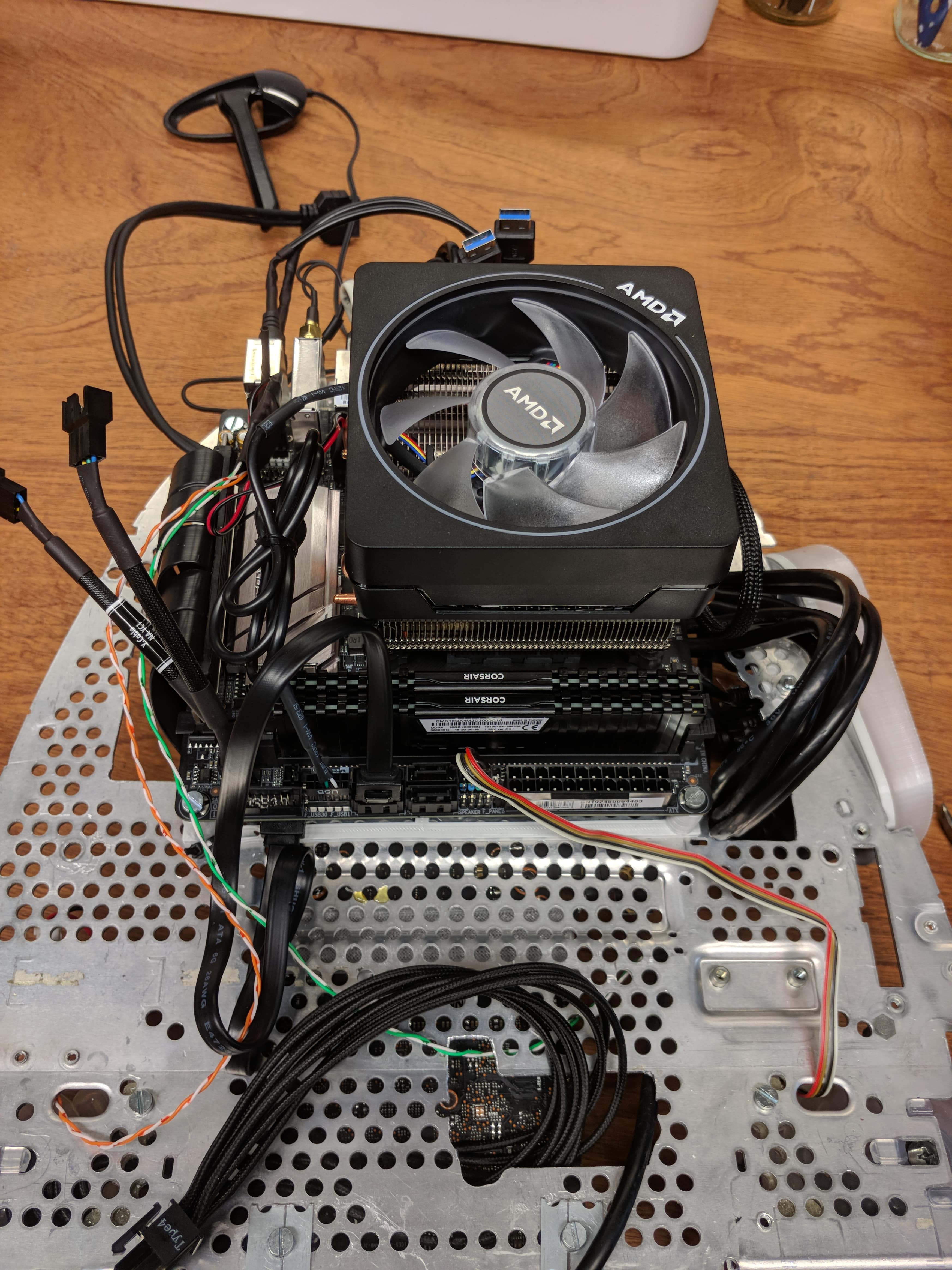
And then screw in your motherboard.
![]()
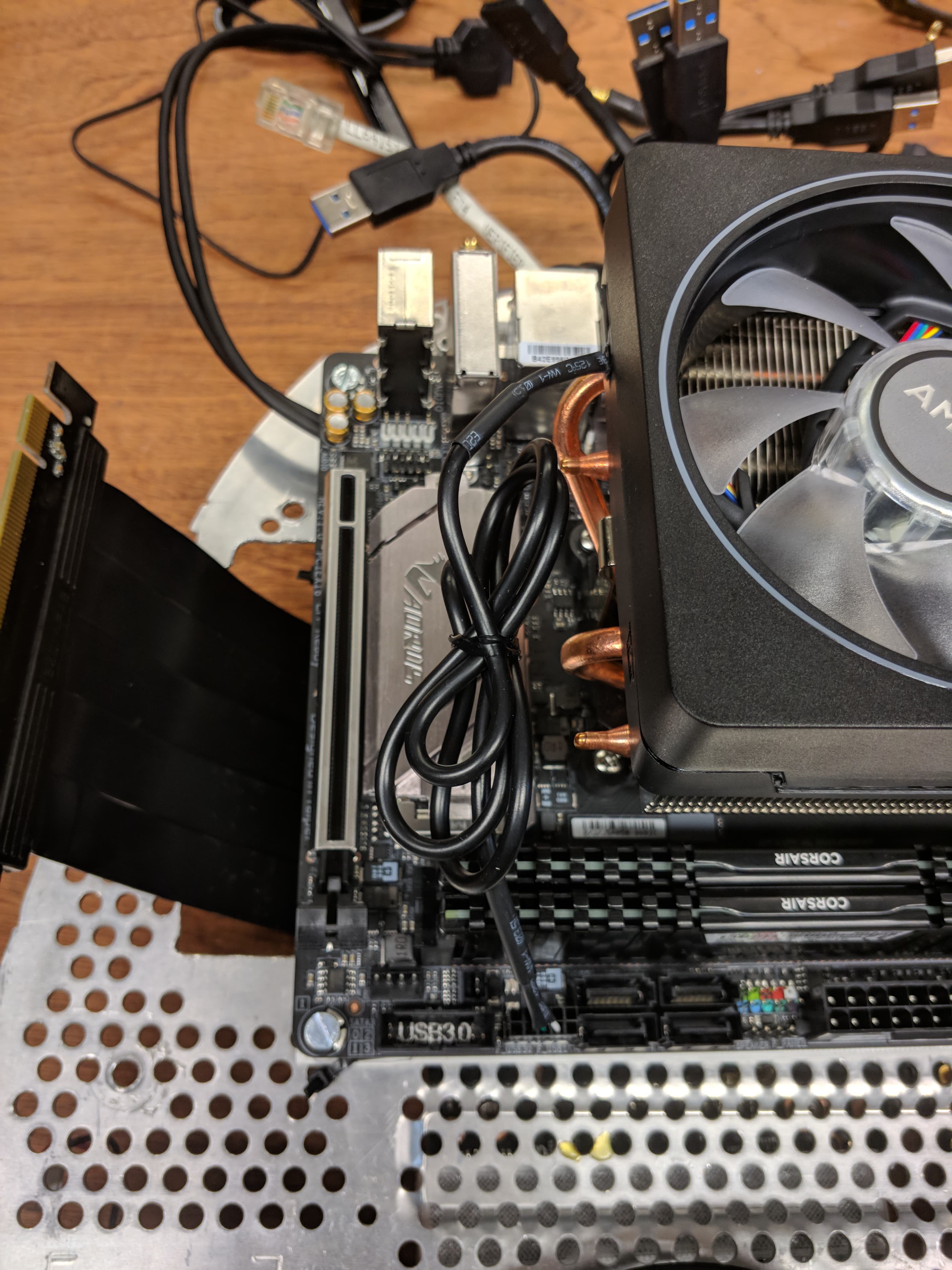
Plug in all your cables (PSU, PCIe, fan headers/splitters, all the IO, power button and speakers) and maybe take it for a spin, to see if all your expensive computer parts still work. You can still get to them now.
![]()
![]() If you have it, also add the wifi antenna.
If you have it, also add the wifi antenna. ![]() And then try and manage those cables as best you can. I promise it won't be easy ;)
And then try and manage those cables as best you can. I promise it won't be easy ;)Now that everything important is on there (you've confirmed it still works!) and you think it looks clean enough, mount the top fan on the top plastic chassis like so:
![]()
![]()
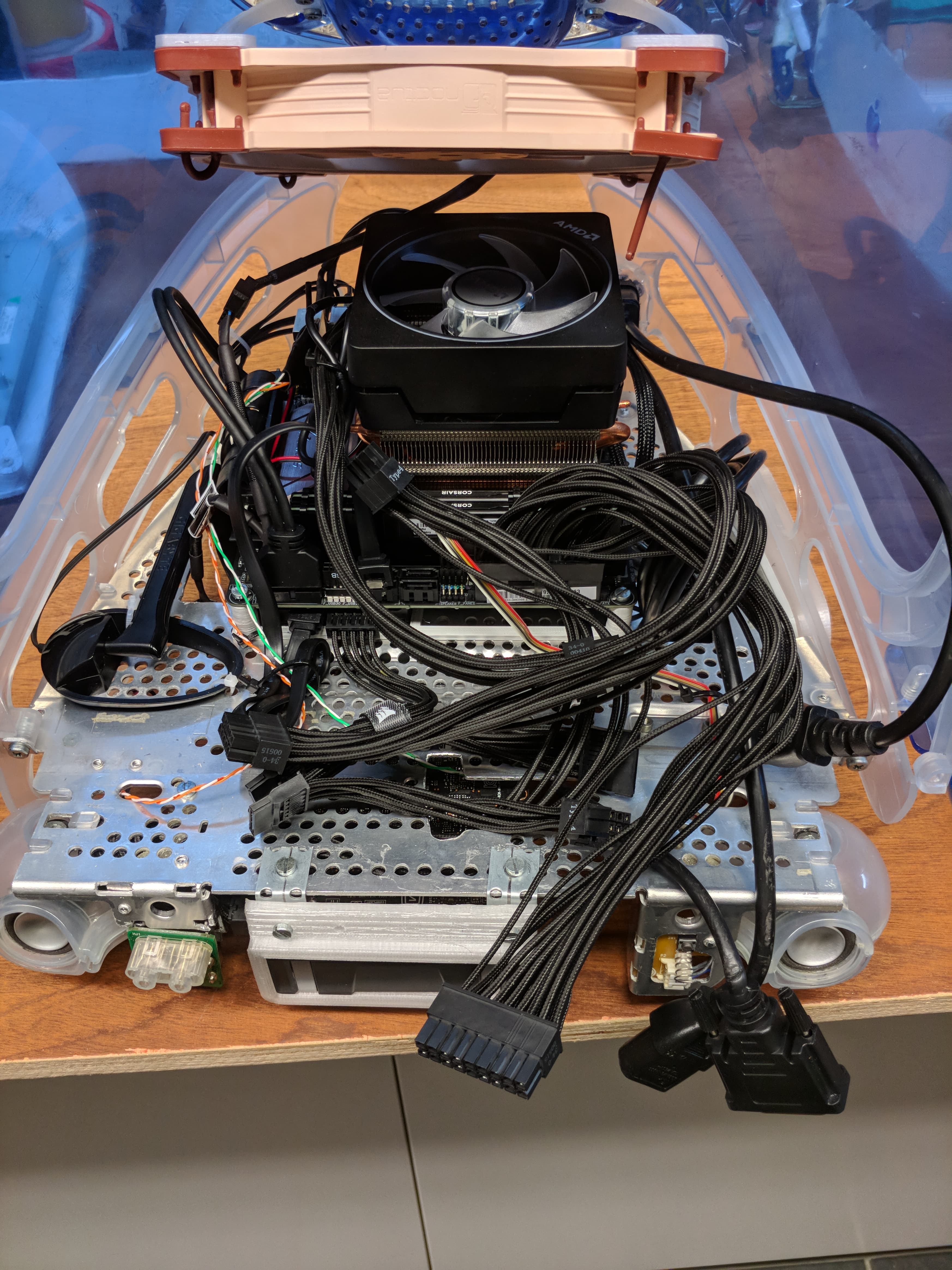
That's the top done, now screw it down to our metal base. My power splitter cable was too big and needed a little shave so it wouldn't bump into the CPU power connector on the motherboard.
![]() There's 4 screws to get here: 2 on the front
There's 4 screws to get here: 2 on the front ![]() and 2 on the back.
and 2 on the back. ![]() It should just pop into place with those 2 tiny plastic alignment bumps.
It should just pop into place with those 2 tiny plastic alignment bumps.I don't have pictures of this, but here is the time you want to glue the IO shield front to the mount. Try and fit it in the bottom chassis and glue it down. I used hot glue and it worked pretty well.
On to the PSU and screen. I think I detailed the screen in the last log. It's easy enough, just lay it down flat and screw in the mounting brackets to keep it in place. My screen has VESA mounting holes on the back, so I'm screwing in my PSU there. There's 4 little plates that give me enough room to do that.
![]() These models are also not correct, because I had to rotate the PSU to fit inside. I might still change the models on github.
These models are also not correct, because I had to rotate the PSU to fit inside. I might still change the models on github. Screw in your power supply (these brackets were also wrong so I used a dremel to fix them. I think those are already fixed in fusion360, but I haven't actually confirmed that they work). Now screw it all together. (for me with the power input on top and output on the bottom)
![]()
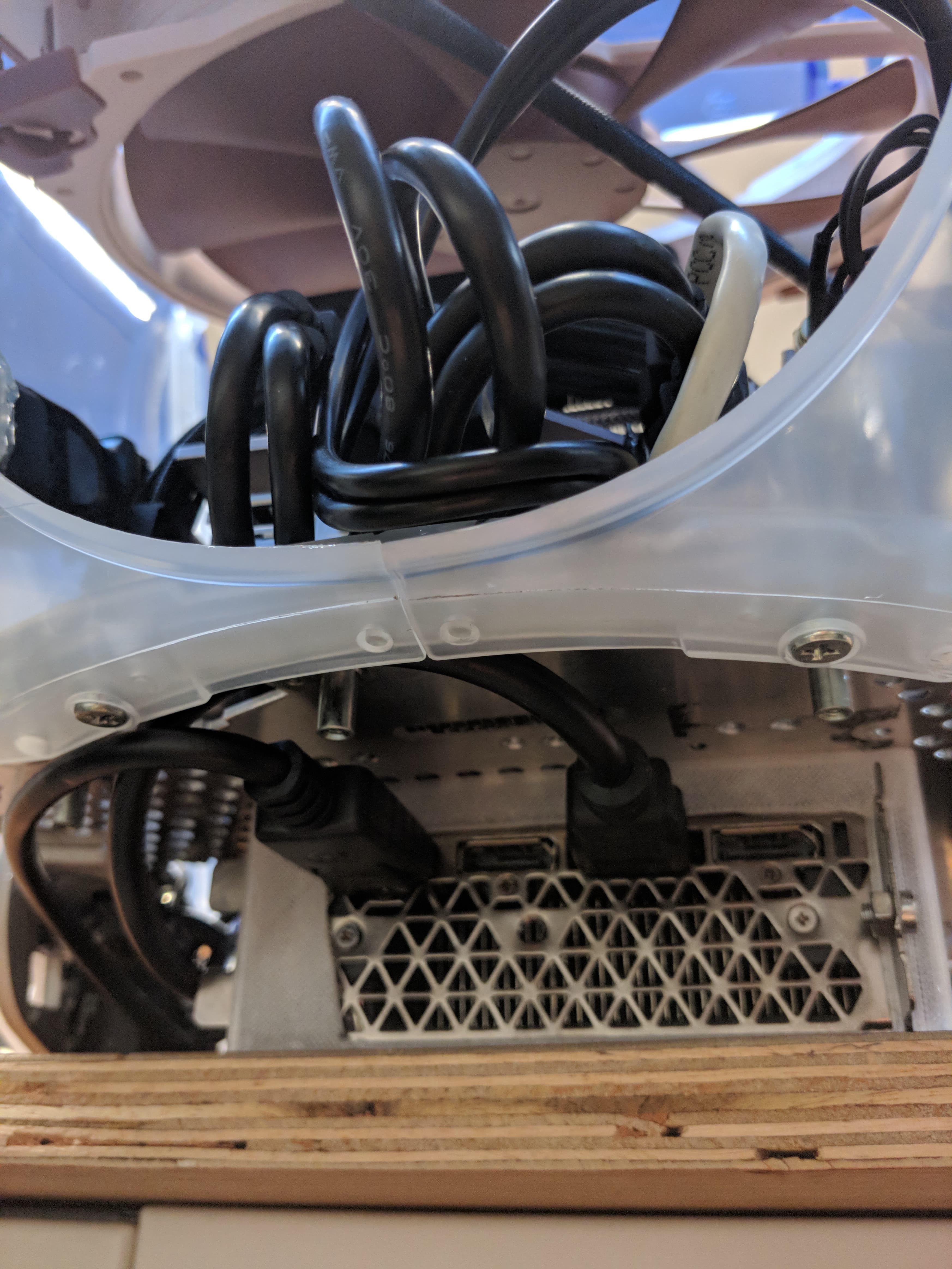
Time to call in some helping hands, this might be a little awkward on your own. Plug in the PSU cables, power for the monitor and your video cable. This was a very tight fit for me and required quite a bit of force to fit (which didn't feel good, I think I loosened the motherboard 24pin connector a little :s be careful!) After that's in place, screw in the 2 screws on top. Don't forget to wiggle in your power button and spring.
![]()
![]()
![]()
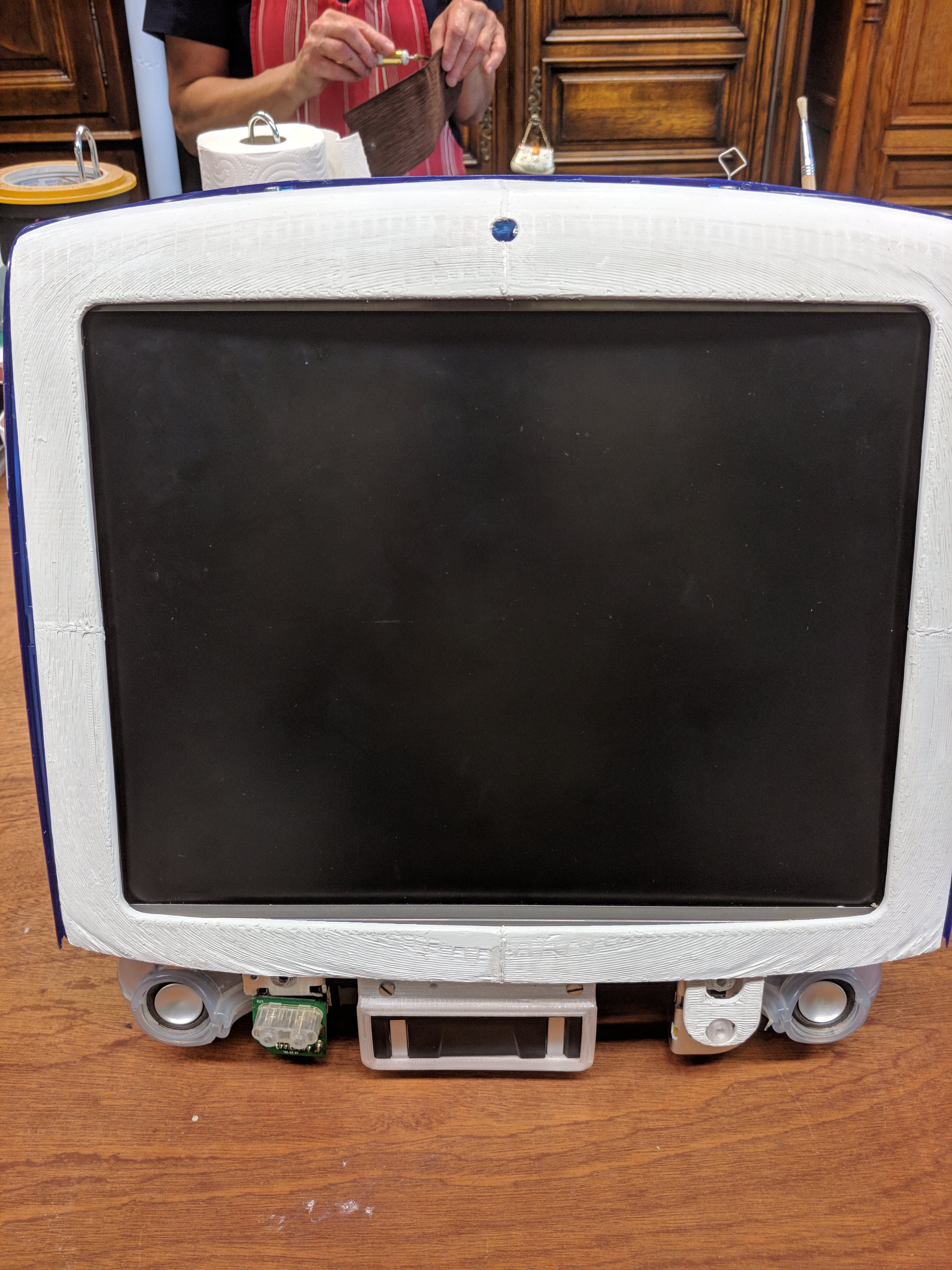
Put on the outer front bezel and lay this whole contraption down on the screen. Cross your fingers everything is screwed down in there
![]()
![]() Now fasten the front with some bolts, nuts and washers.
Now fasten the front with some bolts, nuts and washers. ![]()
You've gotten this far... Time to finish this. Put in your bottom fans (they don't require a 3d printed mount) and plug in the cable.
![]()
![]() Now put the bottom on there and screw in the bottom screws first (near the speakers)
Now put the bottom on there and screw in the bottom screws first (near the speakers) ![]() When those are secure, move on to the back and screw in the last two screws. You're done!
When those are secure, move on to the back and screw in the last two screws. You're done! ![]()
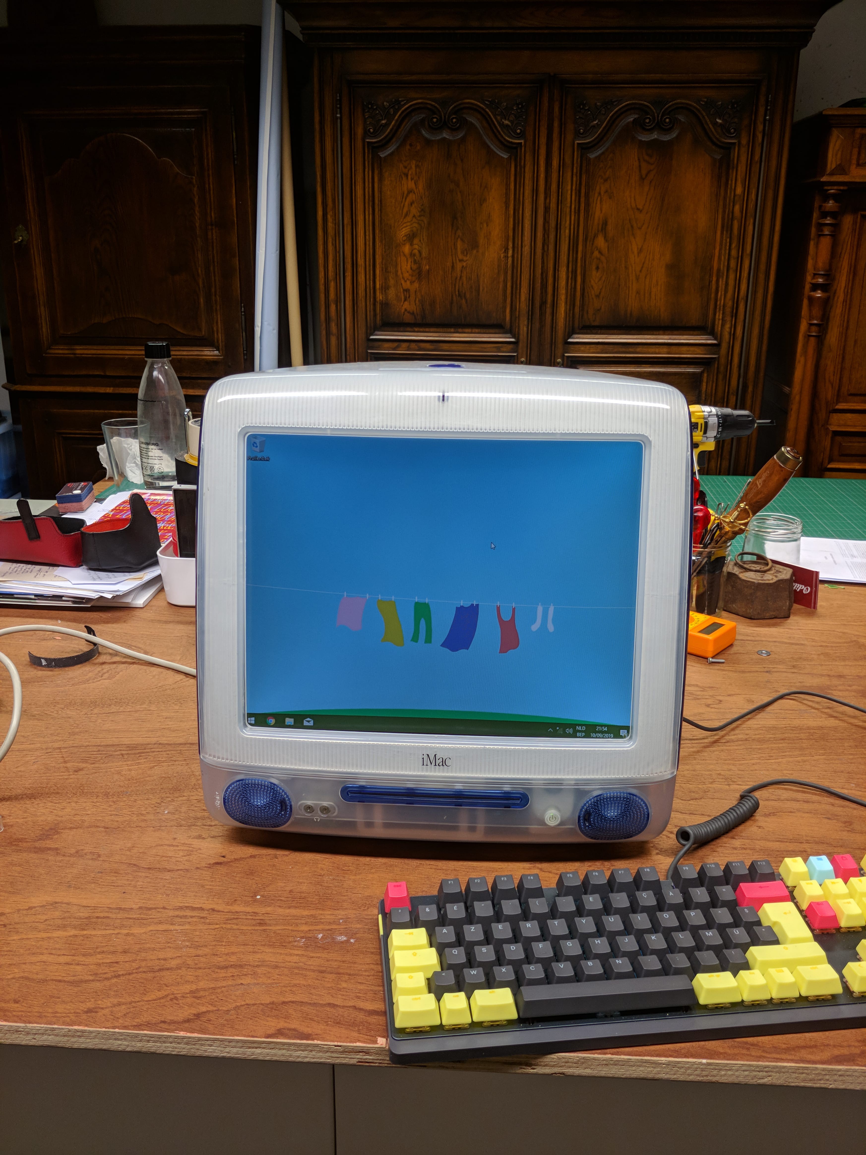
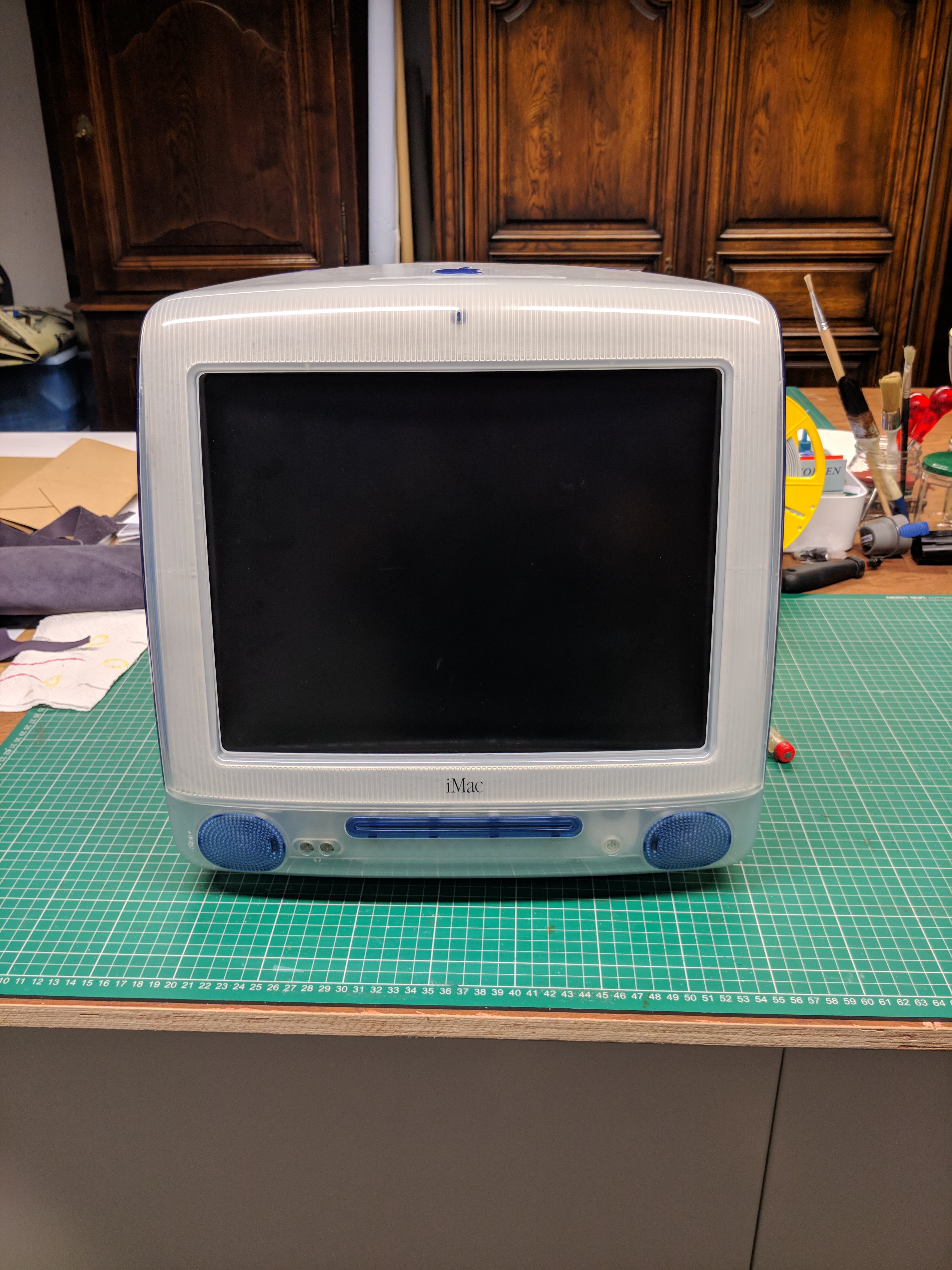
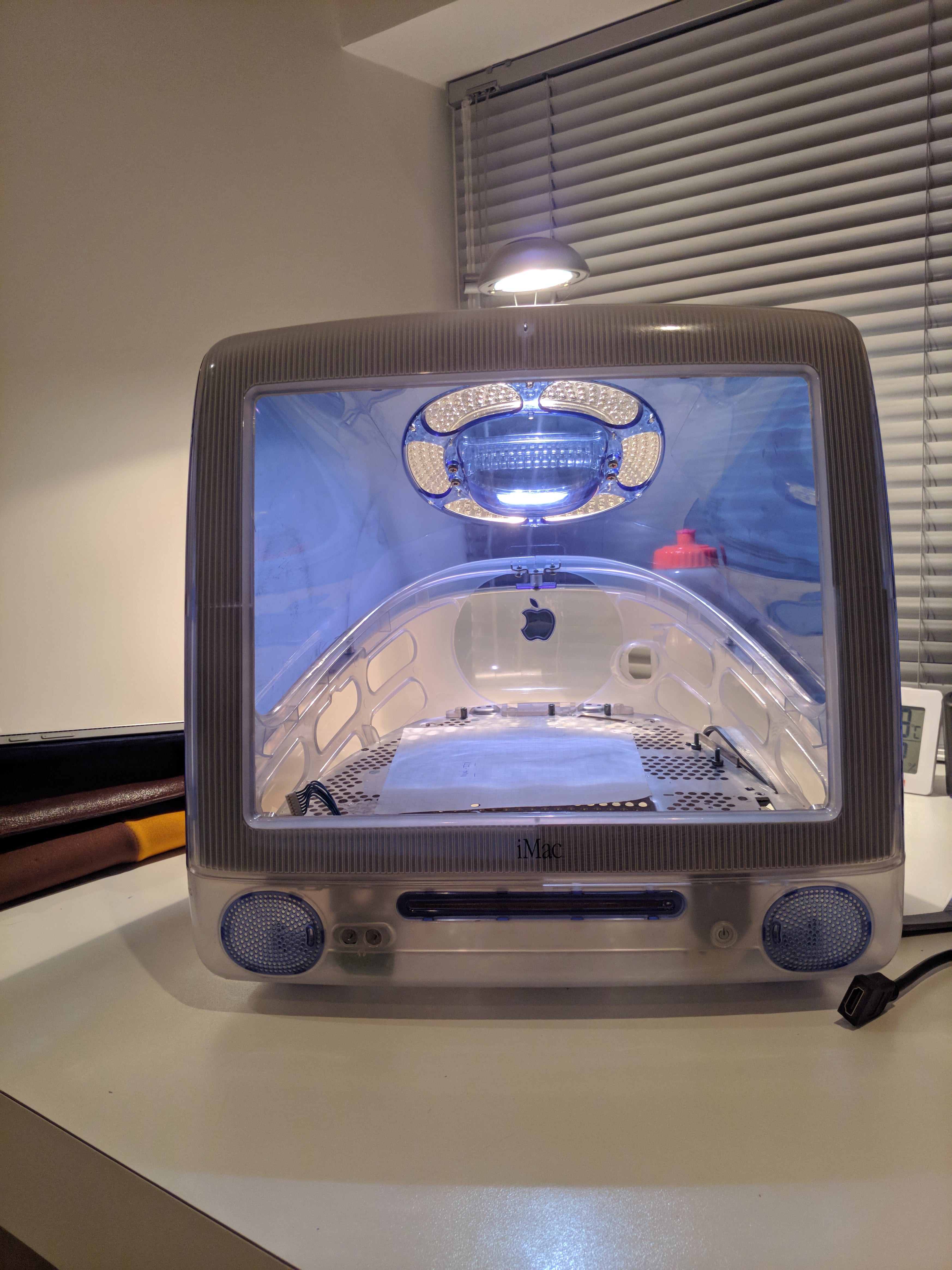
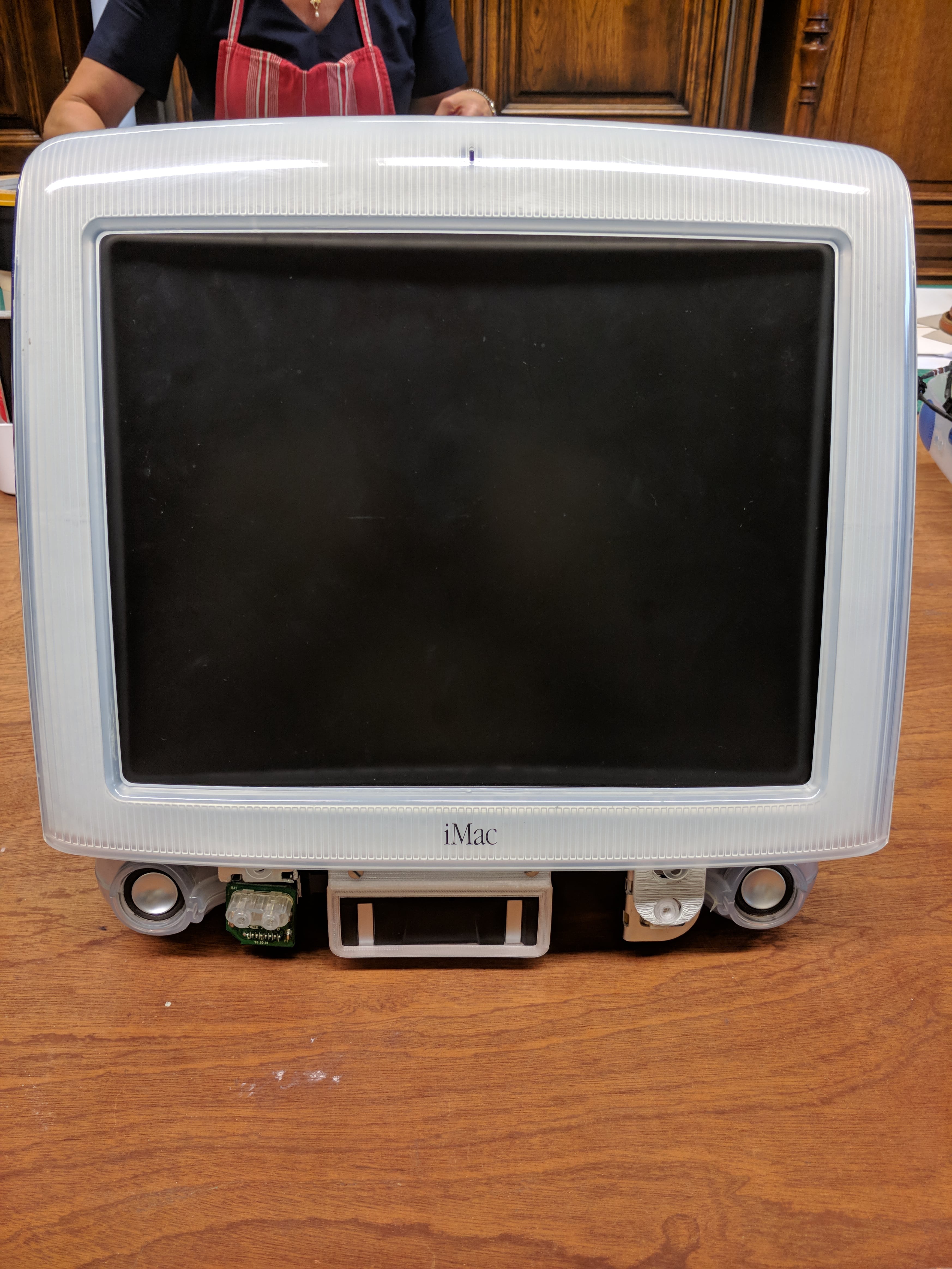
You did it! It's finally done! Now go enjoy your super customized pc :)
![]()
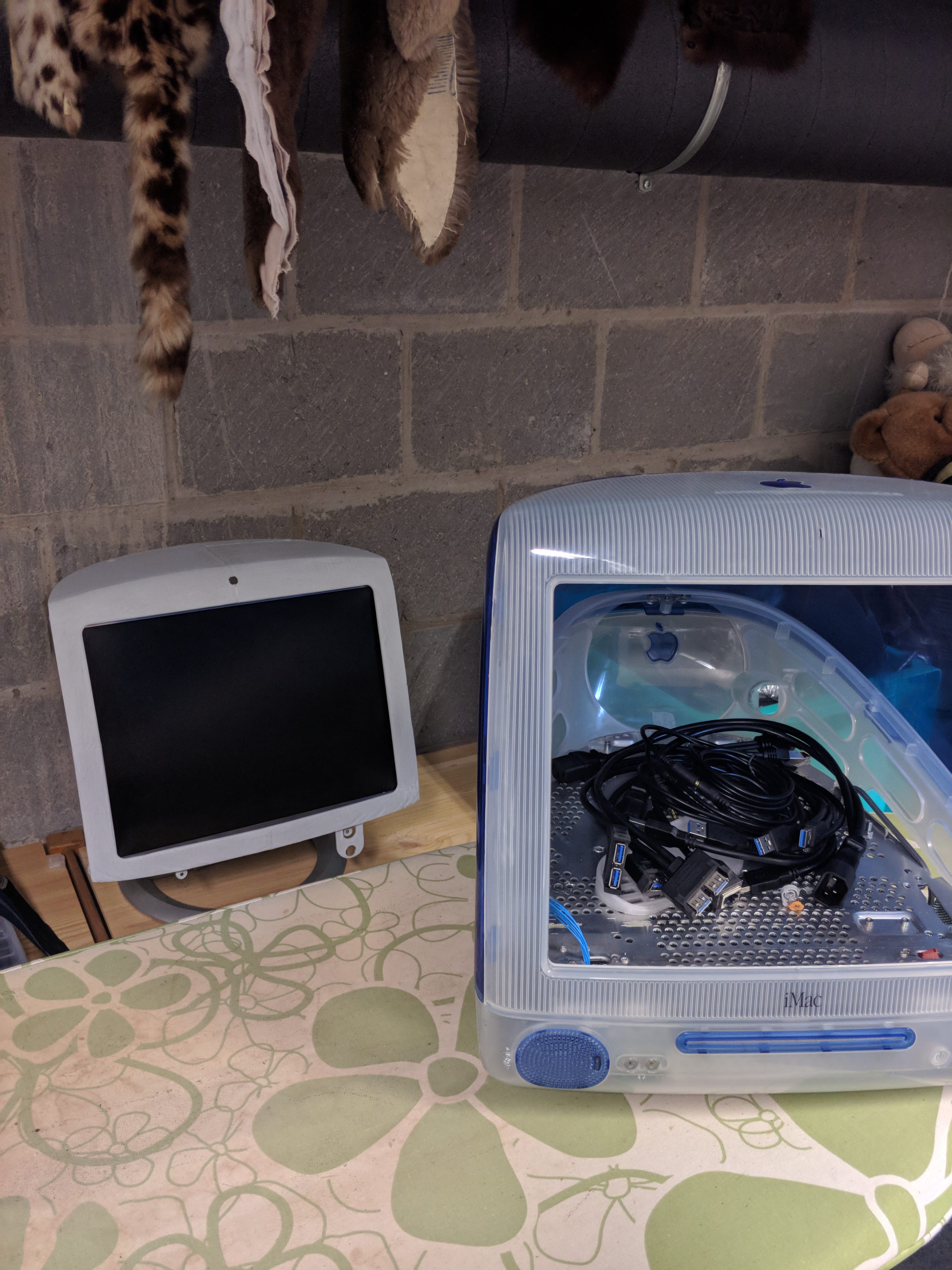
Here's the bad news... This thing gets hot, REALLY hot. Ventilation and airflow are definitely not its strong suit. With the parts I chose to put in there it was simply too hot and so... I had to take it all apart again. My harddrive was frying and the fans were whizzing full-speed non-stop. This wasn't a ̶v̶a̶c̶u̶u̶m̶ ̶c̶l̶e̶a̶n̶e̶r̶ computer I would use every day.
There might have been a way to fix these issues, like adding extra holes and fans, another place to mount the harddrive, but to me that would defeat the purpose because the mod would really take away from the original design. I always wanted this to look just like the original (or as close to it as possible).
![]()
This is my sad computer right now. It is certainly sad, but I'm happy that it isn't loud. Let this be a warning for someone who wants to do this, choose your parts wisely, maybe something very low power or a raspberry pi is better suited for this than a high end gaming pc.
In the end I'm happy I did this build because it taught me a lot about 3d modeling. It's been in the back of my mind since I was 12 and it makes me really happy that I actually made it real. The problems that arose were things I had foreseen, but hoped wouldn't happen. That's just life I guess.
This won't be the end for this mod however. I'm planning on putting something else in the case (like a raspberry pi) so my efforts won't have been for nothing after all. Expect another project log sometime in the future.
- For some extra ventilation on top, I added holes in a concentric pattern to the bulbous thing on the inside of the handle.
-
(Bad?) Decisions
08/03/2019 at 20:15 • 0 commentsI'm in the middle of my exams at uni right now and all I can think about is this computer, so I went home and worked on that instead of studying... bad decision...
However (!) after waisting just a single day I did fix the entire bezel :D
So here's a step by step:
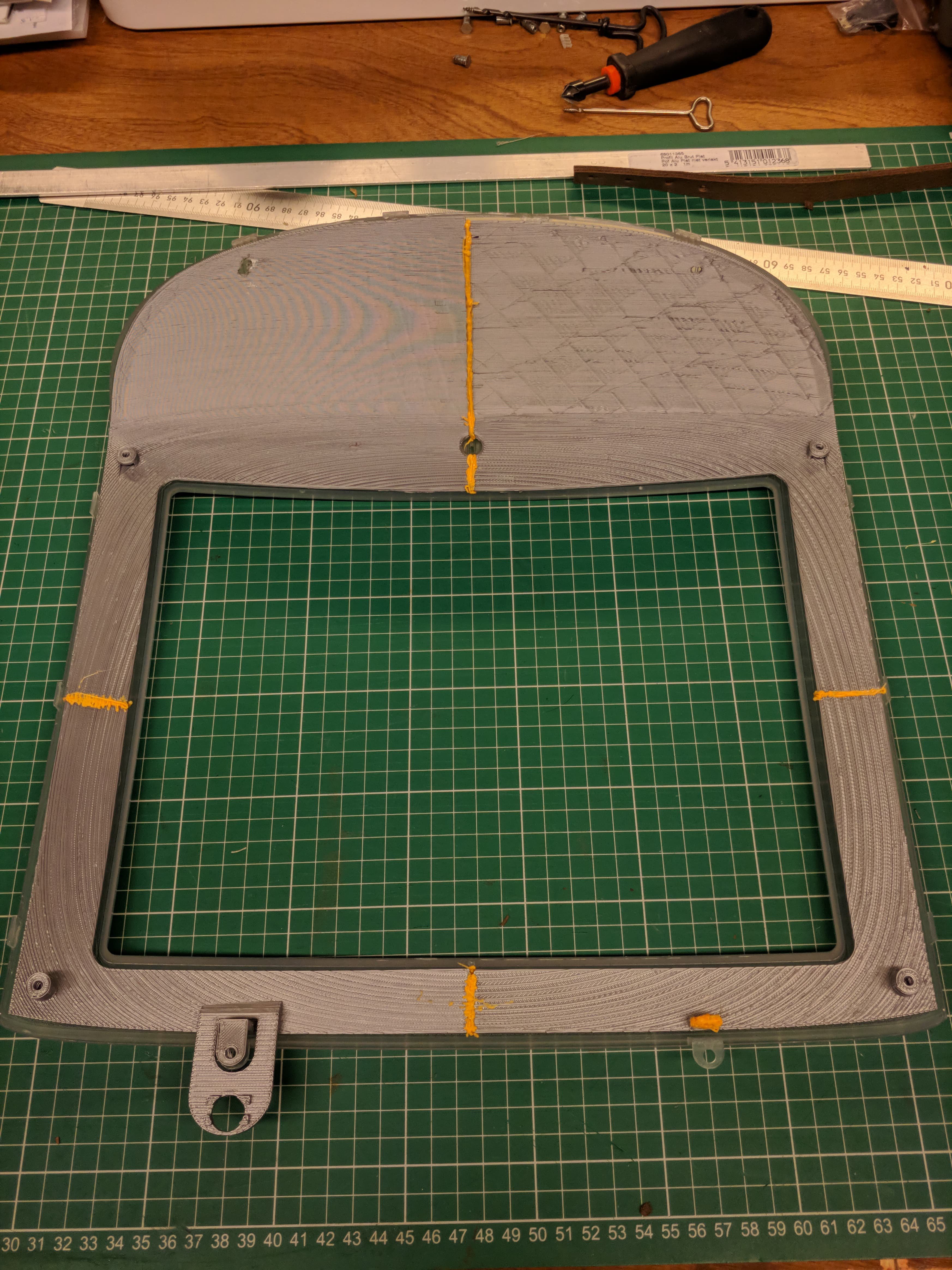
- Print all the parts for the bezel. I did mine at 0.2mm layer height and 100% infill. I've waisted enough plastic and I won't have this thing break on me :p (although that's still very much a possibility)
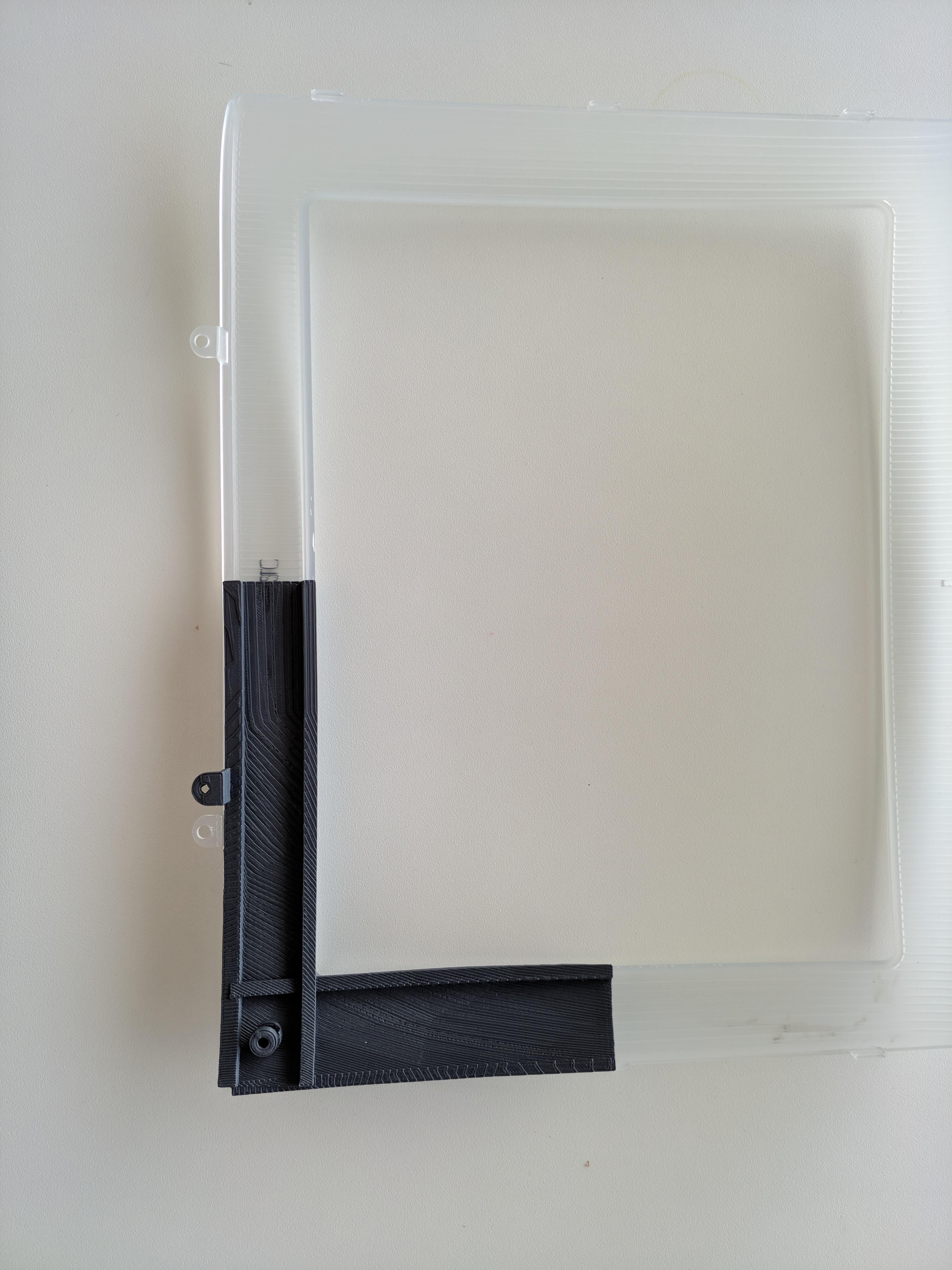
- Insert M4 nuts into the slots on each corner by melting them in with a soldering iron. Just put the nut as well as possible in the hole and heat it up with the soldering iron until it slides in. When it's in as far is it will go, put the LCD bracket on top and screw it in. Be careful not to push the nut deeper in or it could get stuck at an angle. Screwing the bracket in place while the nut is still warm will make sure that the plastic around it will still fit for the bracket.
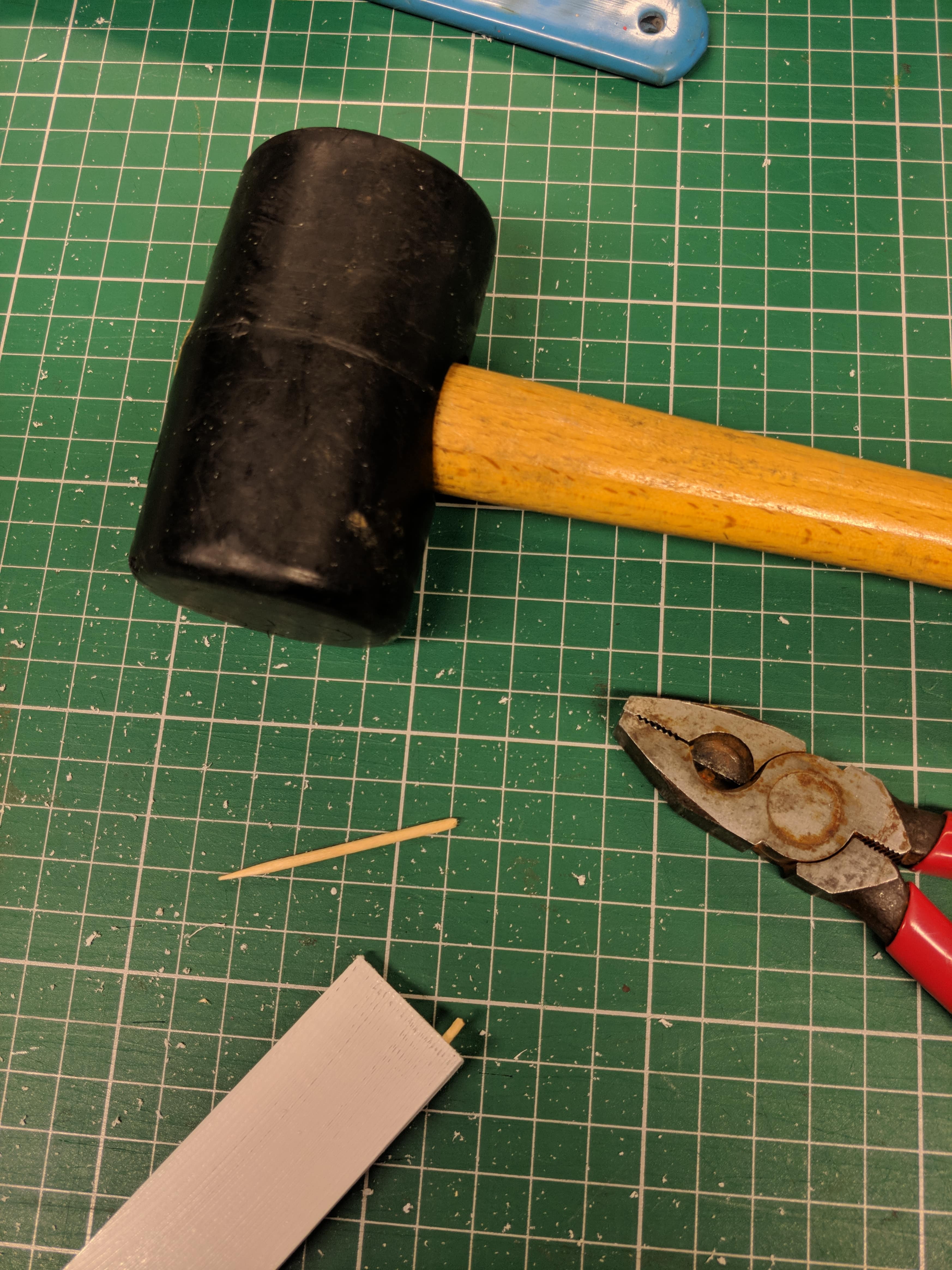
- Get some toothpicks and cut the tapering end off. Try and twist it into one of the holes on your parts. When you think it's in all the way, cut off the other end to about the same length.
![]()
- Then take it out and twist it into the same hole with the other end, being careful not to break it in half. If it won't go in all the way, no problem, just use a hammer to tap it in gently.
![]()
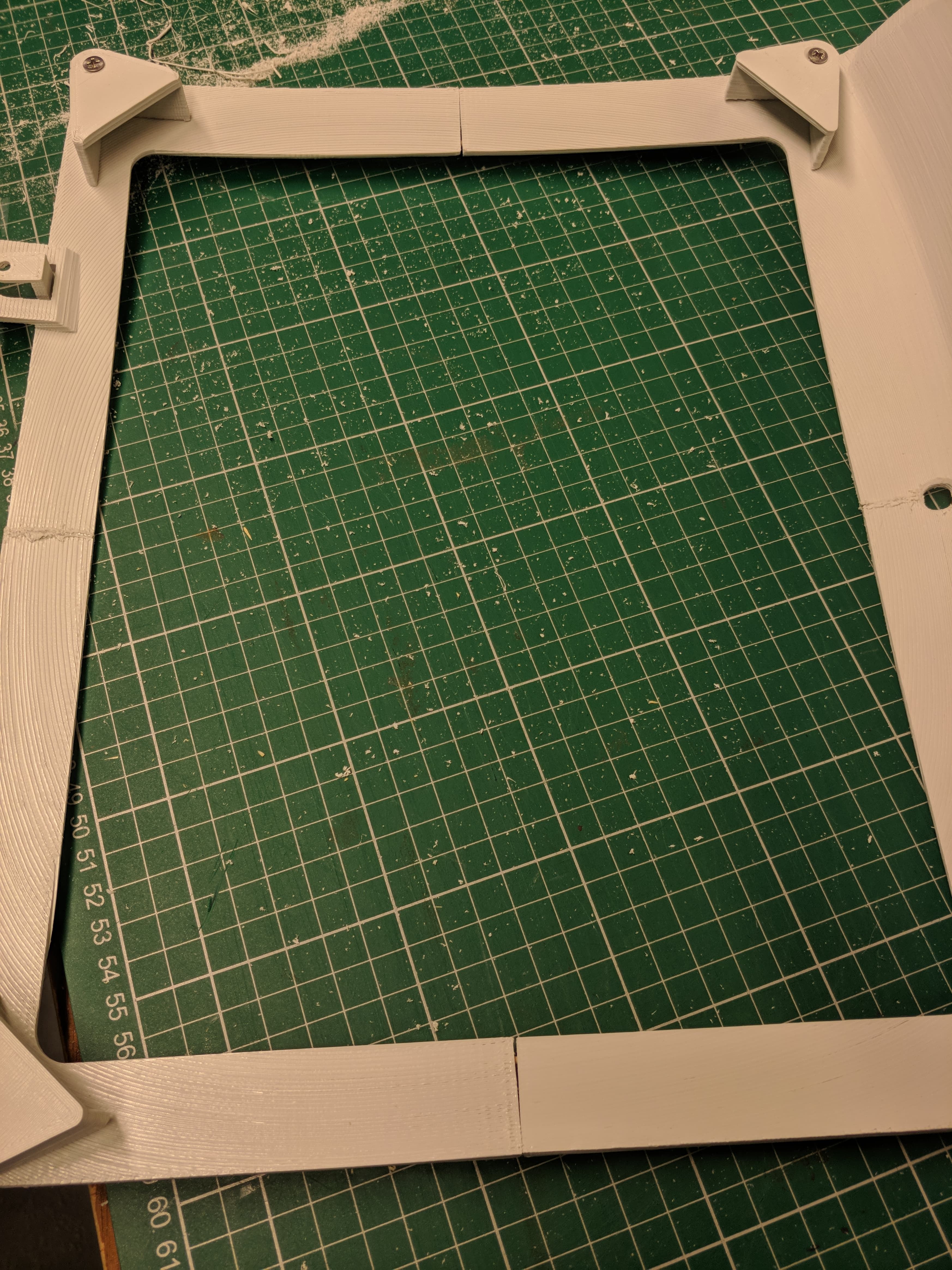
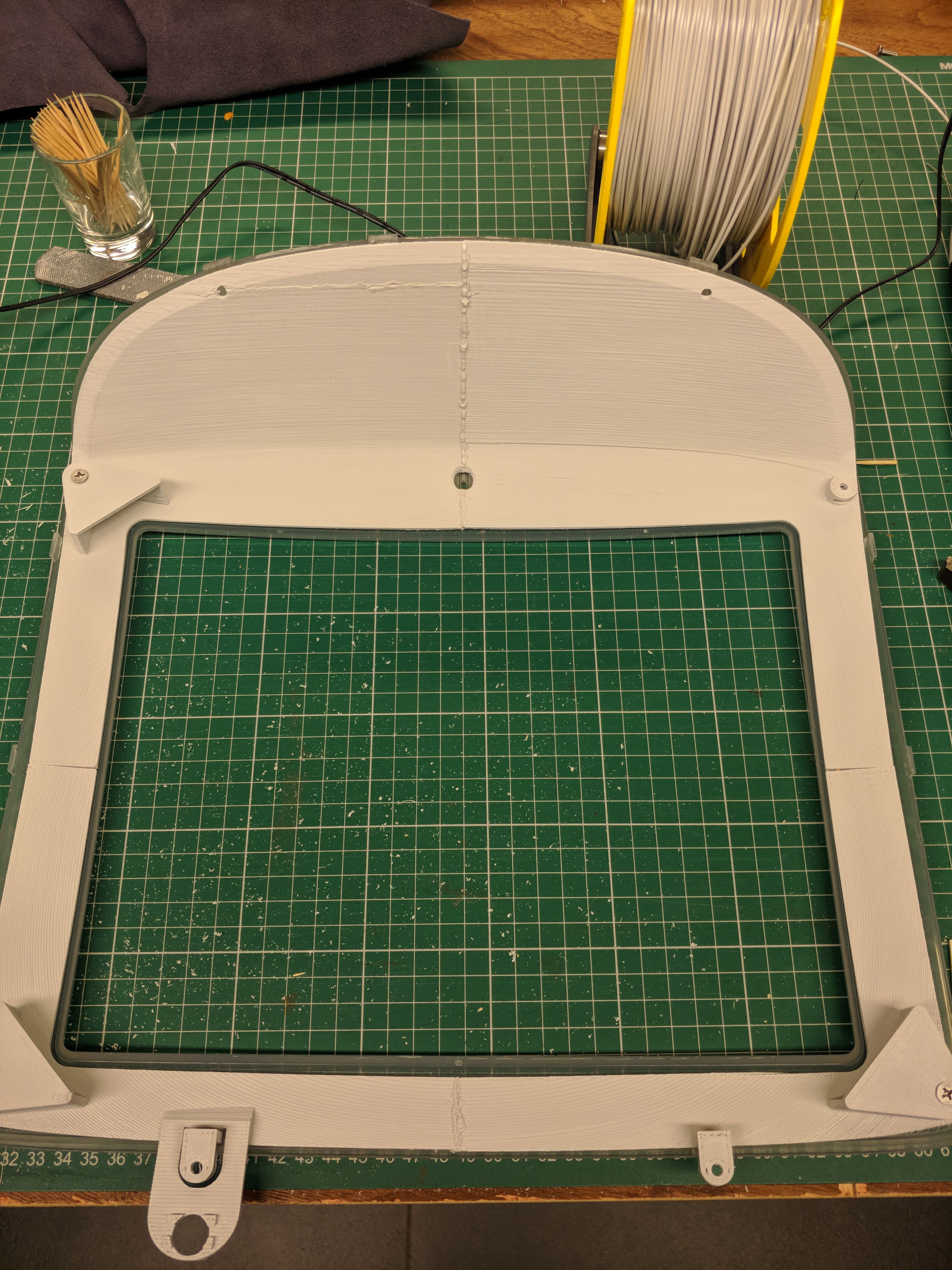
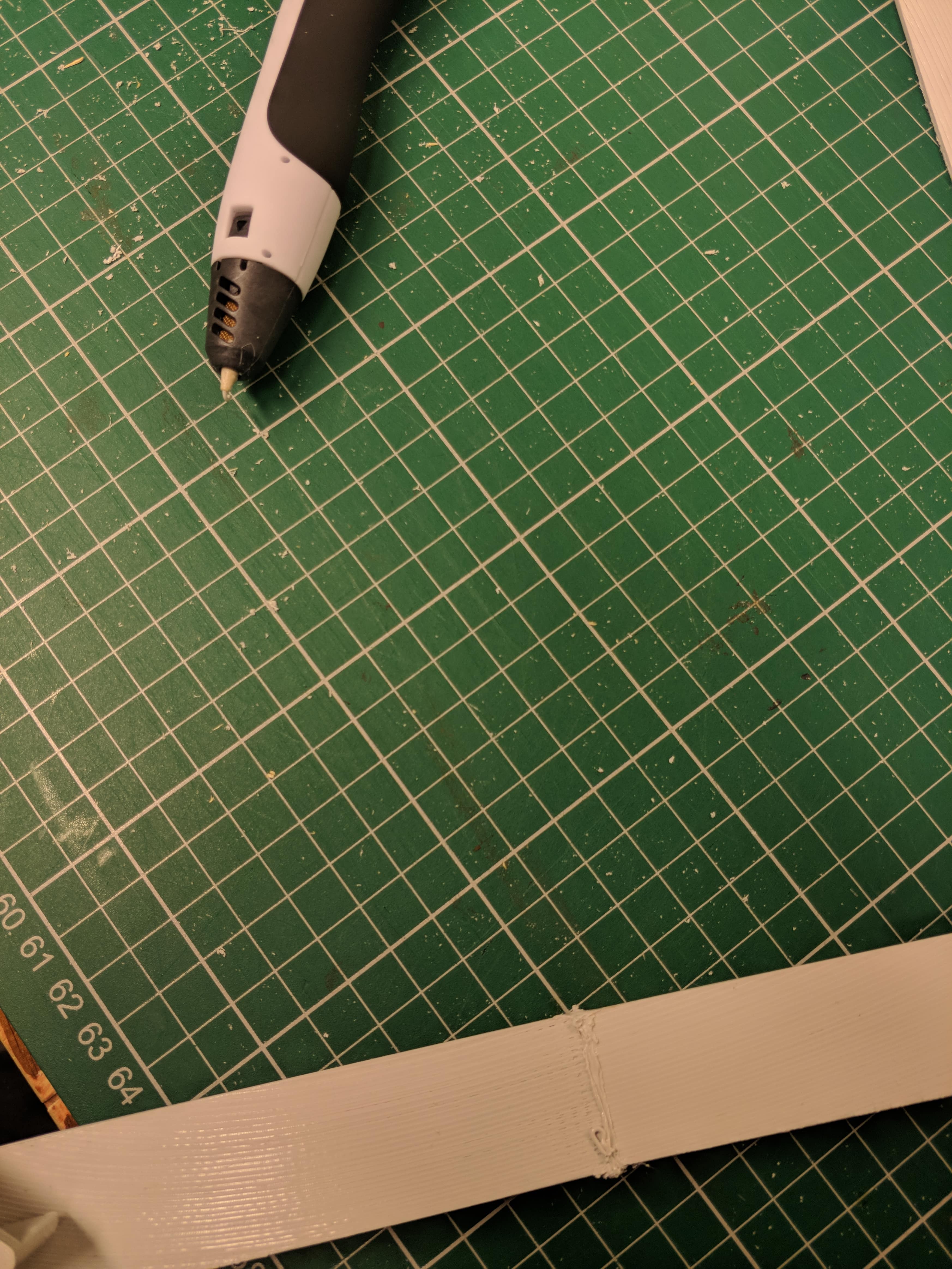
- When all the holes are filled on one side, combine your parts and use your 3d pen to weld them together. Be sure to fit it in the outer bezel every step of the way to make sure it always fits, using a file to adjust when needed.
![]()
![]()
![]()
Once you've done this for all 4 parts, your bezel should be complete. Try if your LCD fits and bask in the feeling that this project is almost over.
I think it's beautiful, but this might be a 'my baby' kind of situation.
![]()
![]()
-
I'm a welder now
07/29/2019 at 12:13 • 0 commentsSo I bought a 3D pen to try and weld the 4 bezel parts together.
This is the test run on some prototype prints. I'm amazed by how easy this was and how sturdy the result actually is.
![]()
Final result (bezel only) will be ready in a week :D
-
iMac Connectome
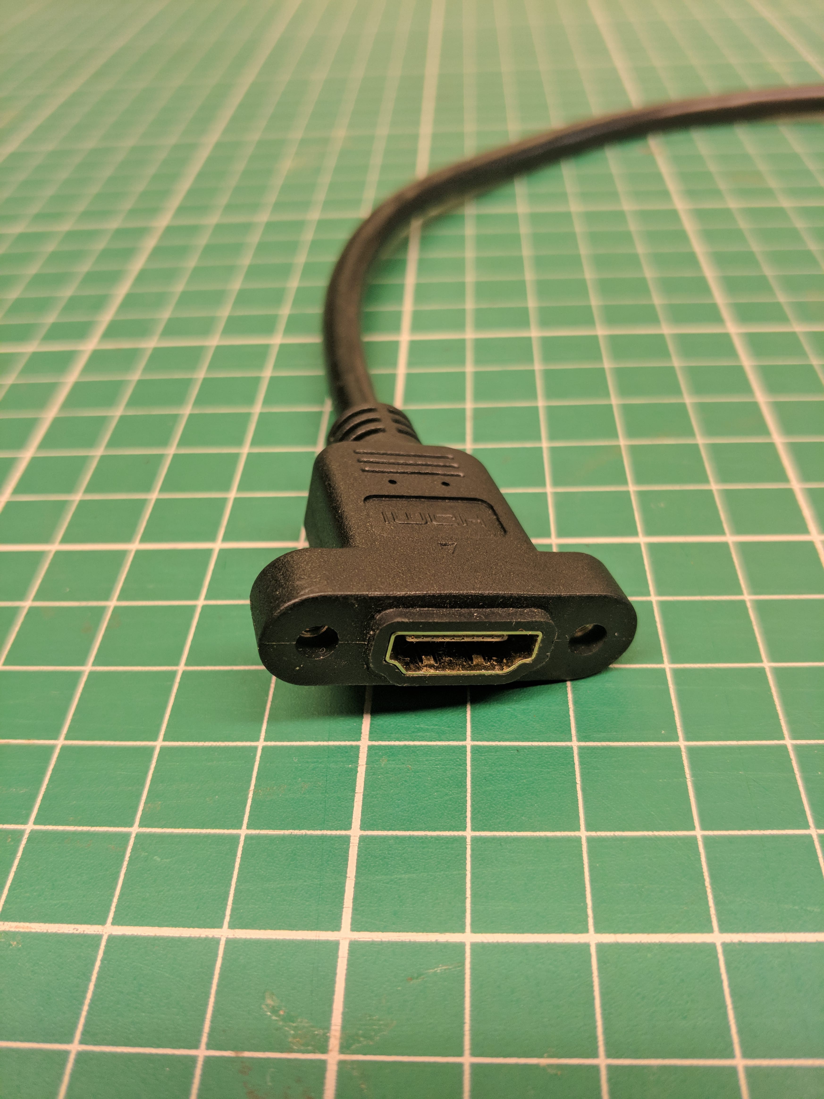
07/24/2019 at 13:58 • 0 commentsSome of the extension cables for the IO shield arrived, so I'm trying to finish the layout and print a final version.
A few of these cables have screw holes and extra protection that's going to be in the way, so I'm removing that with a box cutter.
![]()
![]()
I tried some test prints with the transparent PETG filament I bought some time ago and got pretty good transparency, but the geometry of the IO shield doesn't seem to work as well. Might need to work on that if I really want it to be more transparent.
![]()
All in all I think it's coming along quite nicely.
![]()
I'll be doing a few things next:
- Printing a final IO shield (more transparent)
- Using epoxy to glue the cables to the IO shield
- Printing the front bezel in a final plastic and using a 3d pen to weld the (glued) parts together
After all that is done, I can focus on mounting the internals.
-
Mounting them holes
07/05/2019 at 14:53 • 0 commentsMy PSU hasn't arrived yet, but I plan to put it underneath the metal baseplate of this iMac.
Problem: There isn't really enough space in terms of height.
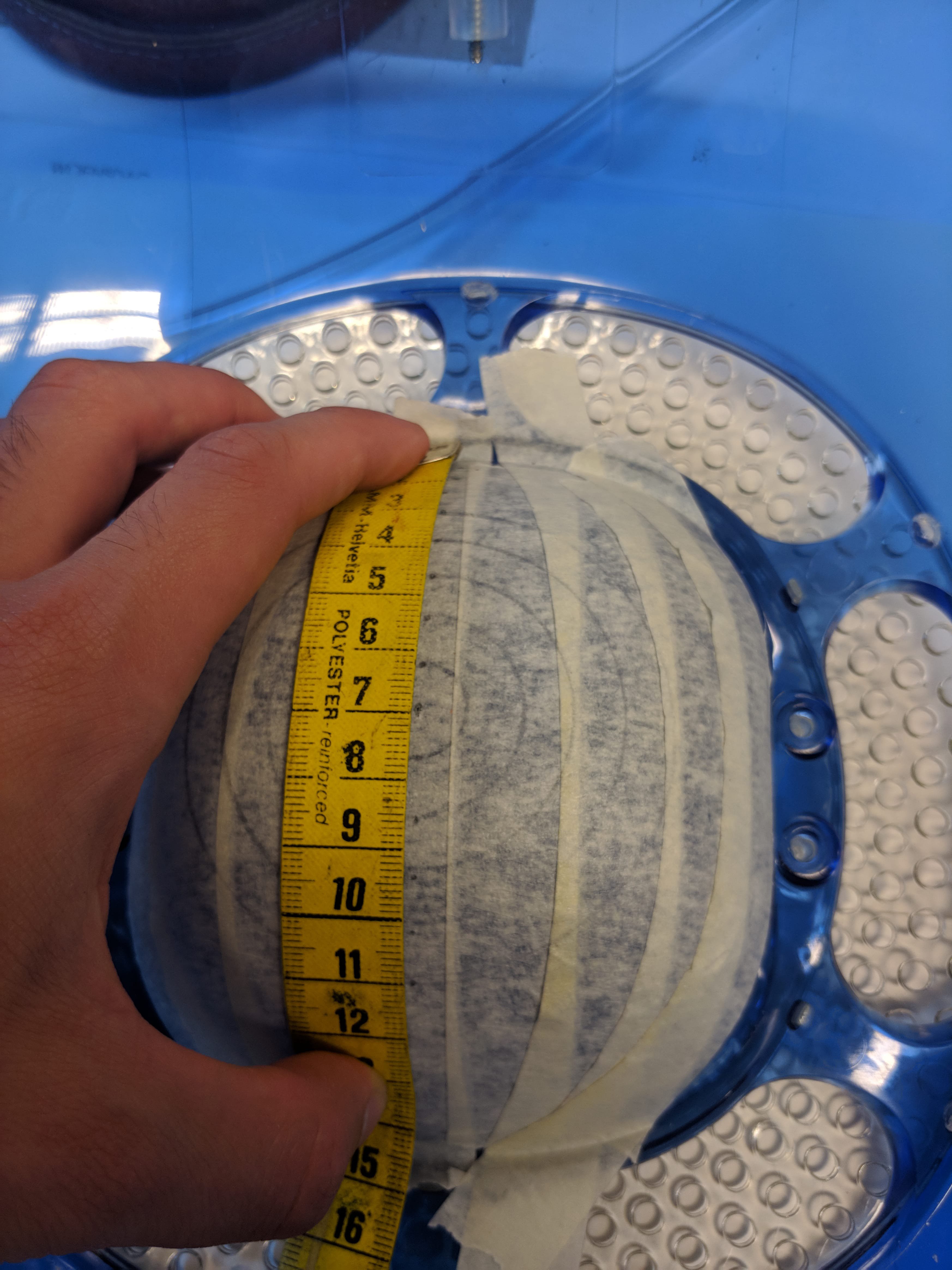
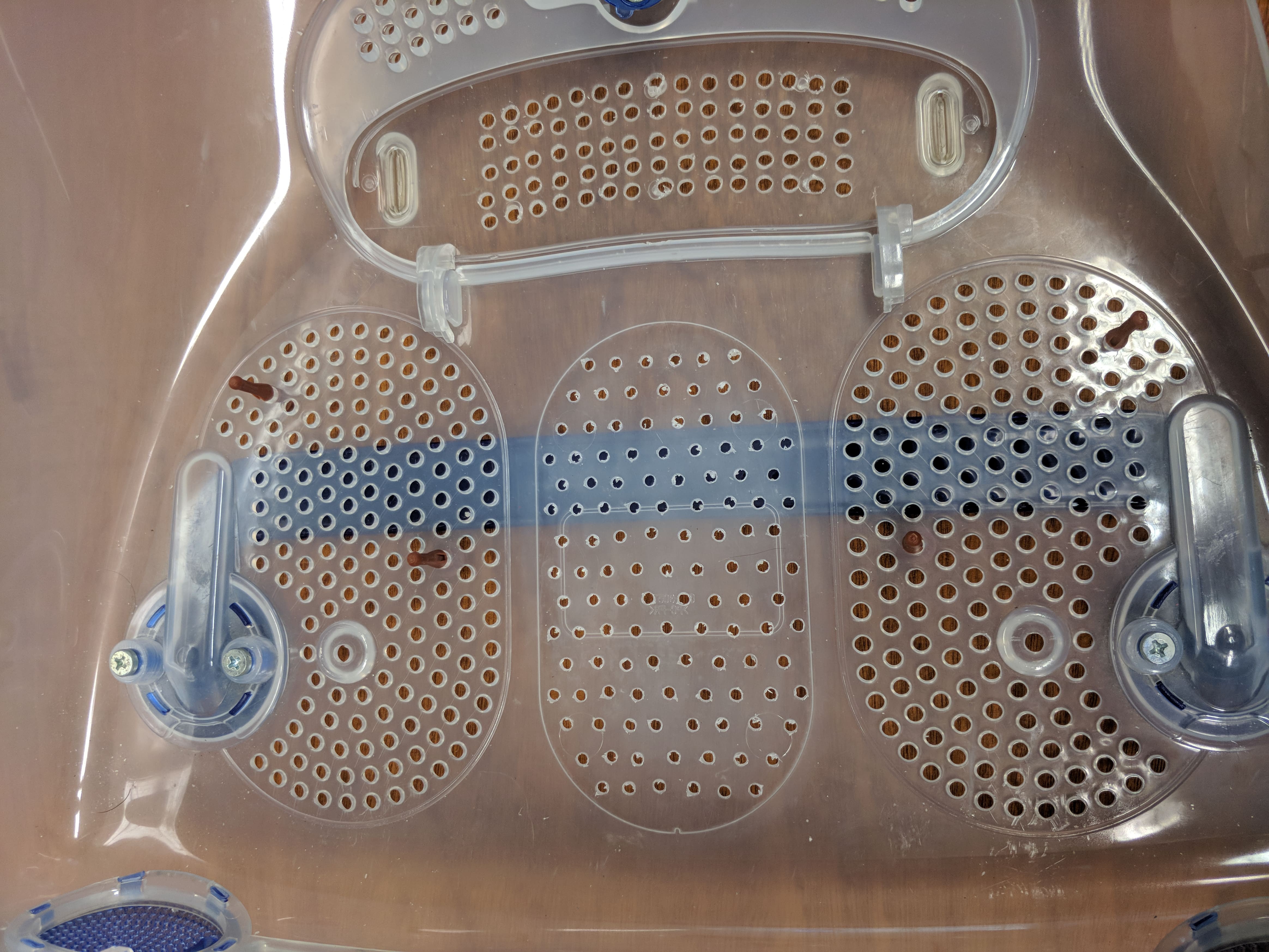
Solution: Permanently glue the RAM access flap in place and add some holes for extra ventilation.
The holes are spaced 7mm apart and are about 4mm diameter. Mine are certainly not perfect, but they're also not that bad.
![]()
![]()
*** Update this with pictures of permanently glued plate ***
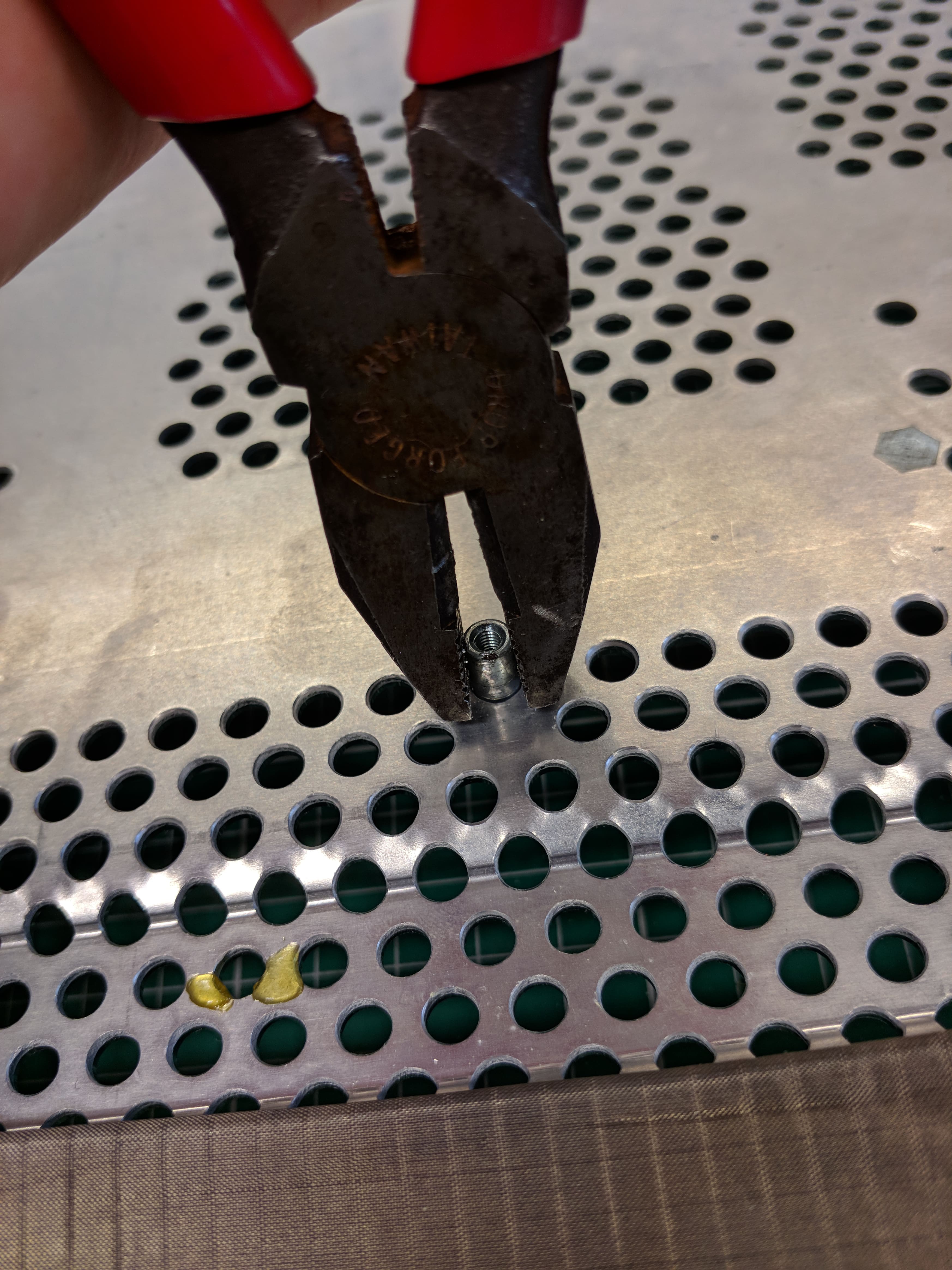
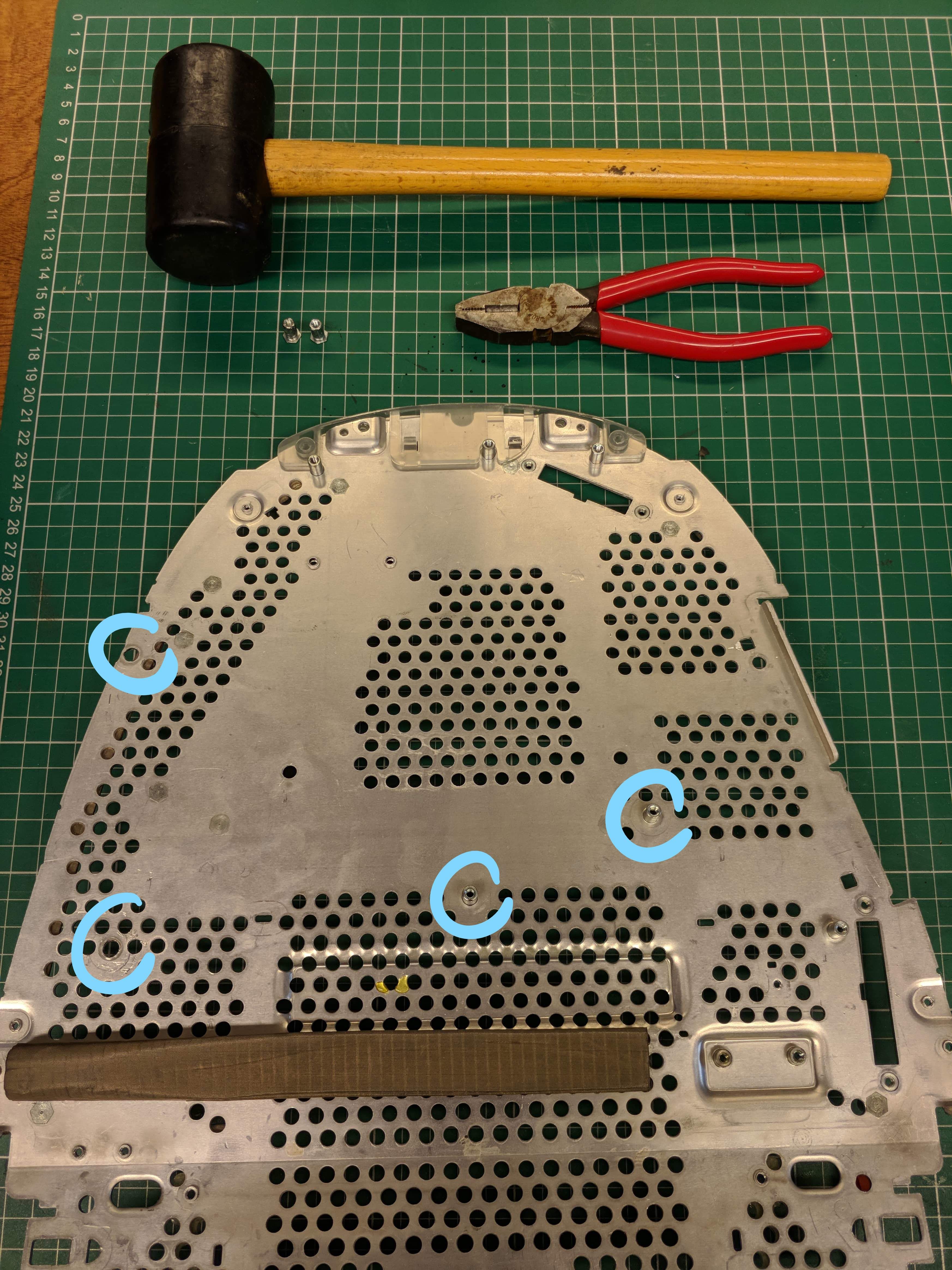
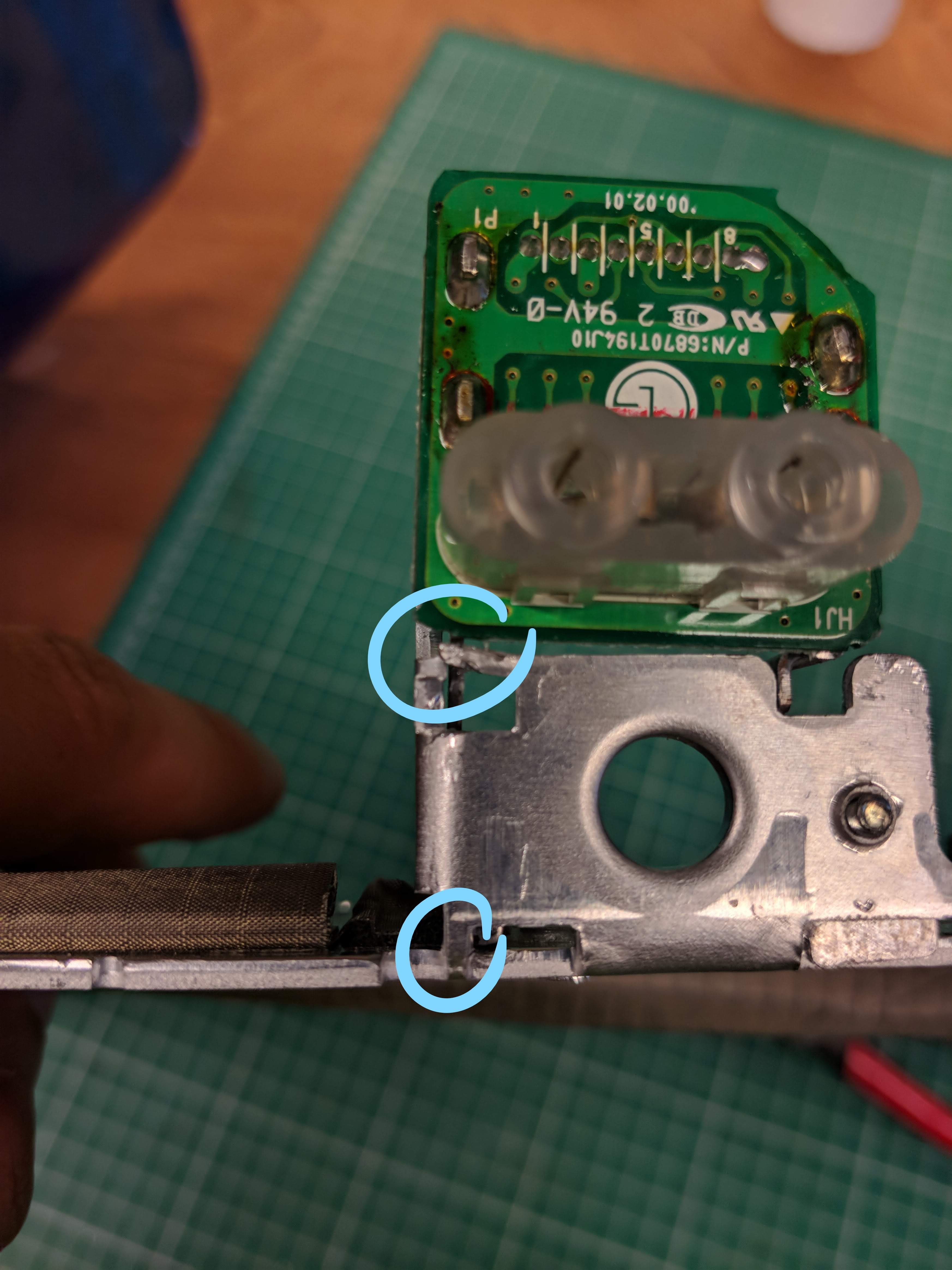
I also wanted to remove some of the standoffs that are on the metal plate, because they might be in the way of my motherboard . I read online on this guy's mod of the G3 that you can just wiggle them off. After some vigorous wiggling and smashing with a hammer I got the hang of it.
![]()
![]()
Just be careful with your hammer, don't go too crazy or you might break something...
![]()
I also finally finished the mounting plate for the IO shield. Took my a couple tries, but got there eventually.
![]()
![]()
-
Show me those curves ;)
06/07/2019 at 15:47 • 0 commentsAfter printing about 7 failed attempts, I got tired of wasting plastic and remembered I had a 3D scan laying around. This helped A LOT!
The model now fits and I'm finishing it off with a power button mount and some brackets for the LCD. Fingers crossed this whole contraption is strong enough to support the weight of my LCD.
In the meantime I've also been working on the IO shield. Had the same problem, this iMacs curves are just too pretty to be modeled by a novice like me. Made a scan here too and now it fits perfectly. (no really, almost better than the original)
I'll check back in when the model is finished and I can start glueing this thing together.
-
Recreating old parts
04/09/2019 at 19:06 • 0 commentsAfter paying reddit user u/dahmze1 to make me a model of the inner bezel, I tried to print it. Sadly it didn't fit at all, so I've started modeling it from scratch again.
![]()
![]()
Lucky for me my modeling skills have improved significantly and with a model to start off from I had a little better success.
![]()
After tuning in my printer, I printed the first attempt. Alas, didn't fit. But it's getting close...
![]()
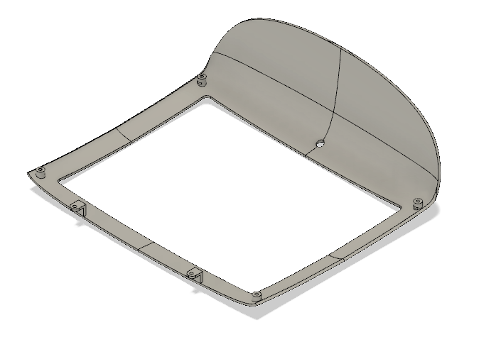
Clearly some tweaking is still needed.
 I tried measuring by hand, but that turned out to be a hasstle, so I made a template (like one on those strands of people holding hands you make as a kid) that would show me where to drill holes in a hexagonal pattern.
 The finished product should look something like this (this is with the arms for the 200mm fan attached).
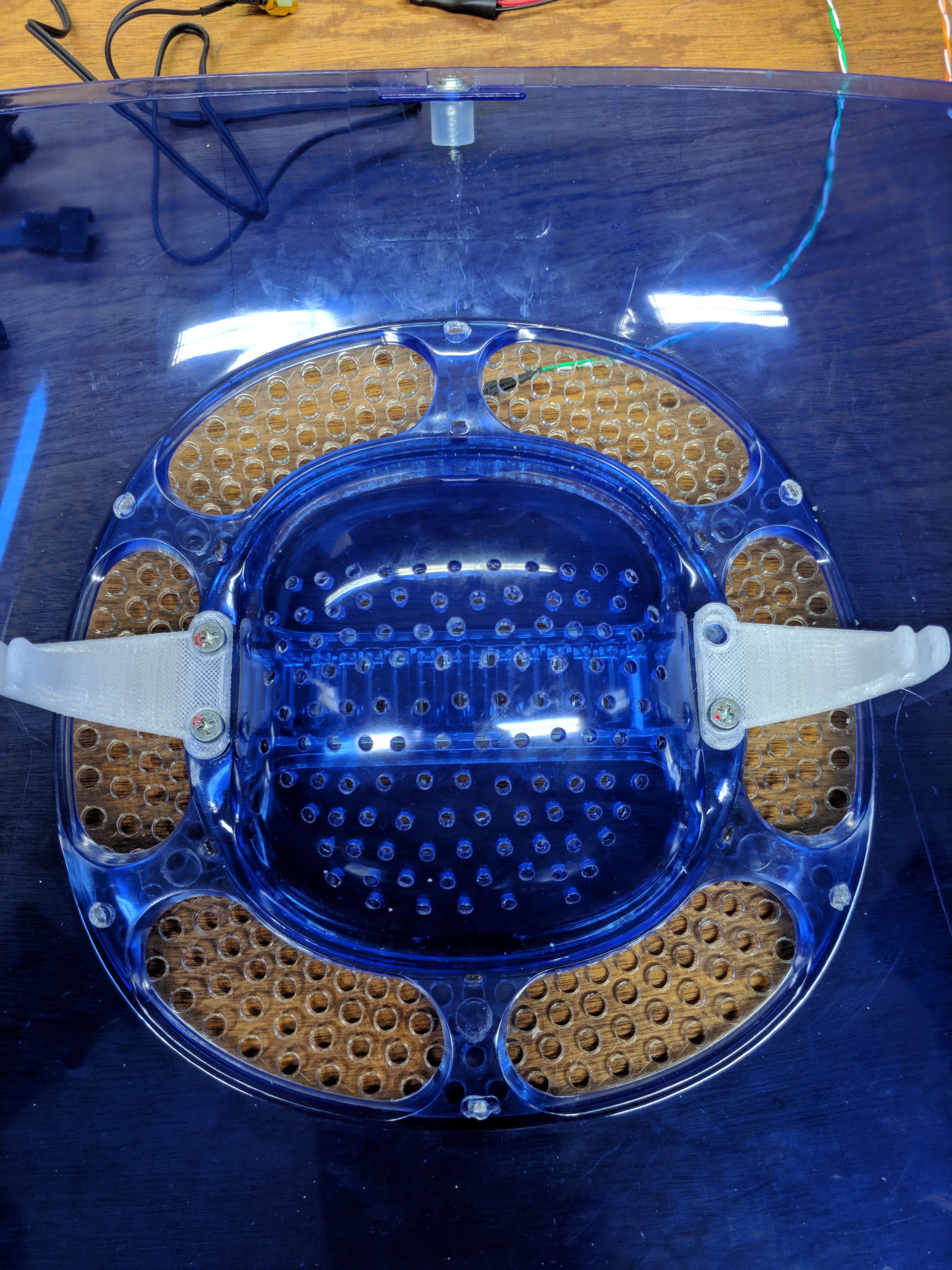
 The front (directed towards the back of the iMac) wasn't that bad. The back however...
 As you can see I used metal brackets on this one instead of 3d printed angles. That's because the PETG I was printing in kept breaking on that spot and this was on day 4 and I got tired of waiting for the printer. I might update the model (this is also a model with a part cut off and holes drilled into it)... or I might not... We'll see :P
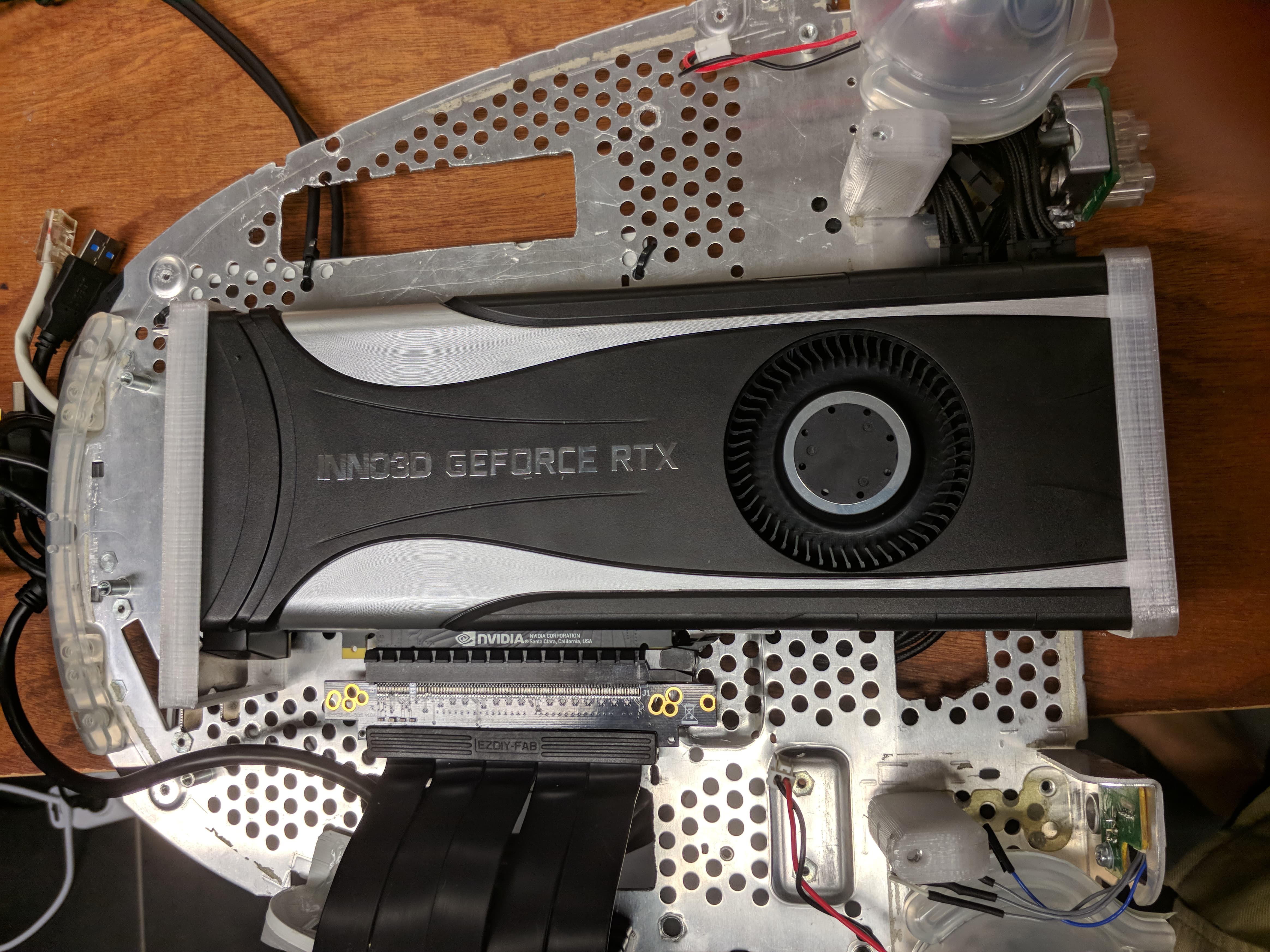 When adding in the GPU it's also important to have the power cable and PCIe extension already plugged in. It's so tight in there that I couldn't get to the connectors when it was screwed in.
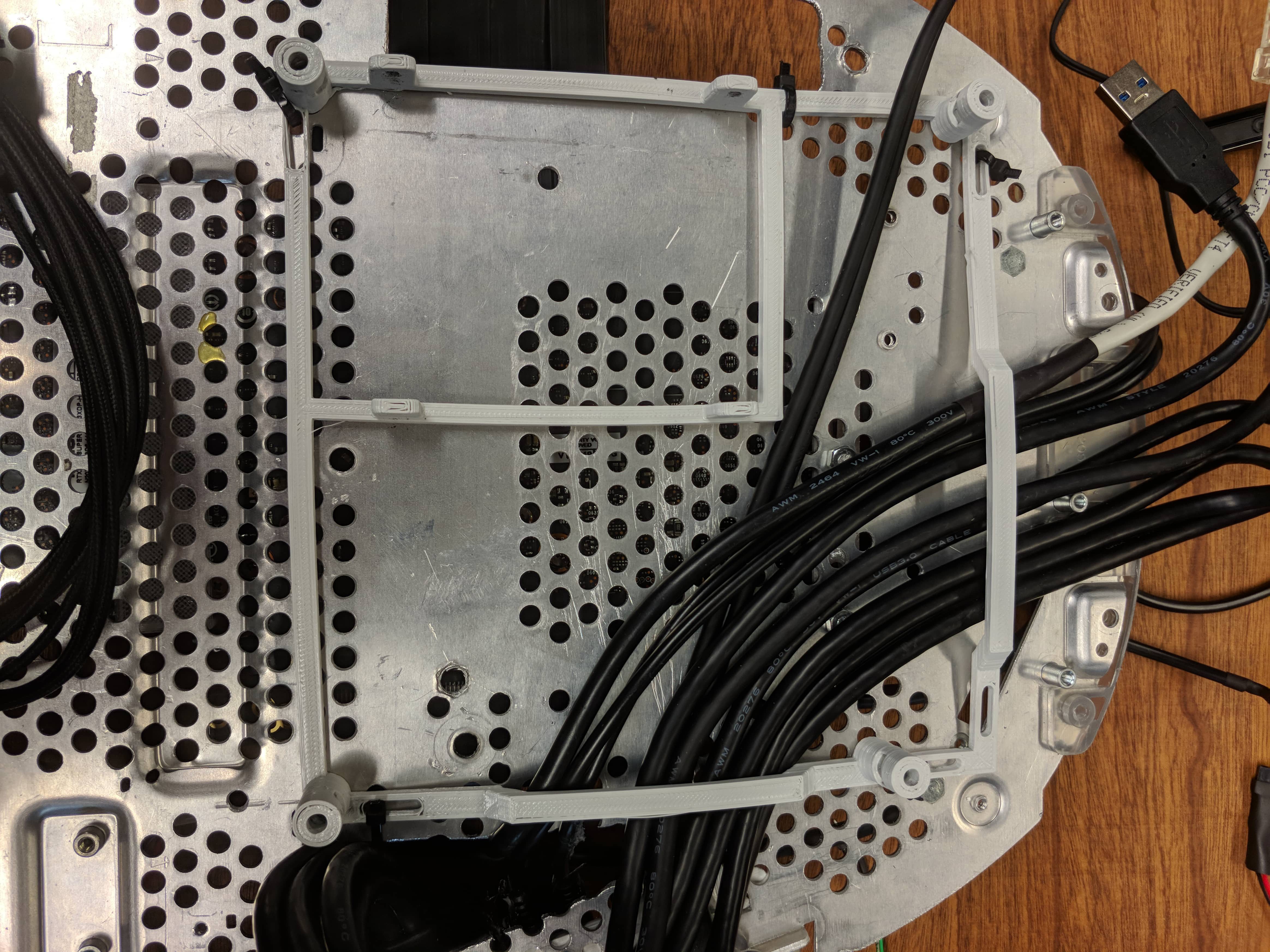
 If you have it, also add the wifi antenna.
 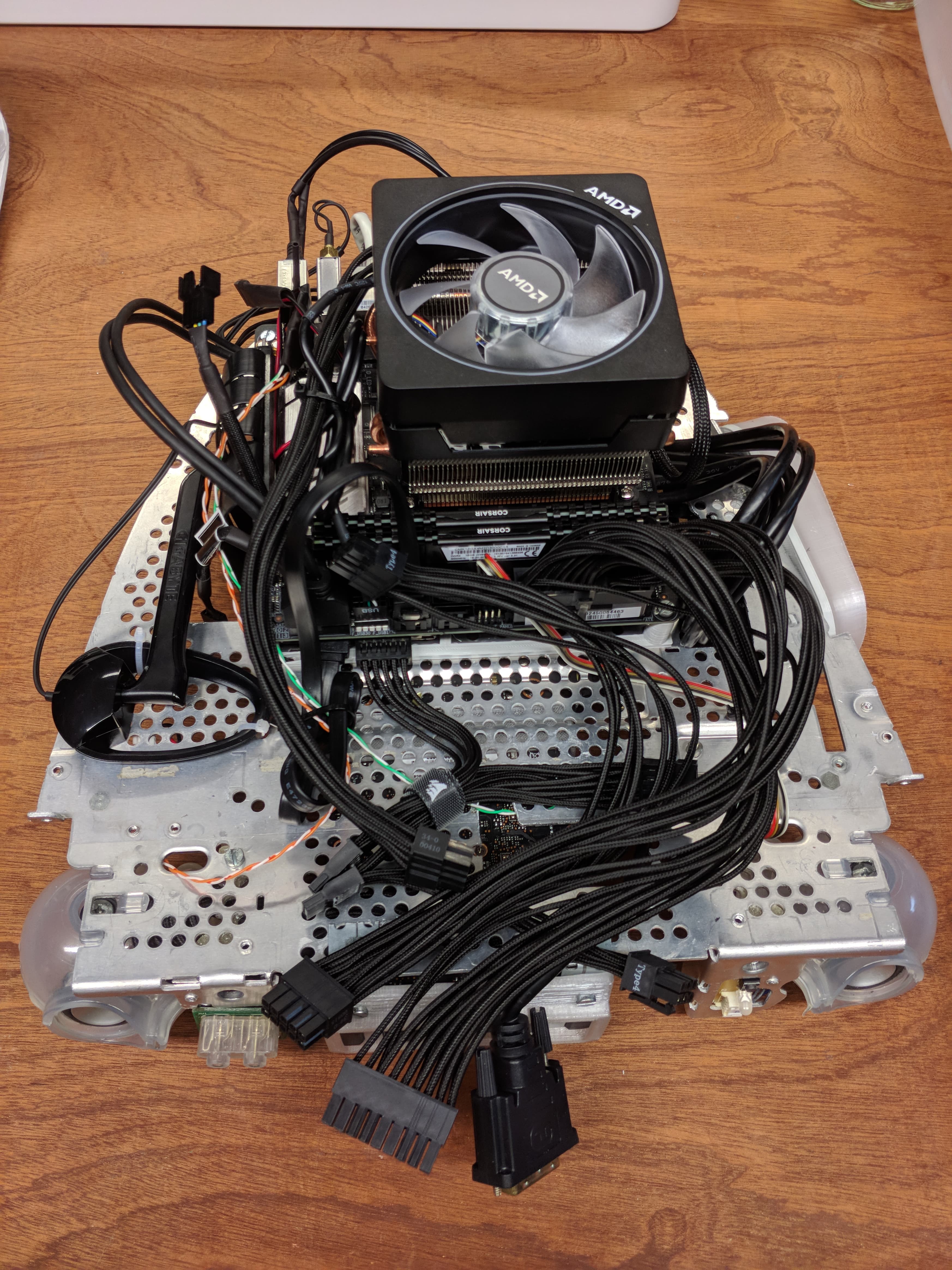 And then try and manage those cables as best you can. I promise it won't be easy ;)

 There's 4 screws to get here: 2 on the front
  and 2 on the back.
  It should just pop into place with those 2 tiny plastic alignment bumps.
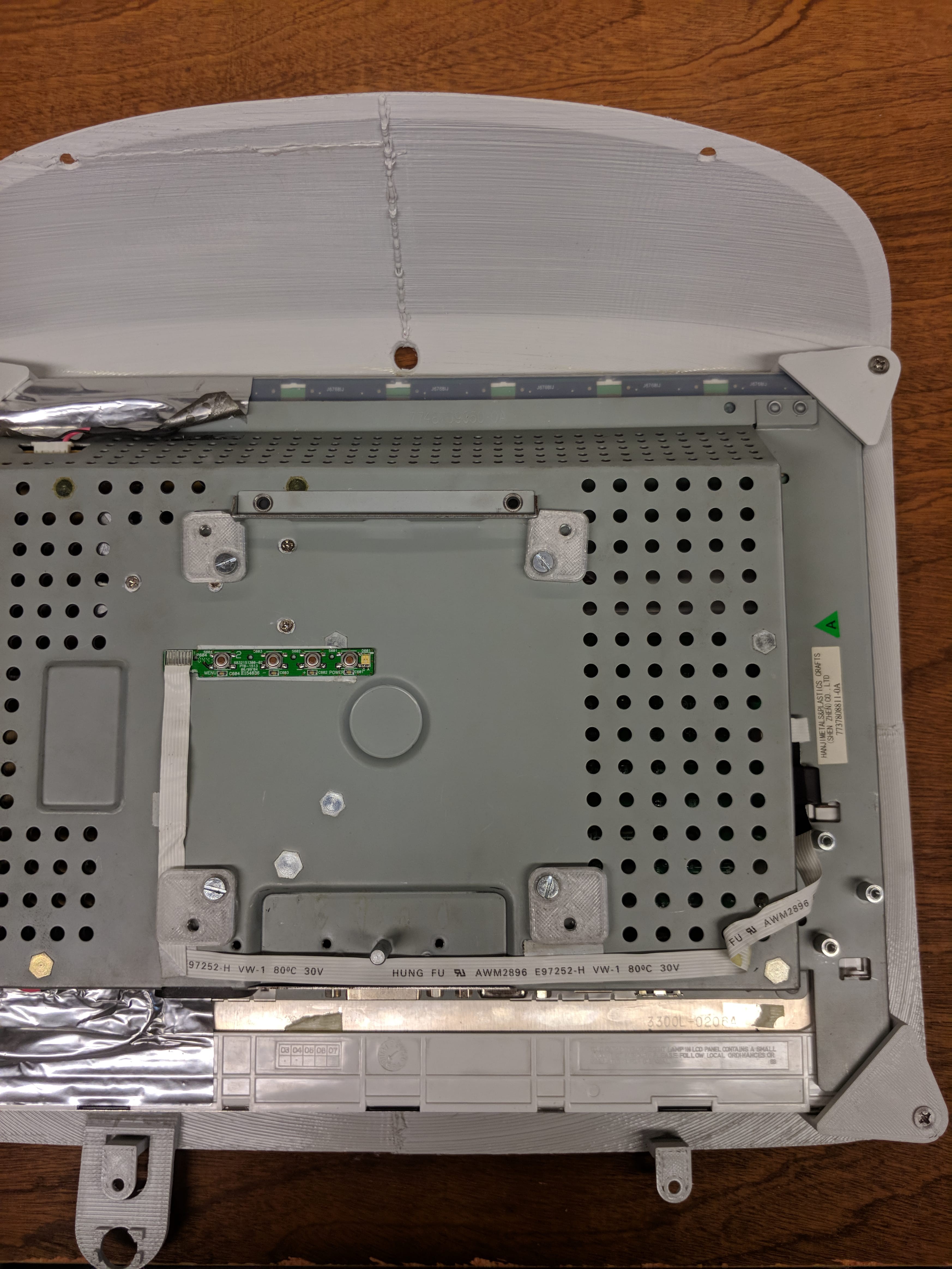 These models are also not correct, because I had to rotate the PSU to fit inside. I might still change the models on github.
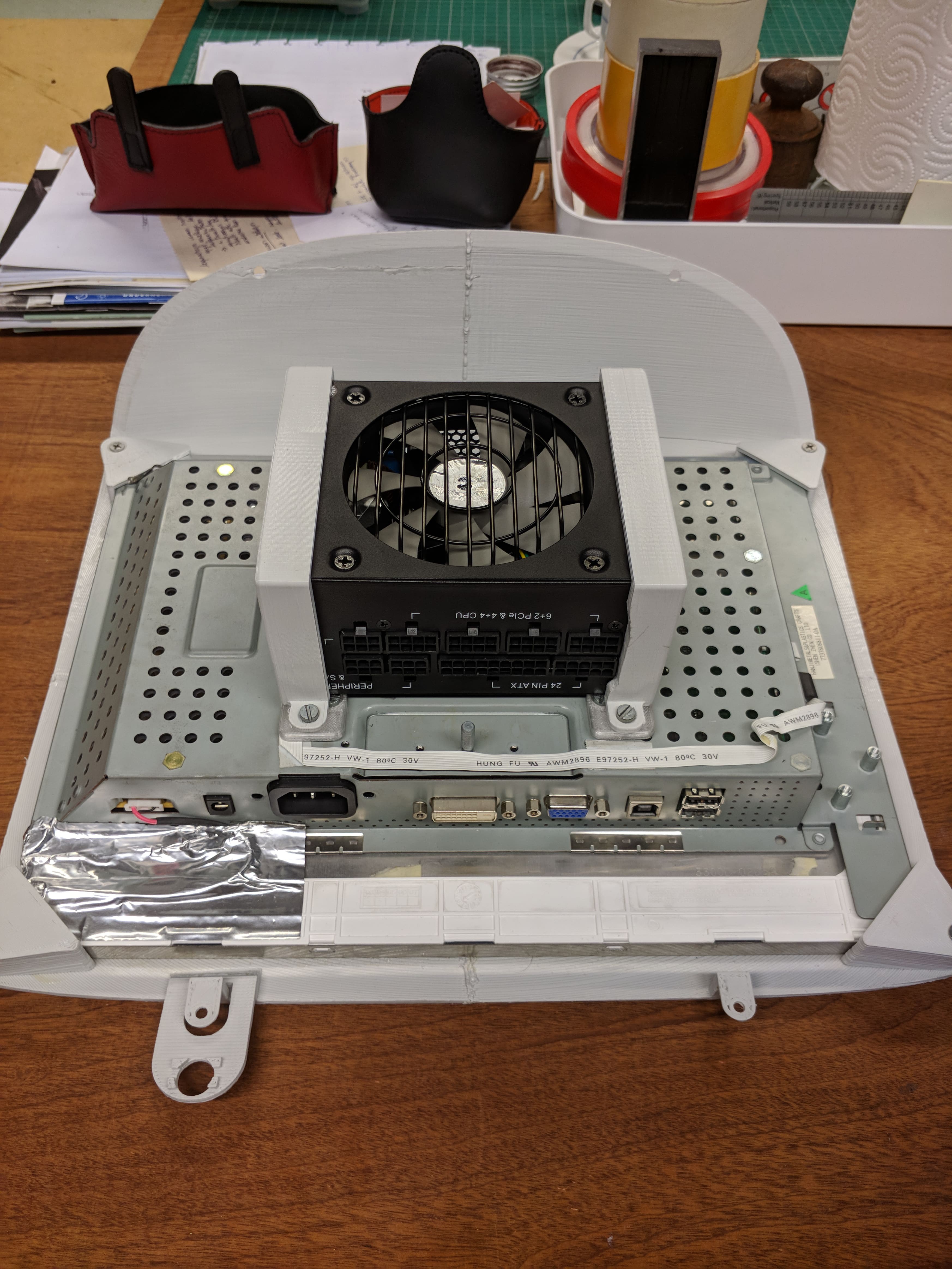


 Now fasten the front with some bolts, nuts and washers.
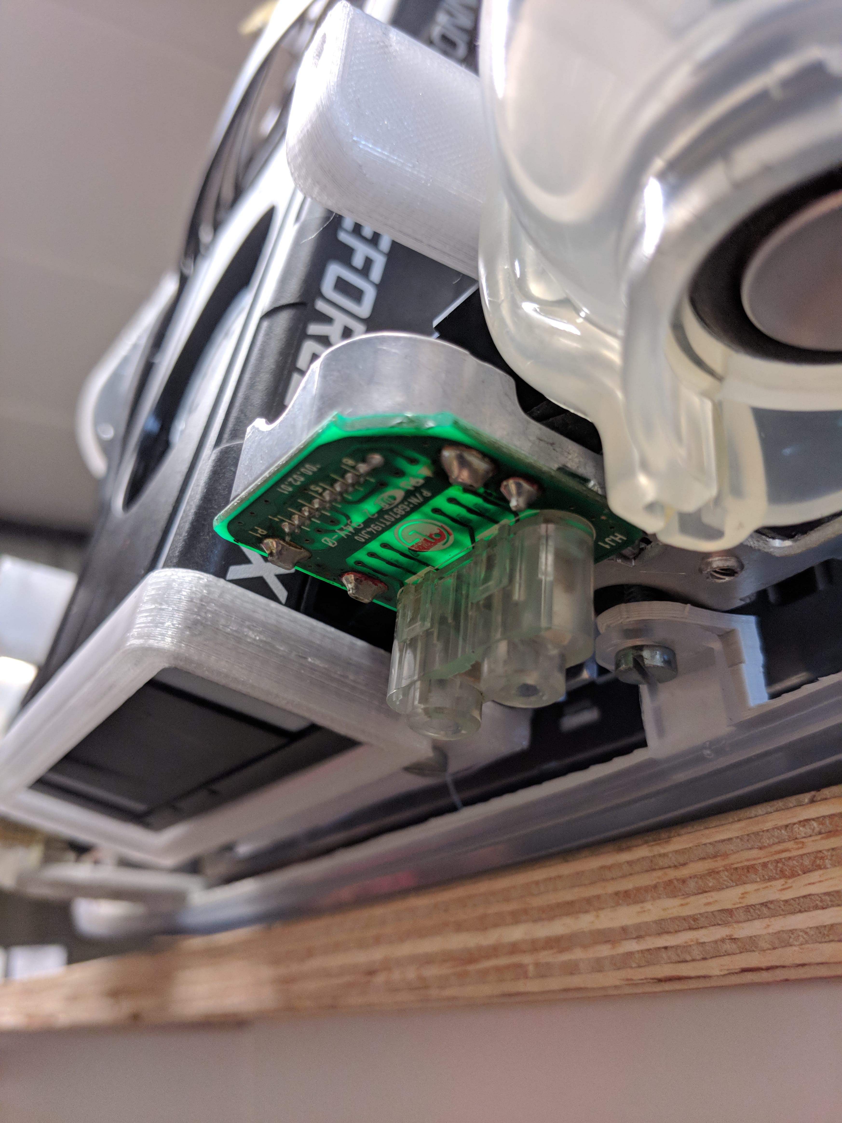
 Now put the bottom on there and screw in the bottom screws first (near the speakers)
 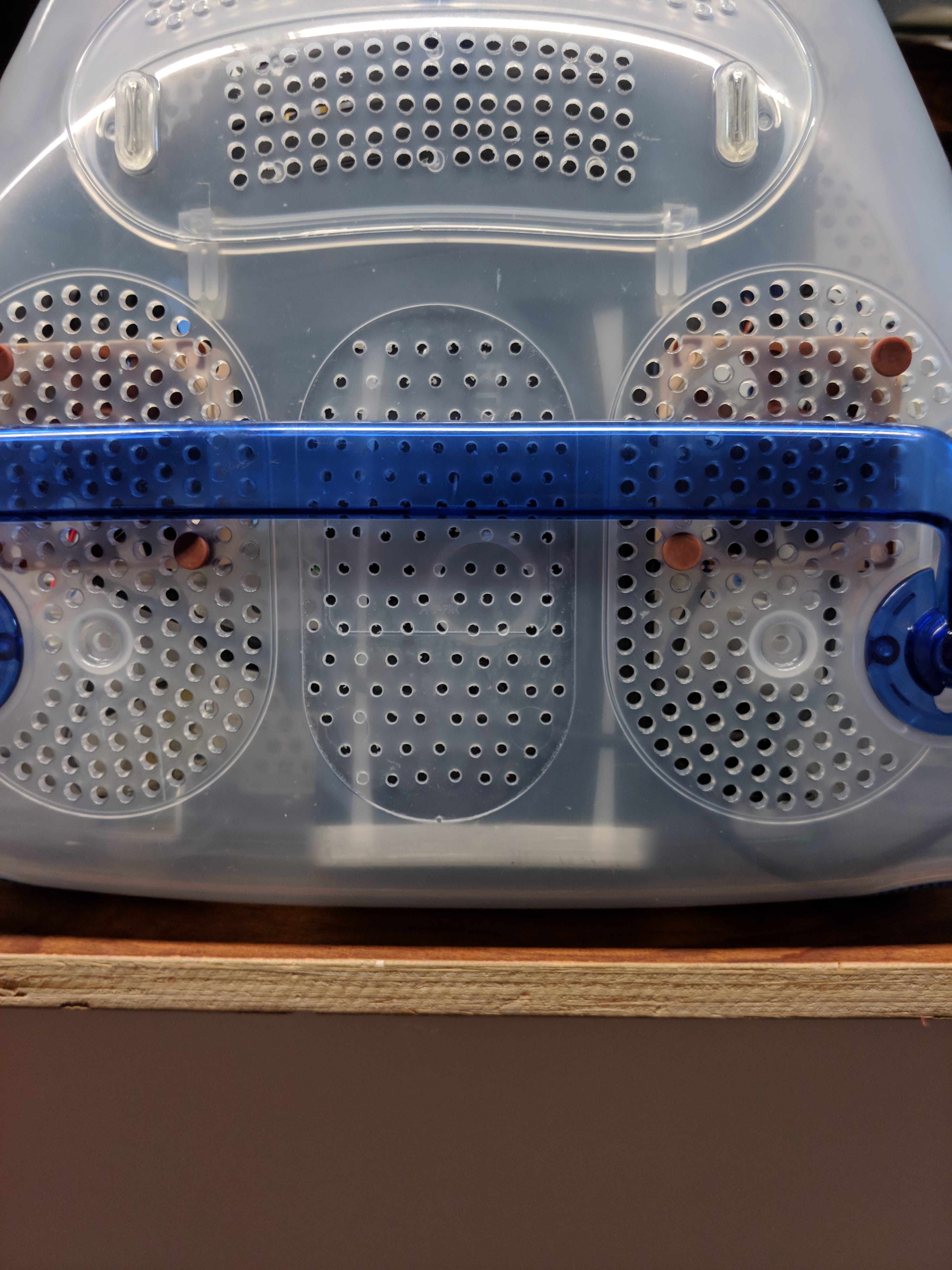 When those are secure, move on to the back and screw in the last two screws. You're done!