mitchell.dokken
-
4 layer PCB works
02/25/2019 at 16:09 • 0 commentsI only made 2 mistakes on this one, both involve the 5v rail. One mistake involves drilling a via out, the other is cutting a trace and soldering a jumper.
The firmware for the STM32 works on the first try, which is rare. Now the display is handled by the micro instead of sbc.
![]()
Big ups to @Sunshine_Jones for the boot screen quote from embedded.fm.
Currently working on bringing the linux version up from 4.13 to 4.18. Playing with -mtune gcc options in buildroot.
Learned about `ldd -v` and `patchelf`, so I'm creating a small script to help non-developers bring their favorite binaries over to this. I have this feature working with orca, which you can find here: https://github.com/hundredrabbits/Orca-c . It basically finds all shared library dependencies, copies them over, tweaks the search path for that binary, tars it, and it generates a shell script for the LD_LIBRARY_PATH update when you try to run the binary.
This week will be dedicated to getting the linux groundwork complete so I can work on full feature compatibility within puredata. I also ditched python and the curses module for the screen. Its all OSC messages over the serial port now.
-
I'm not dead
02/05/2019 at 16:04 • 0 commentsI haven't died, I just took a break. After adding some features like FM transmit and receive, I realized I really do need a 4 layer board. I added the transmitter and receiver on the I2C bus and I have bash scripts to control em. I upgraded the STM32F103C to an R series, which is a 64 tqfp instead of 48. To save room, I switched from 16 to 1 muxes to the good ol' 8-1 CD4051. Added a few more buttons so I can add features I want to add without ruining the organelle patches. Added some USB A ports to the bottom so you can plug in any other gear you want without having to solder to pads.
On the software side, I've implemented the SPI screen drawing on the STM32 now, and send all messages over the UART with puredata instead of python. I'm trying to make everything run in puredata, which I understand is a fool's gambit, but I want to see if its possible. Using lists in pd 49.1 it does seem to be possible, as long as you're willing to put in the time to understand it. I've added a waveform drawing mechanism, which seems to work really well for showing samples. In the mother.pd main patch, I have logic for launching child pd processes, so mother.pd should never close. I'm adding a 4 track looper and some other features from OP-1 in the mother patch, so building full songs shouldn't require any external gear.
Still very much a work in progress. Turns out C-media chips are only being sold by Symmetry Semiconductors, and they have MOQ of 1k sometimes. I can't get my hands on any of the USB 2.0 spec'd codecs, so I'm stuck with 48KHz 16 bit. Not a problem for now, but I do want lower latency audio. I've been on a wild goose chase reading about XMOS series USB to I2S microcontrollers, and they've really got something going there. Their XC code is readable and very deterministic, with threading and interrupts practically built-in. I do intend to follow along and create an XUF208 TQFP module with some TQFP codecs, which should all be USB 2.0. I dont intend to do any DSP on the XMOS series, but it could be a nice starting place for others.
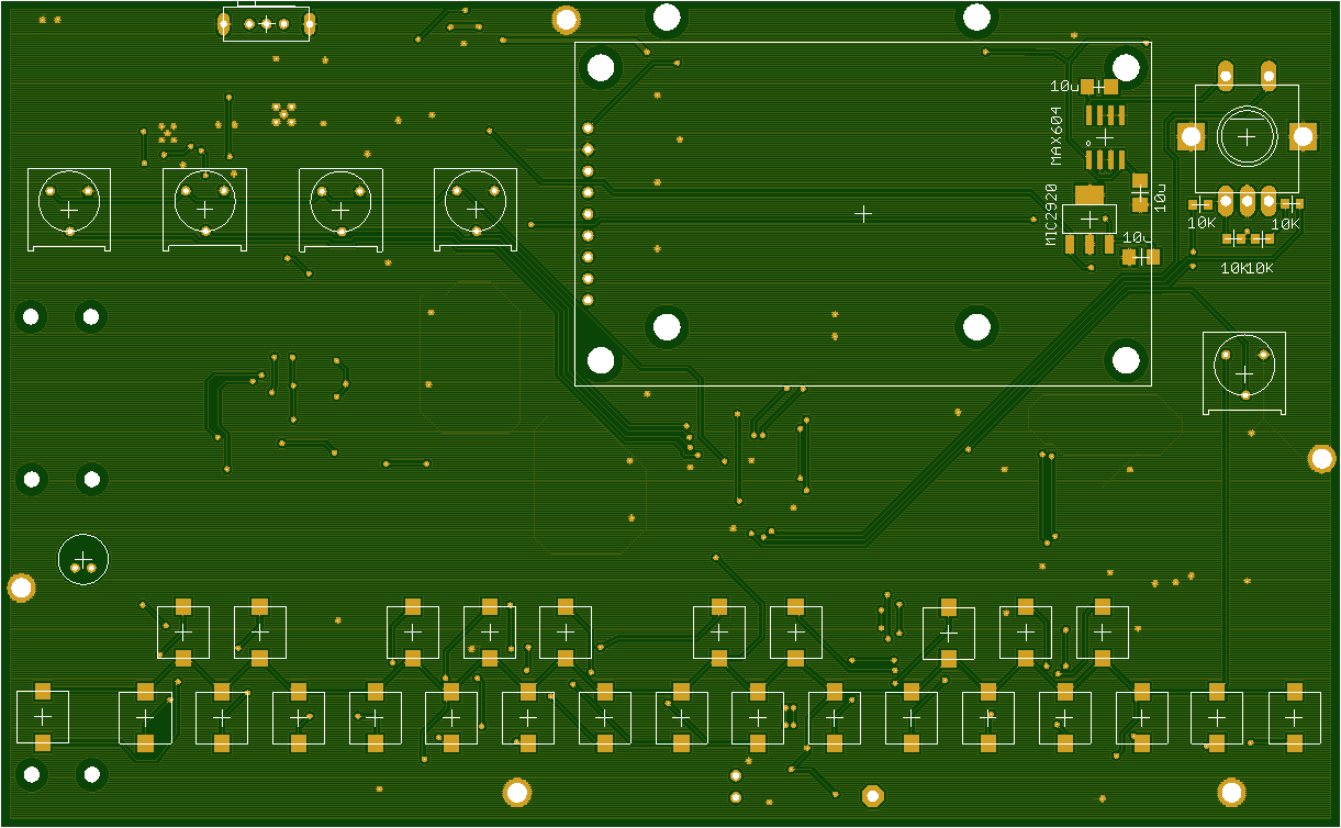
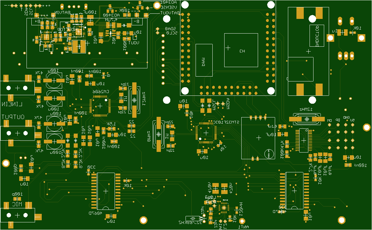
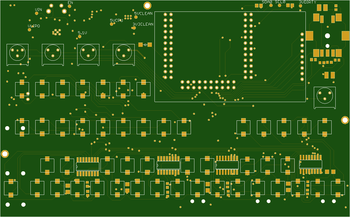
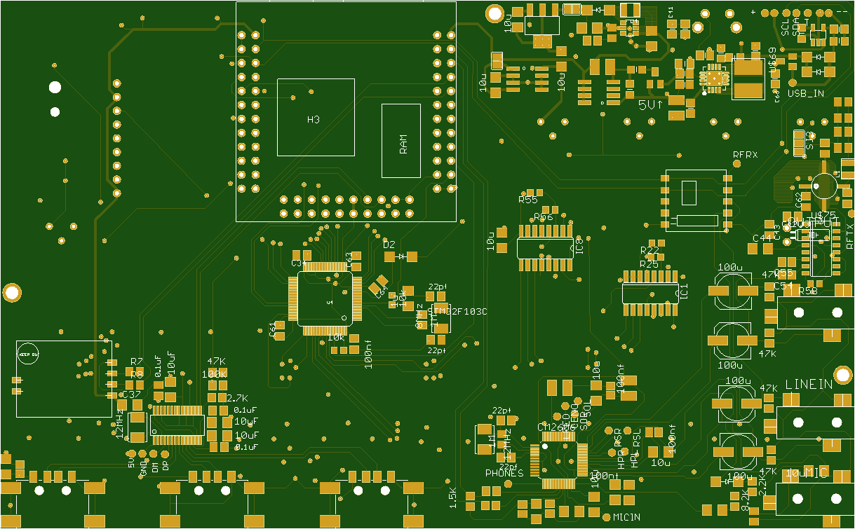
Anyway, here is what the new design looks like:
![]()
![]()
The large empty space on the bottom of the board is for a fan.
-
holy crap it actually works
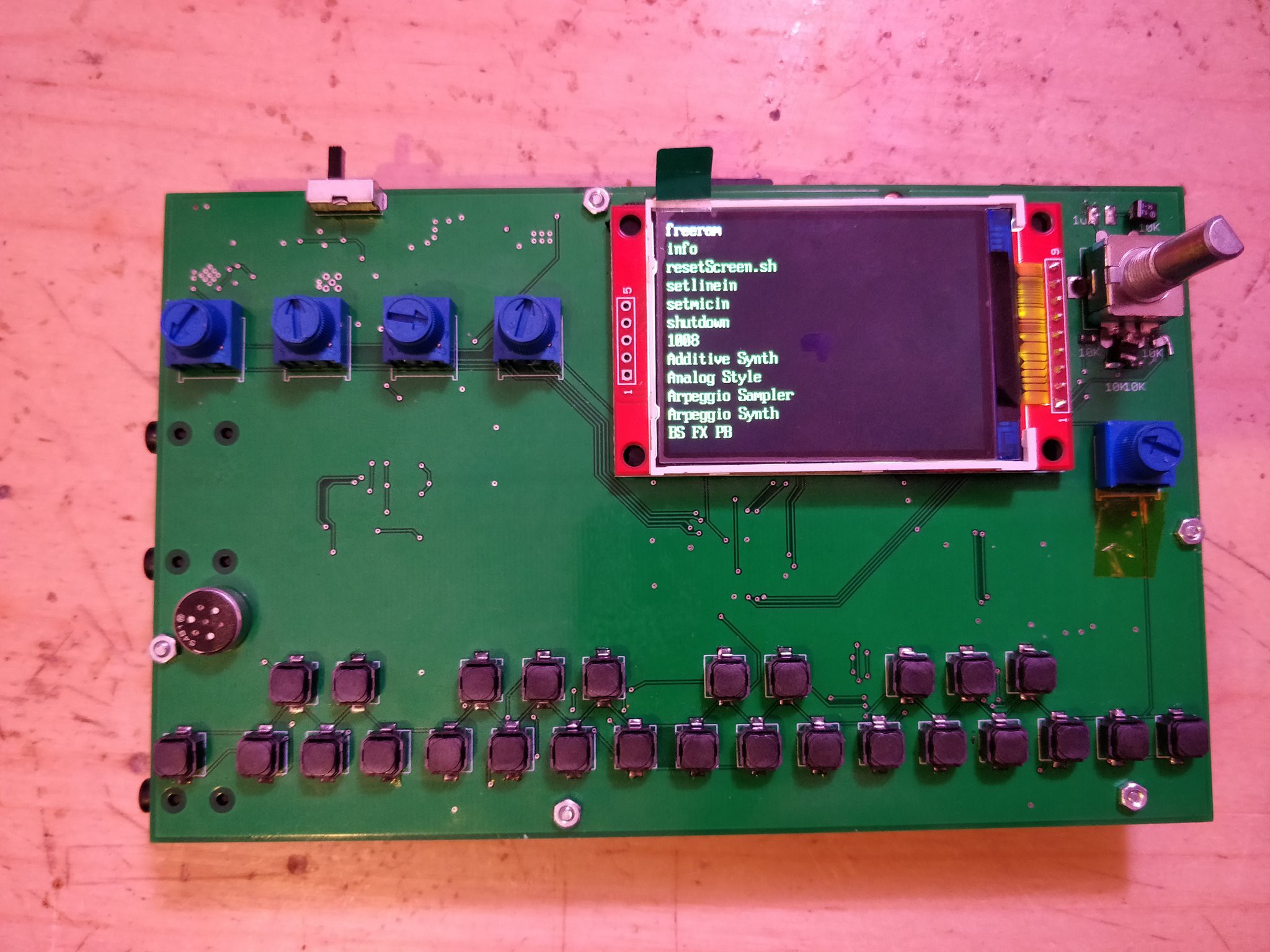
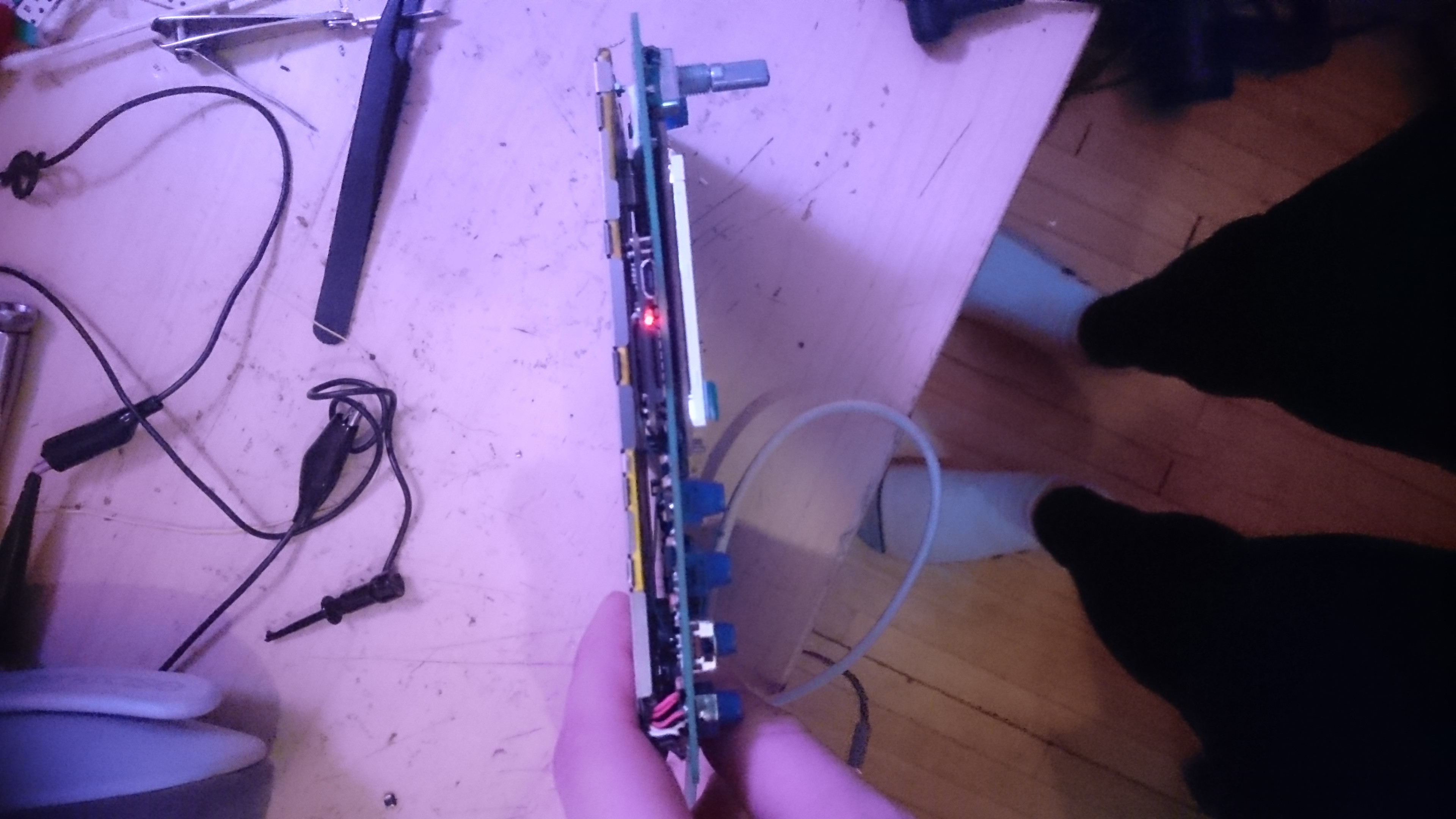
10/08/2018 at 01:05 • 2 commentsIt works! After some bodge wires and double checking everything, it successfully boots into a working clone of the organelle! Its smaller and costs about $80 to make, and its all open source! It is only a first-pass at this, I do intend to make it better.
Hopefully this post will detail how the device works in a way that makes sense.
The power supply circuit is lifted pretty much wholesale from adafruit's powerboost 1000. The li-on charger and power mux IC looked really great, and the DC-DC boost converter they used seemed extremely efficient. It also has rave reviews on people's portable emulator project, so I'd seen it around. I've never soldered qfn, so I got chipquik on my digikey order. I then realized that a power supply done in chipquik is an awful idea, but I had no other options. I slowly soldered the circuit, first doing the battery management IC, and testing along with a battery and a 5v in from a USB cable. It did what it said on the box, so I moved to the DC-DC converter. This one also seemed to do what they said it would do. Shortly after this, things fell apart.
I had spec'd out a DC boost to around 6.5, for a 5v clean output for the audio card. The nanopi's 5v line gets so polluted by all the fast switching from various sources. I used the same circuit all those cheap MT3608 boost converters from china use. They work, in my experience, and you can get 40 of them, shipped to USA, for about $6. The 5v reg is an MIC2920, just because I had them in stock. Their LDO characteristics aren't bad, either. There is another 3.3v line for the STM32, mainly so it's ADCs are a little bit cleaner. I used a MAX604, since I had it around.
I should probably explain that I got extremely lucky on craigslist a few years ago and ended up with the entire stock of a local 90's telecom that went under. I've got loads of parts, mostly jellybean stuff, but all of it is labeled and inventoried. I didn't get it that way, the labeling took months. This will help to explain the footprint size of the capacitors and resistors. I wish I could just used 0603 parts for everything, but its better for me to do what I have on hand.
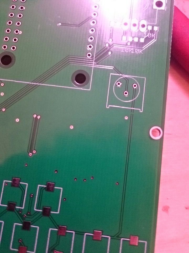
Right away the 3.3v line had a short. After hunting around, I found something I'd overlooked in eagle. I felt very stupid. Clearly a short from some previous trace before I'd added the ground plane.
![]()
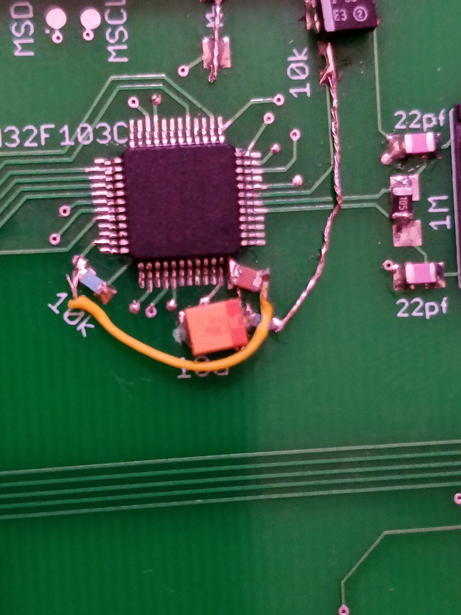
Had to use my scalpels to slice it. Swapped out the MAX604 and we were off to the races. Except the STM32 now would not flash. It turned out I'd misinterpreted the reference schematic I was looking at, and misplaced some pullups/capacitors. Bodge wires fixed that up well.
![]()
I also had to tweak the software on the nanopi, as the reset and boot0 pins have to always be initialized. I use stm32flash to do the business. Since the nanopi doesn't have a compiler, I rsync the bin from my desktop the board, then have a bash script which handles the flashing. It works reliably now!
I also misinterpreted about the same thing on the button debouncing for the rotary encoder's switch. A similar bodge occurred there.
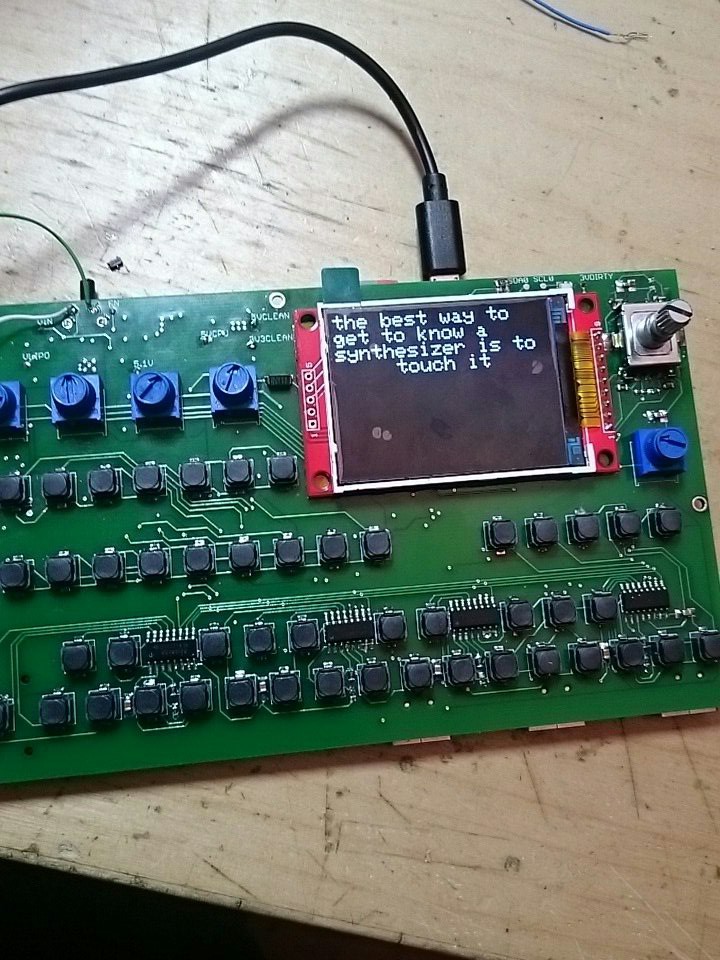
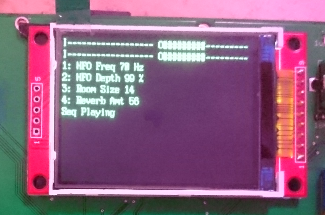
I was getting pretty scared that the 2.2 inch TFTs I ordered at the end of august wouldn't show up before the deadline, so I bought two for about double the cost, shipped locally. I still hadn't tested my footprint from the first revision, so its all pretty up in the air whether its going to work. To fit in space for a hypothetical fan that may or may not be needed, I moved the nanopi a bit, and flipped the screen layout to give me about 42mm. I knew I could flip the screen in software, I just didn't expect it to be that easy. Oh, and I messed up by one GPIO on the pinout from my prototype, so I had to tweak it in software. Then it worked like a charm!
![]()
My phone's camera is a piece of shit. It looks quite clear to human eyes, even with the screen protector.
Next up, I had to get the button array working. They all soldered into place real well, but I encountered an issue I'm sure you've all seen: the 13th button was registering as the 10th. The 10th one worked like you'd expect. There aren't any shorts in the hardware. As soon as I realized the problem, I wrote a dirty solution which worked. Stupid newline/carriage return stuff! I could have swore the OSC/SLIP protocols got around that, it must be something in puredata. So that was thankfully an easy fix.
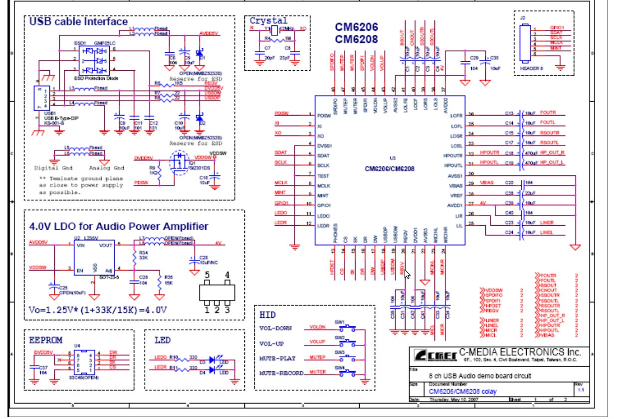
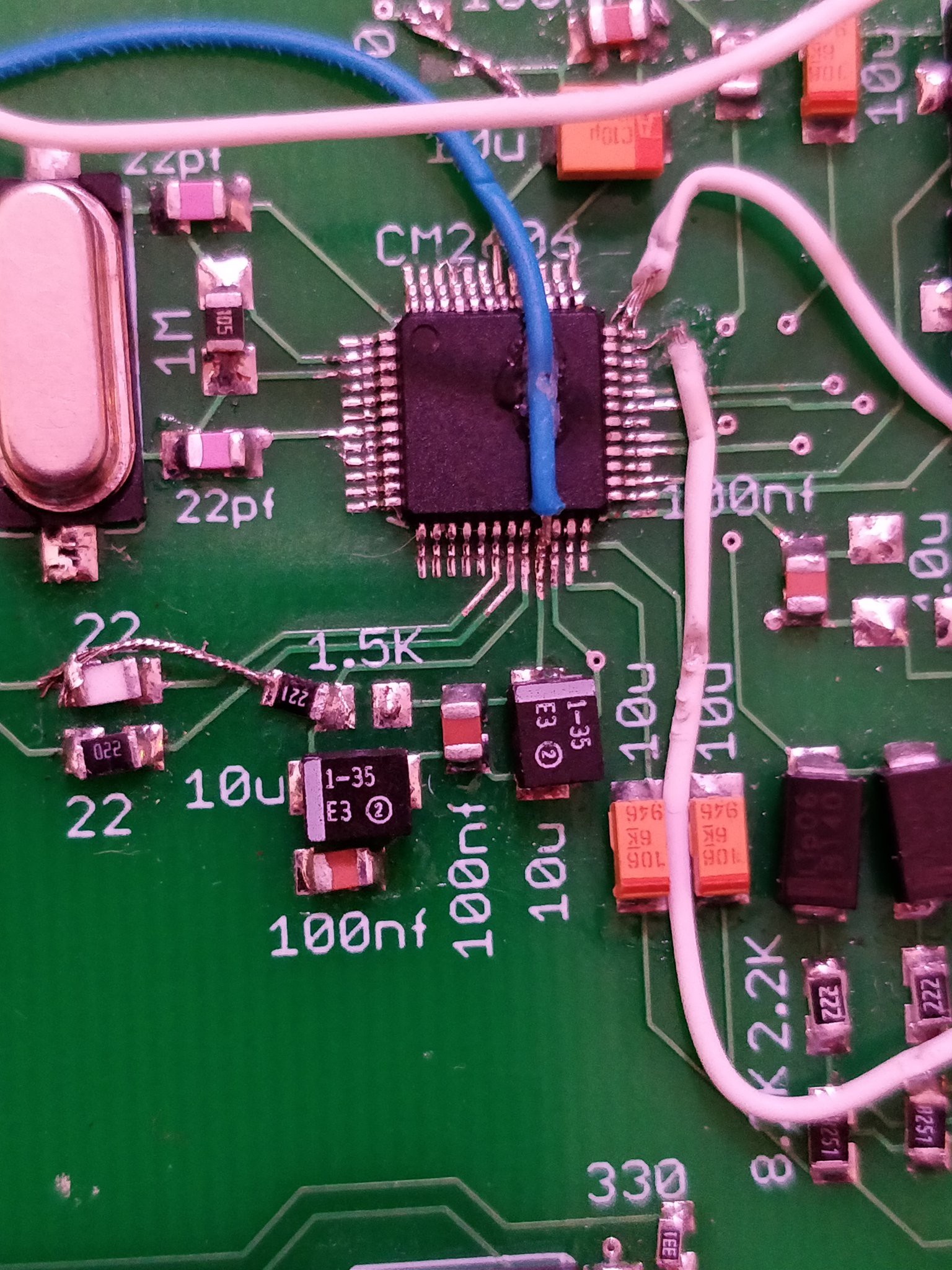
Finally, and only just today (Sunday Oct 7, the day before the contest ends) I got the USB soundcard to work. It turns out that when I ordered the chips in august, the semiconductor company was moving their warehouse from california to texas. I do not envy them. The chips finally arrived about last week. I'm not bitter or complaining, just a warning to check your sources before you hit the buy button. I was backed into a corner because I know this chip would work, but I couldn't buy it from anywhere but there. Anyway, the C-Media 6206 is used in those really cheap USB soundcards with a bunch of outputs. In my prototype it worked really well (after power filtering via DC-DC boost -> LDO)! The reference schematic I had for it is extremely blurry, poorly labeled, and really overall just bad. There was JUST enough information left after compression to get it to work.
![]()
I realized I goofed when I tied the REGV line to 5v through 1.5K ohms instead of the USB Data Plus line. It seemed like a bizarre typo, but I verified it with the soundcard I'd purchased earlier. After that, it still didn't work like I'd expect. I imagine it has to do with the 4.0v LDO for the power amp. I instead bodged again, and pulled the LOFR and LOFL lines right into the output caps. It worked!
![]()
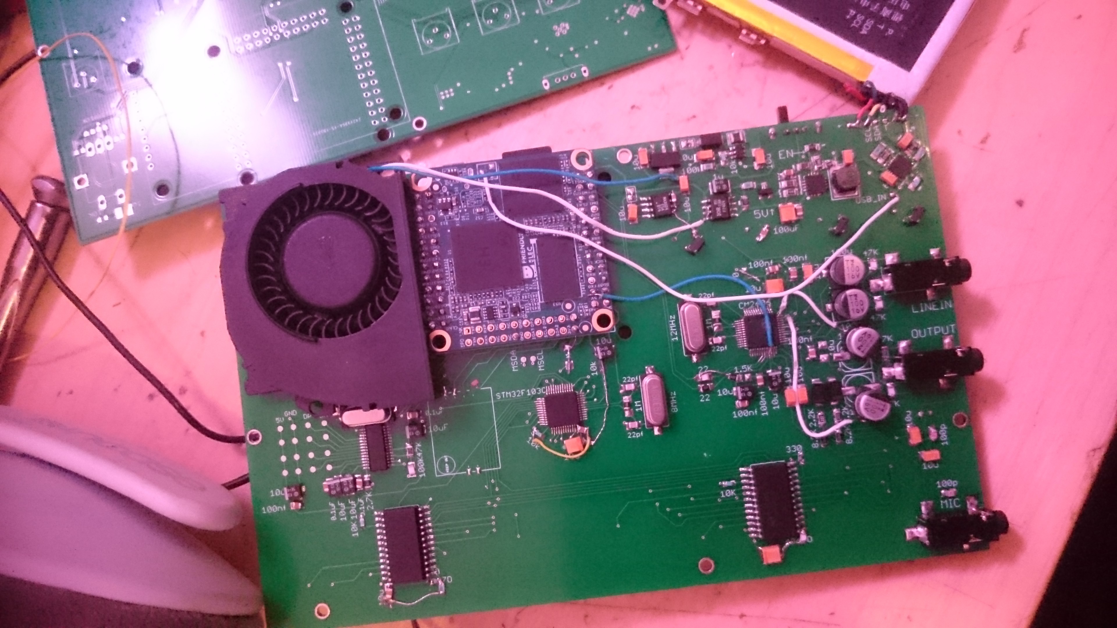
Thats the hardware part of all of this. A single toggle switch pulls the enable pin on the initial DC-DC boost converter. That takes the power from either the battery XOR the microUSB input. Then it goes straight into the nanopi, which does its own 3.3 volt regulation. A separate 5v and 3.3v are sent to the USB soundcard and STM respectively. The TFT is powered by the nanopi's 3v3 line. Those all operate as you'd expect.
![]()
![]()
![]()
![]()
The STM sends OSC messages to the nanopi over UART 1 at 115200 baud, which gets interpreted by a python script, and sent to either puredata, the screen (using the curses lib), or some system command. The OSC messages honestly fly all over the place. The STM32 sends and receives messages, python handles All of the messages, so it has to have a handler for everything, and puredata sends/recieves over OSC. Any system script ALSO sends/receives OSC using oscdump/oscsend. Its basically a madhouse of udp messaging. Python does seem to keep up well, using 3-6% of cpu at any given time. The STM reception and PD reception processes are threaded in python.
The entire linux system is something I've been working on for about a year now, I think. I started figuring out the buildroot system, how uboot/dts/drivers/kernel/userspace work, how board bring up on a new board works, and merging patches for the Allwinner H3, all in May of last year. I basically spent a few months in my room either playing Factorio or hitting make, then playing Factorio. I managed to create a config for mainline linux which included USB OTG support, ethernet, SPI, and other hardware optimizations, running a realtime kernel. I thought that was pretty cool, and I just sorta waited for some H3 design which included breakouts for the line-in inputs or the FM-in. Any would do. Instead they just kept releasing a single mic-in as the solution. It was pretty frustrating. So I went and made a PCM2906 dev board for fun, but I couldn't solve an issue or two. I put everything on the backburner.
I spent some time figuring out the organelle worked by studying their github repos. I figured they'd be easier to work with if they were written in python, or at least more accessible languages. Their code is also out of date from what they have on the market, what with drawing graphics and whatnot, so I wanted to give it a go of workin on an open source project. I ended up with a python script over a thousand lines long, using the curses module, and rewrote the puredata mother patch to work with what I'd written for the STM and python. The whole goal was to be able to load arbitrary organelle patches and have it work. It did!
Then the hackaday contest comes up and says "heres some possible money to do something", and I said yeah why the hell not. I could probably throw all this stuff together by Oct7. I got pretty lucky with my guesswork, and I have a lot to learn regarding integrating a bunch of different stuff on a PCB. Right now Its all very much a first pass, on all accounts. The PCB design was based around the kindle battery I used. The code is functional, but not without some glitches. The screen will sometimes switch all letters to about 200 up the unicode scale. The ADCS on the STM32 are noisy and give a wide range of readings. I'm using quickchip on the power supply!
I think the most important thing would be that its possible to, very cheaply, improve on stuff out there in the wild. I see the organelle only as a starting point. Its a bit of a spectrum of Teenage Engineering's pocket operators, to Critter and Guitarri's organelle, to the OP-1 (and now OP-Z). With the current setup I have the groundwork for organelle to OP-1. I am going to create a pocket operator clone using allwinner's V3s. 64MB of ram should be enough to handle all that. The OP-1 could possibly be done on a platform like this. I left the topside of the PCB bare for this reason. I could design another board with an array of buttons matching the OP-1 and hook it into another uart. Or I could take inspiration from the square inch contest and create a bunch of synth module things in a square inch, and create a backbone of busses to run everything from. Synths get really weird when you involve a networking stack, or microcontrollers running at 72MHz.
In the future, I'd love to have something like paul stroffgen's teensy audio gui. But instead of spitting out some boilerplate C code, I'd have it spit out a buildroot config, full C code for the STM32 (based on the options you selected in the gui), a BOM, and the schematic. I suppose the PCB would be up to the end user, but it would simplify the whole "how do I make this thing that I want" when you really don't know where to begin. Hiding the work behind a node-red interface seems like a really interesting take on embedded linux systems that I haven't seen before.
Anyway, I understand that I'm supposed to upload a video of it playing. I'm really awful at playing instruments, so I'll throw something up later tonight. Thanks for reading!
-
Revision 2
09/24/2018 at 02:29 • 0 commentsI know I'm cutting it extremely close to the deadline, but I think it'll be fine. Had some time this weekend to get through the laundry list of PCB mistakes, and sent off another board to JLC pcb. Needed to tweak the enable pin on the initial DC-DC boost converter so I can toggle it on and off, added the inrush current limiter, and jumpers to the 3v3 and 5v 'clean' LDO lines. This way when I do board bringup I can test each power supply separately. I had a hell of a time troubleshooting my circuit when the DC-DC shorted 5V to ground. This will make any mistakes like that less time costly. Also added more vias to the power supply components. Using chipquick as solder is probably a ~really bad~ idea for these components.
The knobs were wired in backwards, ground and 3v3 had to get switch around. Their footprint was also awful, with the output being a good 2mm off. The LQFP 48 packages had absolutely no pad footprints extending beyond the actual pins of the package, which makes hand soldering/drag soldering/troubleshooting very very frustrating. I changed the pad length from .9mm to 1.7mm, and adjusted their origins. The STM32 and audio codec should be a breeze now.
The "aux" button and the first C of the keyboard were switched around. I fixed that. Oddly, the 11 and 13th pins of the mux both register as 11. I think this is an issue with my muxing code.
Due to flipping the nanopi the right way, I had my SPI lane running across the board in an ugly way, so I made it slightly less ugly by flipping the display as well. I purposefully left all that room under the rotary encoder for some tiny blower fans, which aren't exactly necessary, but I'll feel a lot better about constant performance with one installed. It'll blow across the CPU first, power supplies second. The listing said they're about .7cm tall, 4cm square, so hopefully its true. Not much room to play with.
I hesitated on switching out the entire CM6206 codec with a PCM2906, but the PCM doesn't have any headphone driver. Since this is an extremely late revision I'd rather just stick with what I know will work.
Threw together the github repo for the linux side of things. Really creative name. I pumped the Puredata version up to 0.49.3, since it just came out and looks really promising, feature-wise. Nothing DSP related, but with ease-of-use like infinite undo/redo, intelligent autopatching, and some other niceties.
I updated the files part of this project with the last board revision, and Things are Looking Good.
Thanks for reading!
-
Lots of simple mistakes
09/20/2018 at 01:48 • 0 commentsI got the boards in about a week and a half ago. Nice job JLC pcb. I noticed a few things right off the bat:
- The TQFP-48 footprints are precisely the same size as the pins, which makes soldering and alignment really hard. I haven't been able to successfully do solder one yet, so I'll redo that part design for the next board.
- Using surface mount pads to mount the SBC is a bad idea. Its not easy to solder the further back rows. It should be through hole.
- Didn't measure inrush current before I designed the board, and this killed my DC-DC boost converter, and battery management ICs.
- Footprint for SI4720 RF transceiver is wrong. Its just wrong. I'm thinking of switching to discrete TX and RX ICs.
- Through hole design for the potentiometers is just wrong.
- Mounting screws for nanopi neo are off by about .1mm. Can't fully tighten the screws.
- I completely inverted the pinout of the neo, and now it is installed upside-down. As in, the CPU and RAM are facing downwards towards the main pcb. This is the opposite of what I wanted, and I need to completely redo it.
- The kindle battery mounts are slightly off, but they still work. Fit an M2.5 screw.
On top of that, the supplier of the CM6206 is moving their entire warehouse from CA to TX. It took over a month to get my 5 chips. In a huge 200 tray.
In the interim, I built the PCM2906 audio card and the FE1.1s USB hub projects for the square inch competition, and they both work! I've been thinking that the PCM290x would be better suited for this project, as it takes up a lot less space than the CM6206 design. I'll have to verify that on my next board revision.
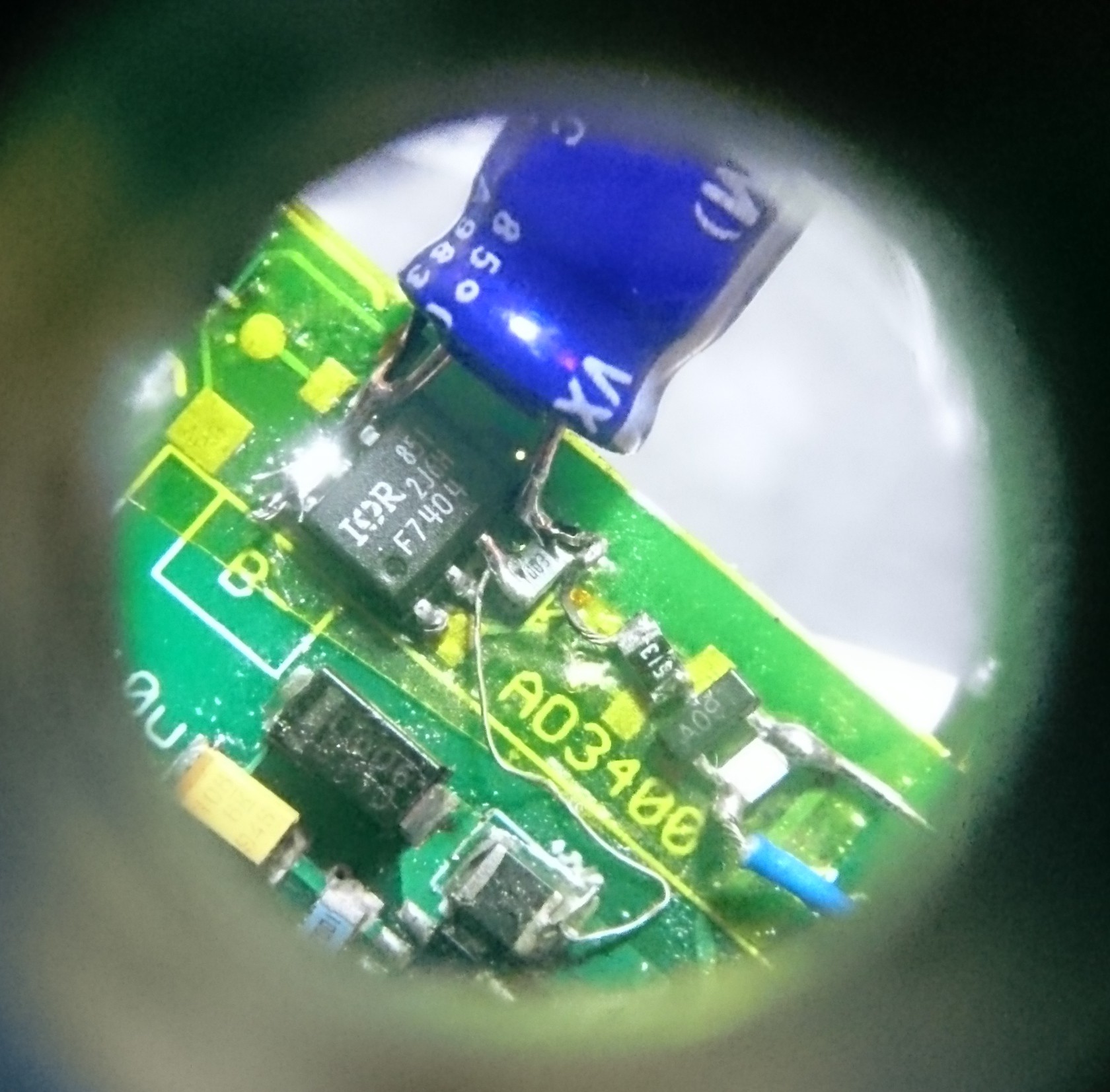
To solve the whole "blowing up my DC-DC conv and battery IC" problem, I had to get back to basics. Using the relevant application notes from ON Semiconductor, I was able to experimentally get a design that worked for me. I have a lot of parts on hand, so I used an IRF7404 P channel mosfet and an AO3400 N channel mosfet.
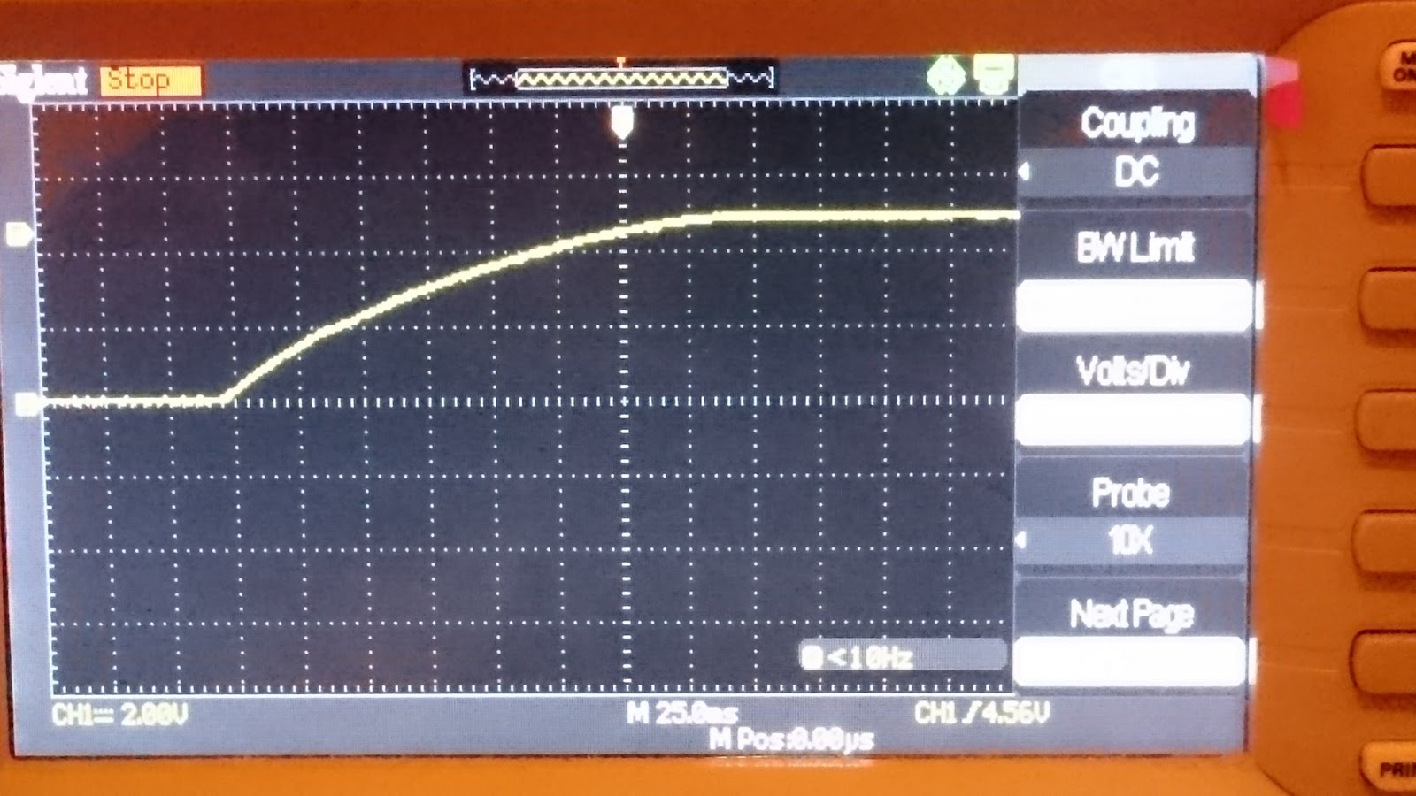
I tested it on a 5 ohm, 100uF load. I used a simple button to enable Q1, with a 10k pulldown so its default state was off. After a few tries of swapping out parts, I got a pleasant curve that wouldn't break the electronic bank.
Sorry for the photo quality, I have an Android. The final values: R1 is 100K, R2 is 50K, and C1 is 4.7uF. I could have divided all of these down, but these values were just on my desk. I was worried about the load mosfet heating up as its in the linear region too long, but as long as you don't toggle it on and off 15 times in a row, its nothing to worry about. I then tested this design on a 2.5 ohm, 1 farad load at 5 volts. It performed well.
I finally installed the circuit on some spare room on the PCB, and everything worked!
![]()
Had to use an eye loop to get this. You can see the unfortunate capacitor choice. I'll have to find SMD electrolytic variants. The ceramic and tantalum ones I tried didn't give the desired results.
During all of this, I also learned that the nanopi neo can run at 3.3 volts. As in, the 5v rail is only supplied 3.3 volts. I logged in and ran stress -c 4 for a while, and it never crashed. In this light, I've decided to forgo the main 5.1 volt DC-DC converter altogether, and use a smaller, accessory only 5v boost circuit based on the MT3806. I bought 40 of them for about 4 dollars shipped on Aliexpress.
This only complicates matters, though. I need 5 volts for USB accessories, but I also need a clean 5v line, using an LDO and ~6.5 volts from an MT3806 circuit. I also need a clean 3v3 line for the STM32, and a 3v3 line for any other accessories, such as the USB WLAN card. I measured it drawing upwards of 250ma in bursts during brief testing.
Anyway, I have the kindle battery working, the battery mgmt IC doing its business, a soft-start switch, and thats good enough for board 1. I'm going to make another board and get it here a week or two before the competition ends and prove the concept.
Thanks for reading!
-
Boards and parts ordered
09/02/2018 at 06:20 • 0 commentsSpent a few days creating a schematic to contain my current protoboard project, with some other additions I'd like to try when the parts come in.
Right now the board is at 96x156mm, which is a bit big. Its constrained by the kindle battery I've chosen, so we'll see if its a good fit for the hands.
Right now it has the bare minimum for user input. I last minute added an SI4720 for some radio stuff, a mic input, and alternative (and most likely better) designs for battery management/boost converter. They're taken from adafruit's powerboost 1000c, which is a proven design. I tweaked some of the regulators based on what I have in stock. Added a USB wifi card (MT7601U) I found on aliexpress, which is supported in the mainline kernel. Makes ad-hoc UDP-OSC multicast stuff seem more plausible, too.
Unfortunately Friendlyarm raised the price of their nanopi neo core boards from about $9.99 to $18. Not too big a deal for one, but I'm making a few for my friends. Bummer.
![]()
![]()
After I sent this off to jlcpcb, I decided to try my hand at a "what if" situation, and designed some of this synth in the style of the 1 square inch contest. I figure I could take a modular approach, so if you wanted, say, a 4 in/ 4 out soundcard, you could plop a tiny PCB on to your main PCB and be off to the races. Right now I've got a decent audio mux, the RF transceiver, a PCM2906 2in/2out soundcard, and an FE1.1s usb hub each on their own < 1 inch PCBs.
I'm envisioning a sort of main bus backbone, eurorack style, on the main or carrier PCB, with room for all these little 'expansion cards' so the end user could build the synth they want. This'd make adding more buttons/knobs on the top easier, too, as you could create a PCB to mount to the front and hook into, say, a USB or UART interface.
Puredata Portable Synth
Buildroot-based puredata synth, using the nanopi neo core and a CM6206 USB soundcard

 Sorry for the photo quality, I have an Android. The final values: R1 is 100K, R2 is 50K, and C1 is 4.7uF. I could have divided all of these down, but these values were just on my desk. I was worried about the load mosfet heating up as its in the linear region too long, but as long as you don't toggle it on and off 15 times in a row, its nothing to worry about. I then tested this design on a 2.5 ohm, 1 farad load at 5 volts. It performed well.