 uri.shani
-
1Design PCB name card (optional)
I thought of getting into the details about how I designed this card / tag PCB, but quite frankly I'm really new to this, and I still have a lot to learn. Therefore, here are my resources:
- My PCB art youtube video playlist.
- A medium article on the subject.
- svg2shenzhen Inkscape plugin.
- @Andrew Sowa's blog.
There were tons more places I dug, mostly KiCad forums discussions. Some google-fu was important for me.
-
2Part selection and electrical design
As I've written in the project description, I tried to keep both the cost and the complexity of the circuit as basic as I could. The ATtiny13 has 2 PWM pins, I could easily program it using the Arduino IDE, and I caould use the ADCTouch library with it. If you wish to design your own circuit, keep in mind the current draw for driving the LEDs when choosing your power source. Besides that, you can copy the schematic drawing for the bare- minimum circuit shown in the microCore readme. Or use the schematic I used, found in the files section. Note - when ordering the uC, check to see it is 150 mil wide and not 200 mil which will not fit the footprint.
-
3Solder parts
I tried to keep placement of the parts easy to understand, and in v0.2 I kept the values for the parts visible on the back silkscreen for easy reference. Hand soldering is best done with 0.4 mm no-clean solder wire (except for battery holder and pin). I did not try reflow yet, so I have no comment on that.
-
4Install Arduino libraries & cores
Install the ADCTouch library into your Arduino IDE. If you are using ATtiny13a like me, you will need microCore. If you are using a ATtiny25, you will need ATtinyCore.
-
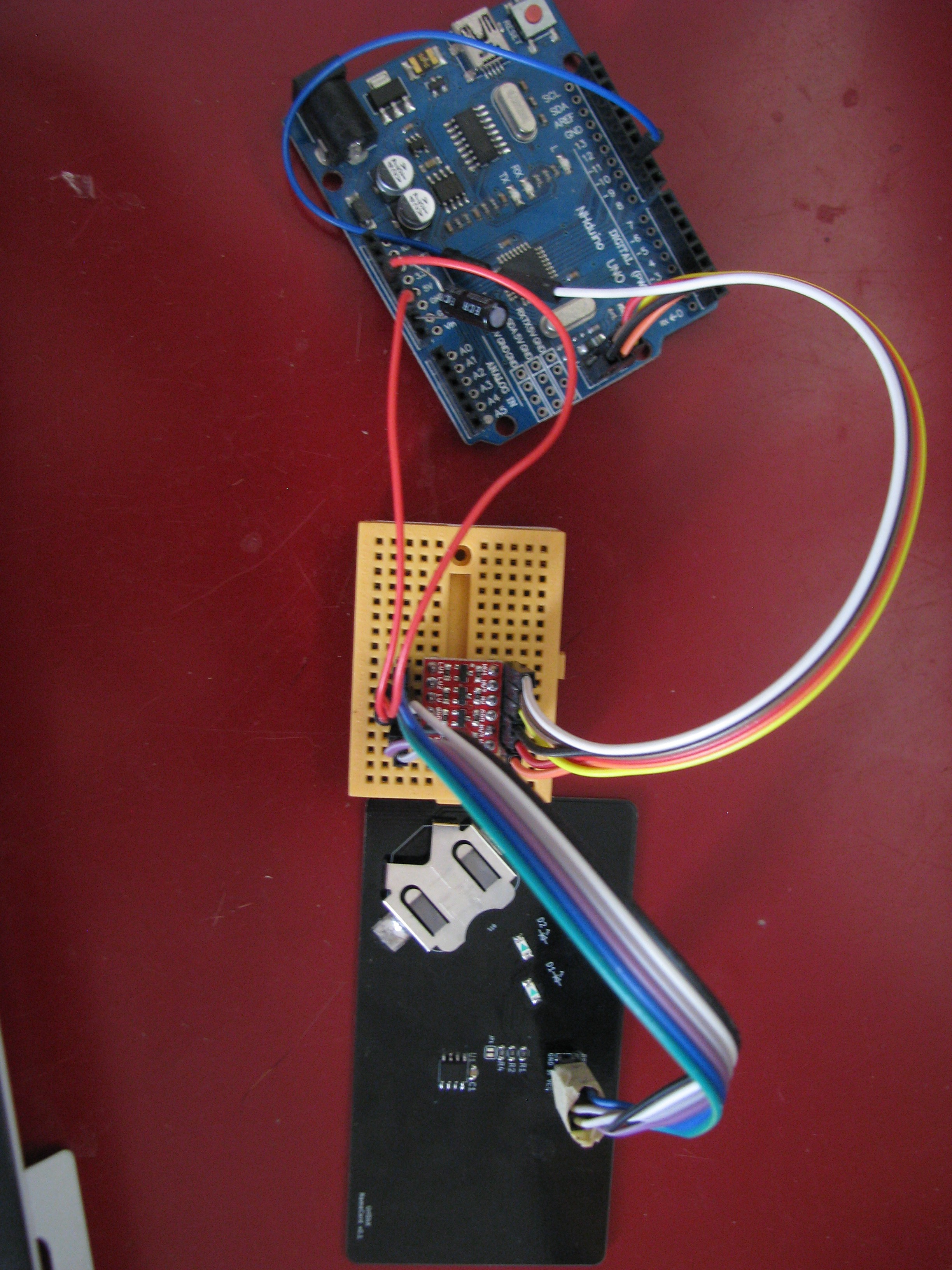
5Connect card to progrmmer
I used a spare Arduino Uno as a programmer, using the Arduino as ISP sketch in the IDE's examples. Since the Uno runs at 5V, I used SparkFun's Logic Level Converter (Mouser #474-BOB-12009), and soldered a 2x3 header to the card's ICSP. I hope to get my hands on some pogo pins soon so I can use these instead of the header.
![]()
If you intend on using pogo pins, note that on v0.2 of the PCB the center of the ICSP header is located at 40 mm left and 12.5 mm down from the top right corner, when looking from the back side.
-
6Program the microcontroller
I've attached three Arduino sketches in the files section. One is the original breathing animation, another a fixed flickering effect, and the third a pseudo-random flickering animation. I found the best looking one to be the breathing one, though the most practical and best performer was the pre-defined flickering sketch.
Notice that the pins connected to the LEDs are inverted. You can see my update on the subject above, but mainly if you edit the code make sure you write LOW to light up the LEDs, or 0 to the PWM registers OCR0A / OCR0B. Turning the LEDs off will be by writing HIGH.
I've also included the spreadsheet I used to convert the breathing animation from a function to PROGMEM'd values, so you can go ahead and use that to create or edit your own.
-
7Start the program & calibrate
Pop a fresh CR2032 in the battery holder, and the LEDs will light up for 2.5 seconds. while they are lit, place the card away from you, so calibration of the touch sensor will not be affected by your hands.
That's it. Once the LEDs turn off, the calibration of the uC has completed, and if you touch the left side of the front of the board and the ground plane on the back, the LED animation will begin.
Cap-sense name card
Combine PCB art and cap-sense activated LEDs to create a worthy maker name card
Discussions
Become a Hackaday.io Member
Create an account to leave a comment. Already have an account? Log In.