-
1Get prepared
Get prepared by checking that you have all the required parts ready.
Parts
- DFRobot CurieNano - A mini Genuino/Arduino 101 Board
- Micro USB cable
- Lithium polymer battery (LiPo around 850mAh, i.e. Sparkfun PRT-00341)
- USB LiIon/LiPoly charger (i.e. Adafruit Micro Lipo - USB LiIon/LiPoly charger)
- Power switch (i.e. Adafruit Switched JST-PH 2-Pin SMT Right Angle Breakout Board)
- 2x XBee 1mW Series 1 (WRL-11215, 802.15.4)
- DFRobot XBee USB Adapter V2 - Atmega8U2
- Raspberry Pi 3 Model B+
- microSD
- Power supply for the Raspberry Pi
- Pisound Audio interface from blokas.io (including 2 knobs, 4 spacers and 8 screws)
- 2mm 10pin XBee Socket - SMD (PRT-10030)
- Glove (a thin glove pref. without fingers)
- Some pieces of elastic textile
- Velcro
- Sewing yarn
- Thin insulated cable
Tools
- Soldering iron
- Solder
- Pliers (for electronics)
- Scissors
- Needle for sewing
- Insulation tape
- Marker pen
- Ethernet cable
Software
- GePS PureData package
- PureData vanilla distribution
- Arduino IDE
- Arduino/Genuino 101 Plug-in (download inside the Arduino IDE)
- A serial terminal client like minicom, CoolTerm or Putty
- ssh
- git
- ansible
-
2Load the code to the sensor unit
Before soldering anything to the CurieNano, we test if the setup works.
Open the Arduino sketch from the repository arduino/sensor_data_tx/sensor_data_tx.ino and modify it for testing. We want to transmit the sensor data through the USB connection. For that to work, all references to the Serial1 instance have to be changed to Serial (drop the 1), which corresponds to the serial port at the USB interface.
Now the Arduino IDE needs to know how to communicate and program the CurieNano: In the Tools Menu select the following options
- Select Board: Aruino/Genuino 101 (the one you installed in the preparation step)
- Select Serial Port: dev/cu.usbmodem1421 (the numbers in place of 1421 may vary)
- Select Programmer: AVRISP mkII
That's it. Verify and upload the sketch to the CurieNano.
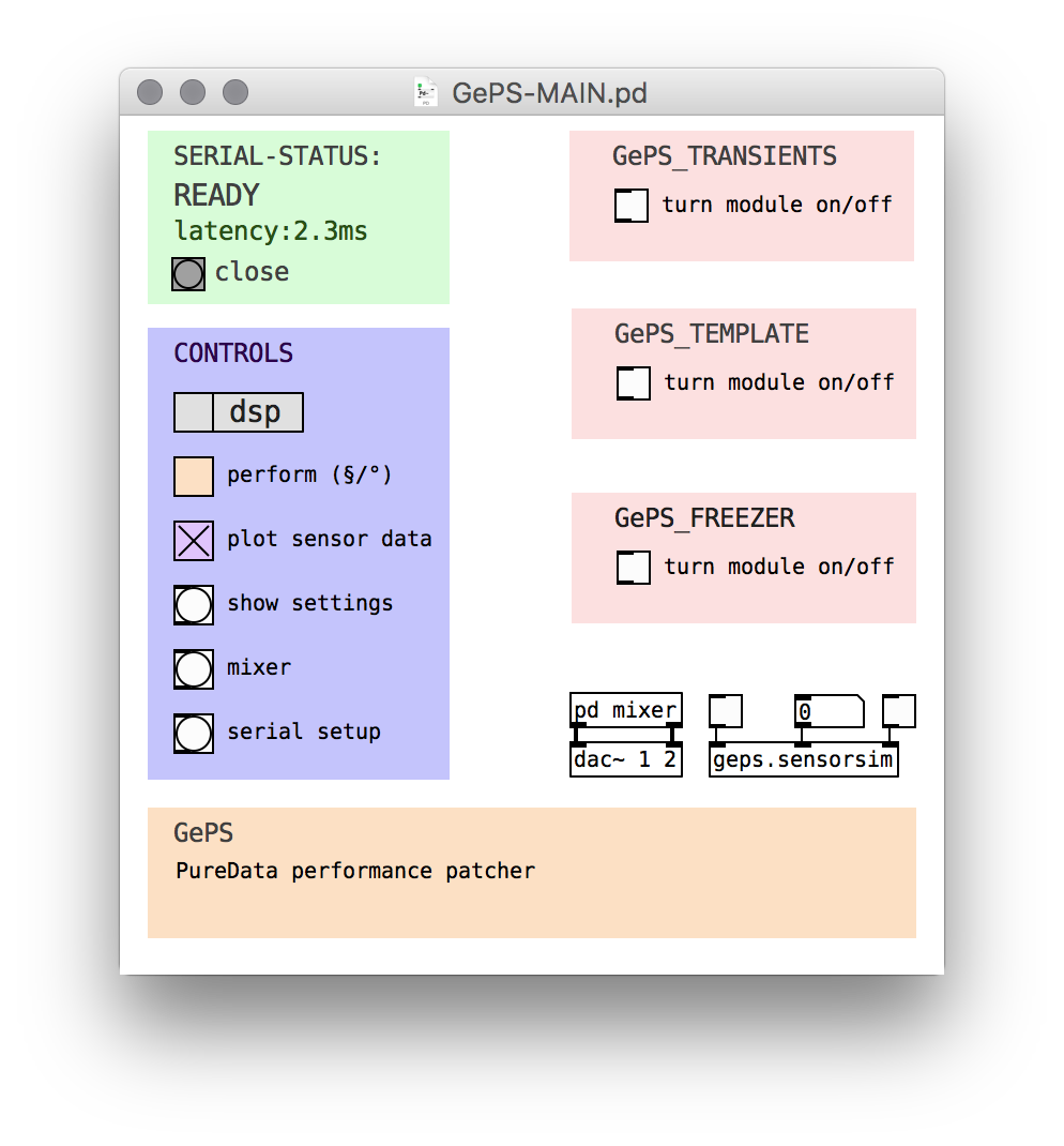
Open the PureData sound module for testing (pd/GePS-MAIN.pd in the repository)
Open "serial settings" in the CONTROLS panel. Check if the Pure Data patcher will connect to correct serial port. You can get a list of available ports by click on the "ports" button. Enter the correct port number where indicated in the comment.
Use the open/reset button in the SERIAL-STATUS panel of the MAIN patcher to connect. View the parsed sensor data by clicking "plot sensor data". Move the unit and observe the plots.
![]()
If this works, proceed and undo the changes in the Arduino sketch. We want to connect to the XBee as soon as it is soldered to the CurieNano. Upload the sketch (you won't see any sensor data in PureData anymore).
-
3Configure the XBees
Prepare
- Label the XBees with tape and marker pen, one "TX" and the other "RX"
- Plug the "TX" into the XBee USB adapter and connect it to your computer.
Depending on the serial terminal client you use, the connection procedure may vary. In this instruction we will use "minicom", installed with your favourite package manager on your favourite operating system.
Minicom connection instructions
In your favourite terminal emulator enter the following command (The baud rate of 9600 is the XBee default rate, it will change to 115200 after successful configuration below).
minicom -D /dev/cu.usbmodem1421 -b 9600Use these commands to control your session:
- Ctrl-A A or Meta-A* to add linefeed
- Ctrl-A E or Meta-E* to turn local echo on
- type the AT-commands IMPORTANT: the XBee is in programming mode only until 10s after establishing the connection. So hurry up or disconnect/reconnect.
- Ctrl-A X or Meta-X* to exit and reset
* In Mac OS X, the Meta-key is "Esc".
For more information / options on Linux/Unix read this article: 5 Linux / Unix Commands For Connecting To The Serial Console.
Configuration
- With the connection open, type the commands as shown in the table "XBee configuration commands" below, using the command parameters for the TX unit.
- Close the connection and unplug the dongle. Swap the TX unit with the RX unit and connect it again.
- Open the connection in CoolTerm and type the commands as shown in the table below, now using the command parameters for the RX unit.
- Close the connection and unplug the dongle. You can leave the RX unit plugged into the dongle, as it will be used like this later on.
XBee configuration commands, step by step
Command TX RX Comment +++ Enter XBee programming mode. Don't press return, but wait until the XBee responds with OK. All following commands will be sent by pressing return. ATRE Reset configuration of XBee. ATMY 2 1 Set local ID. ATDL 1 2 Set ID of unit to connect to. ATID 1115 1115 PAN ID (Personnel Area Network ID) value can be anything from 0000 to FFFF. Two units communicating with each other need to have this set to the same value. ATBD 7 7 Baud rate, this value need to be the same on both XBee modules, so they can talk to each other. You need to choose a baud rate of 115200 once you reestablish the serial connection in order to program / communicate with the XBee. ATCH 0E 0E Set channel. This can be any HEX value between 00 and 1A. 0E is an example. If you use multiple units (GePS) at the same time, make sure they use different channels. ATWR Write configuration to XBee memory. Refer to the XBee Command Reference Tables if you need detailed information on the AT commands.
The channel ID is superior to the PAN ID, if you use multiple units (GePS), they can use the same PAN ID, but not the same channel ID.
The XBees are ready to establish communication between sensor unit and sound module!
-
4Connect the XBee to CurieNano
![Parts overview Parts overview]()
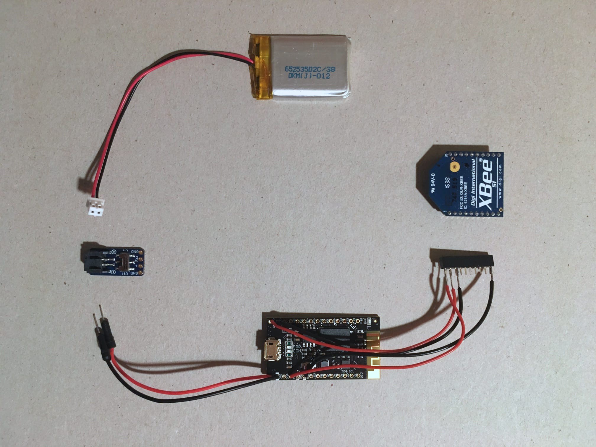
Parts overview You will need the CurieNano, the 10pin XBee socket header, and the XBee for this step. Heat up your soldering iron, prepare some cables and you're ready to go.
Connection table
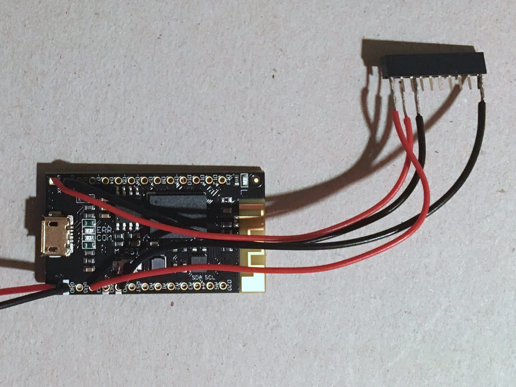
Choose the cable lengths wisely. Depending on what glove you use you need to comfortably reach the parts positions with the cabling attached. Solder the connection as shown in the connection table below.
Curie Nano XBee power switch GND (use the one next to RAW) GND RAW SW GND Pin 10
(left lower corner on logo side)3V3 Pin 1
(left top corner on logo side)D0/RX Pin 2 D1/TX Pin 3 ![]()
Once all the connections are soldered, label the pin 1 location on the XBee socket header (to avoid connecting the XBee the wrong way). Then test if the unit transmits the sensor data wirelessly: Attach the XBee to the socket header, plug in the battery to the power switch, attach the receiving XBee to the USB adapter and hook that one up to the computer.
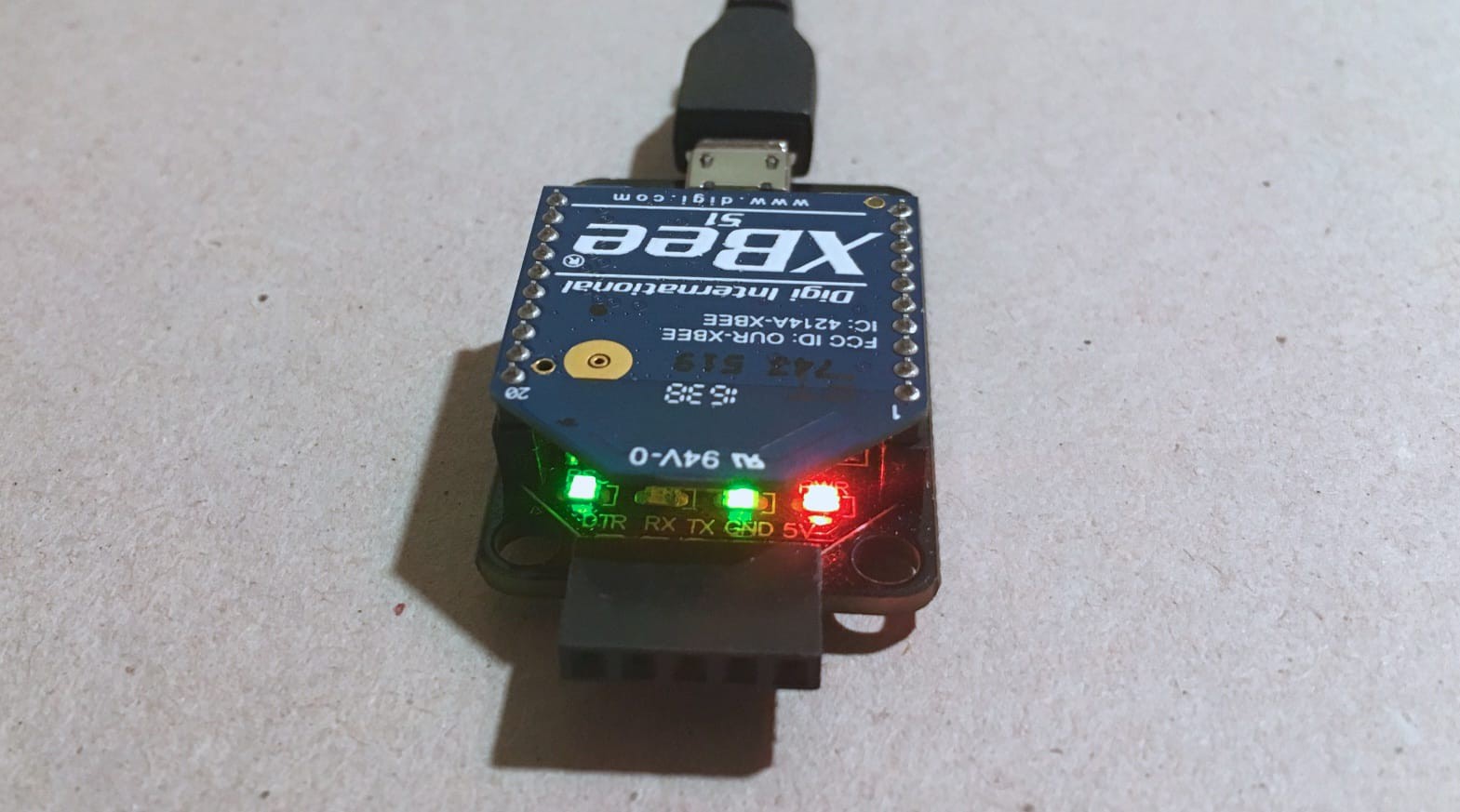
Turn on the sensor unit. The LED near pin 13 will turn on, and shortly after the green LEDs on the USB adapter underneath the receiving XBee. Again, use the Pure Data sound module to test / plot the sensor data (instructions in Step 2).
![Receiving XBee Receiving XBee]()
USB adapter with the receiving XBee attached, status LEDs showing receiving sensor data If everything worked well, your GePS sensor unit is technically ready, only thing left: Sew it to the glove start composing!
If not, check the following:
- Correct Serial port in the PureData serial configuration?
- CurieNano and peripherals well connected? The green LED should be on
- Test the soldering connections
- Check that the Arduino Sketch (sensor unit code) is loaded to the board without errors
- Check if the XBees (especially baud rates and sender/receiver id) are configured properly
-
5Building the glove for the sensor unit
We discussed the upgrade of the sensor unit in an earlier build log (https://hackaday.io/project/160886-geps/log/154025-sensor-hardware-integration). In the very end you can see first attempts to layout the glove parts. The new form factor brings new requirements like placing more parts in the glove in different places, but also the opportunity to place the XBee transmitter outside the glove, to achieve better radiation characteristics.
For this step you will need a needle and sewing yarn, scissors, a glove that you can cut into pieces without feeling sorry, and some pieces of textile and velcro. If you like you can of course dust of your sewing machine! :-)
Curie Nano
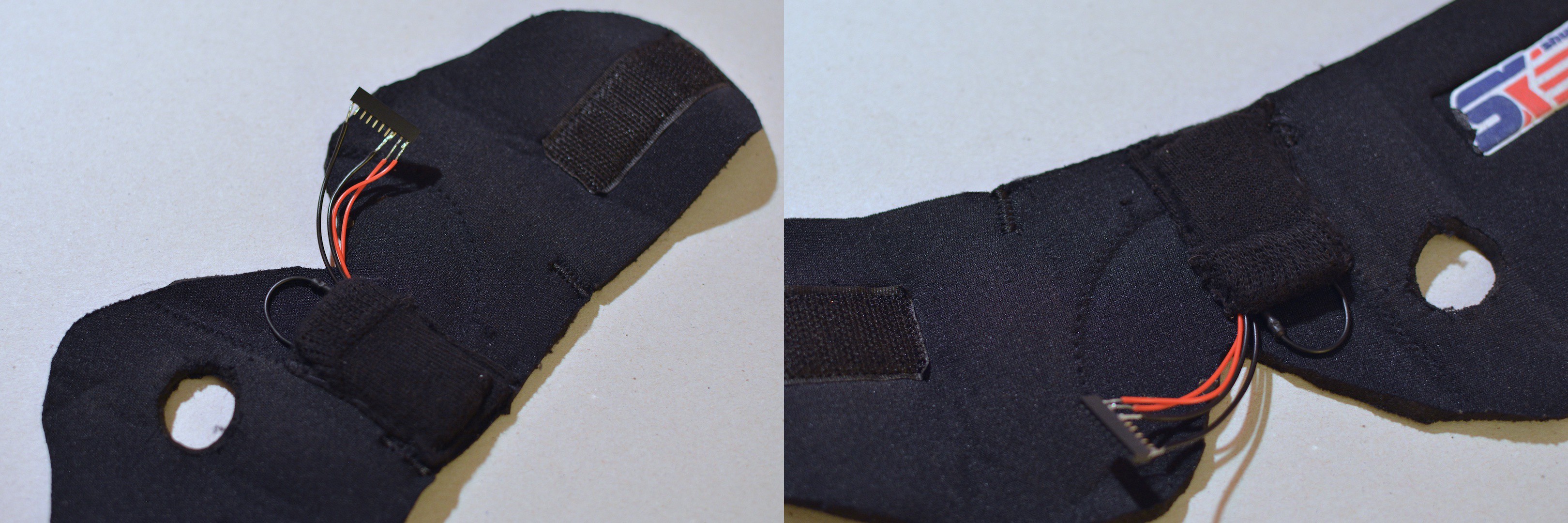
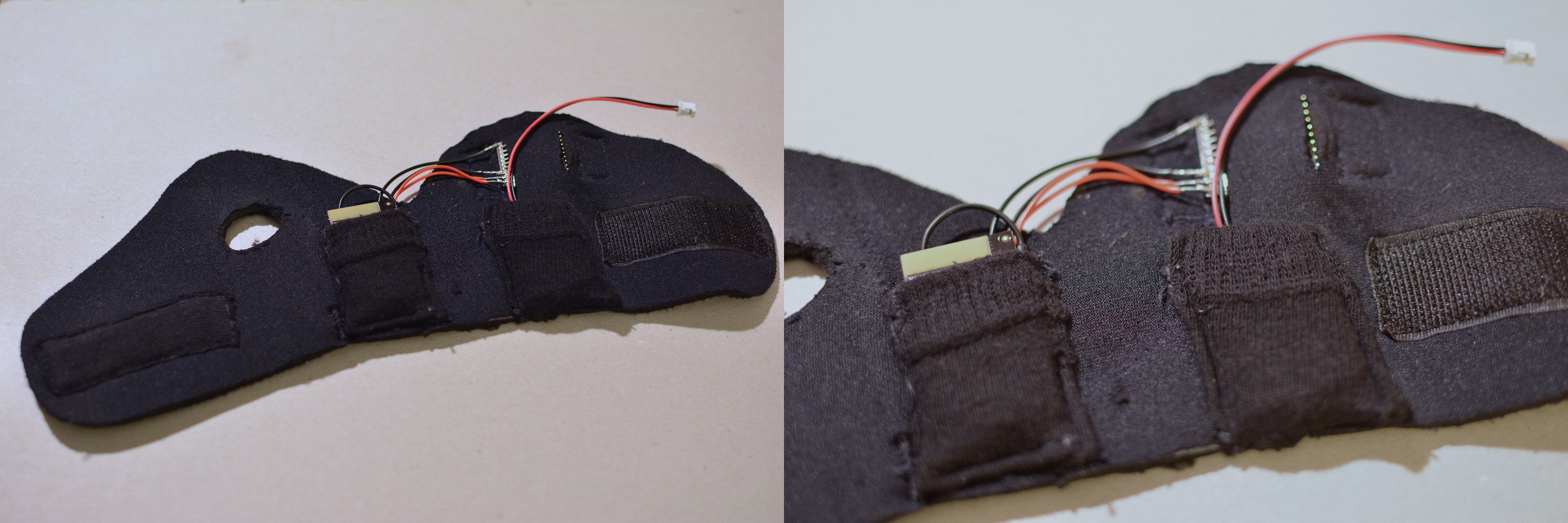
First of all, we're going to sew a pocket for the Curie Nano onto the glove. The most important point here is to place the board in a way that allows tight coupling of the sensor to your hands movement. We found the best place for this is the area between the wrist and the lower part of the palm, specifically the side opposite of the thumb. With a elastic piece of textile, cut out a piece a little larger than the Cure Nano, and sew it as a pocket to the glove. You will want to be able to take out the board to reprogram it or to modify / fix it. Also take care that you can lead the cables (soldered to the board in Step 4) out of the pocket.
![The Curie Nano pocket The Curie Nano pocket]()
The Curie Nano pocket XBee & socket header
In the last step we soldered the wires to the XBee header, now it's time to build the XBee module into the glove. The constrainst are:
- The XBee is placed on the outside of the glove.
- The XBee needs to be removable for programming.
- The cables are lead inside the glove.
- The socket-header stays accessible.
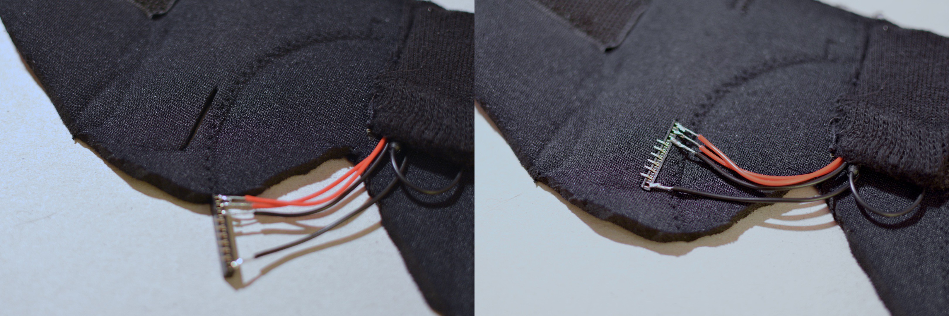
Cut a slot into the glove the length of the socket header. Place the XBee pins into the slot to measure the distance to where you're going to cut the next slot for the other row of pins. Remove the XBee.
![The slot for the socket header The slot for the socket header]()
The slot for the socket header ![Socket header on the outside Socket header on the outside]()
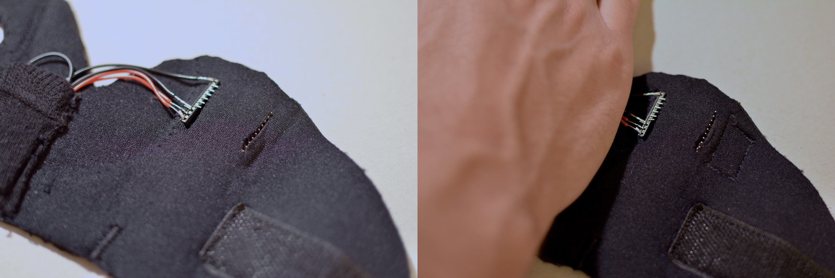
...the socket header & XBee on the outside of the glove Decide in which direction you want to place the socket header, in our case pin 1 is on the bottom, pin 10 on the top. Place the socket header into the slot in the direction you chose and carefully bend the pins so they lie flat on the inner surface of the glove. You can now plug in the XBee on the outer surface of the glove.
![Location in the glove Location in the glove]()
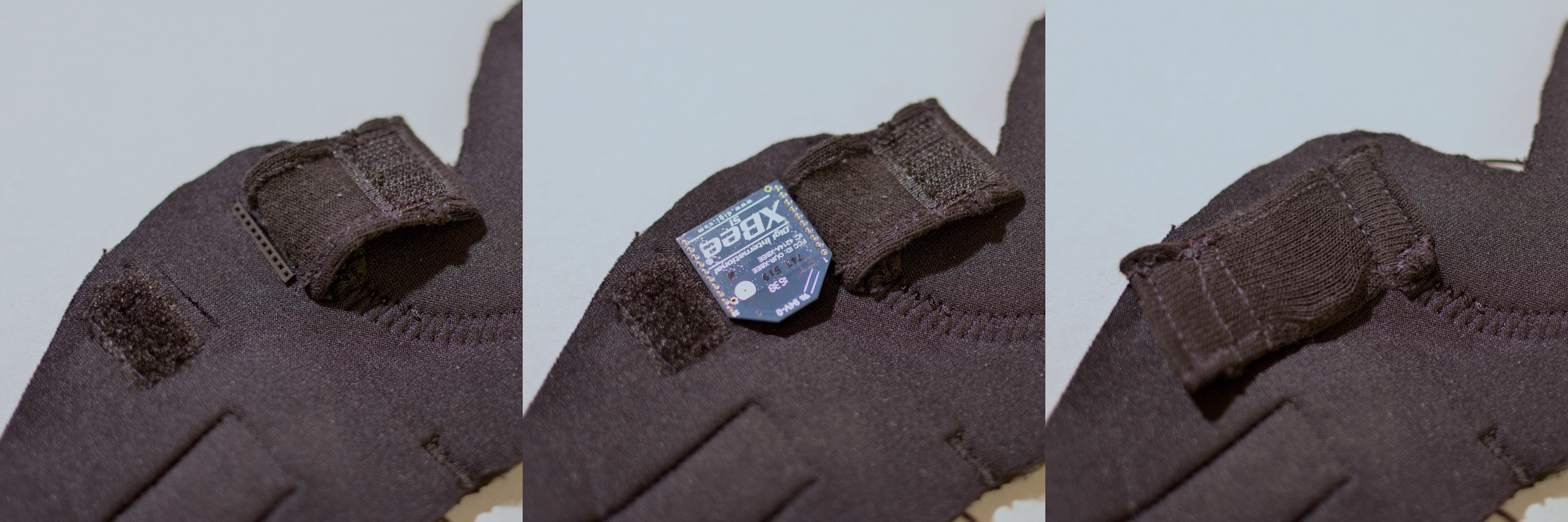
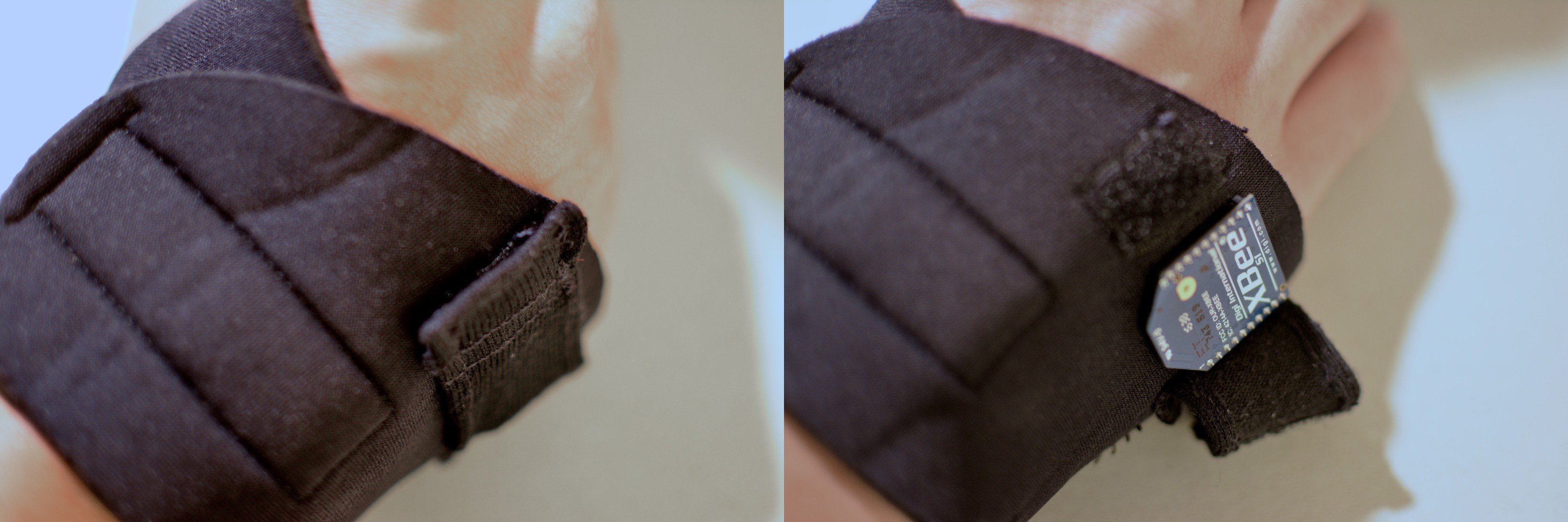
Placement of the XBee relative to the hand If this all works out, remove the hardware again. To protect the part (also to conceal them), use pieces of textile and velcro to build covers for the XBee (covering the cabling will follow a bit later). We suggest using velcro to easily open and close the compartment.
![The outer XBee cover The outer XBee cover]()
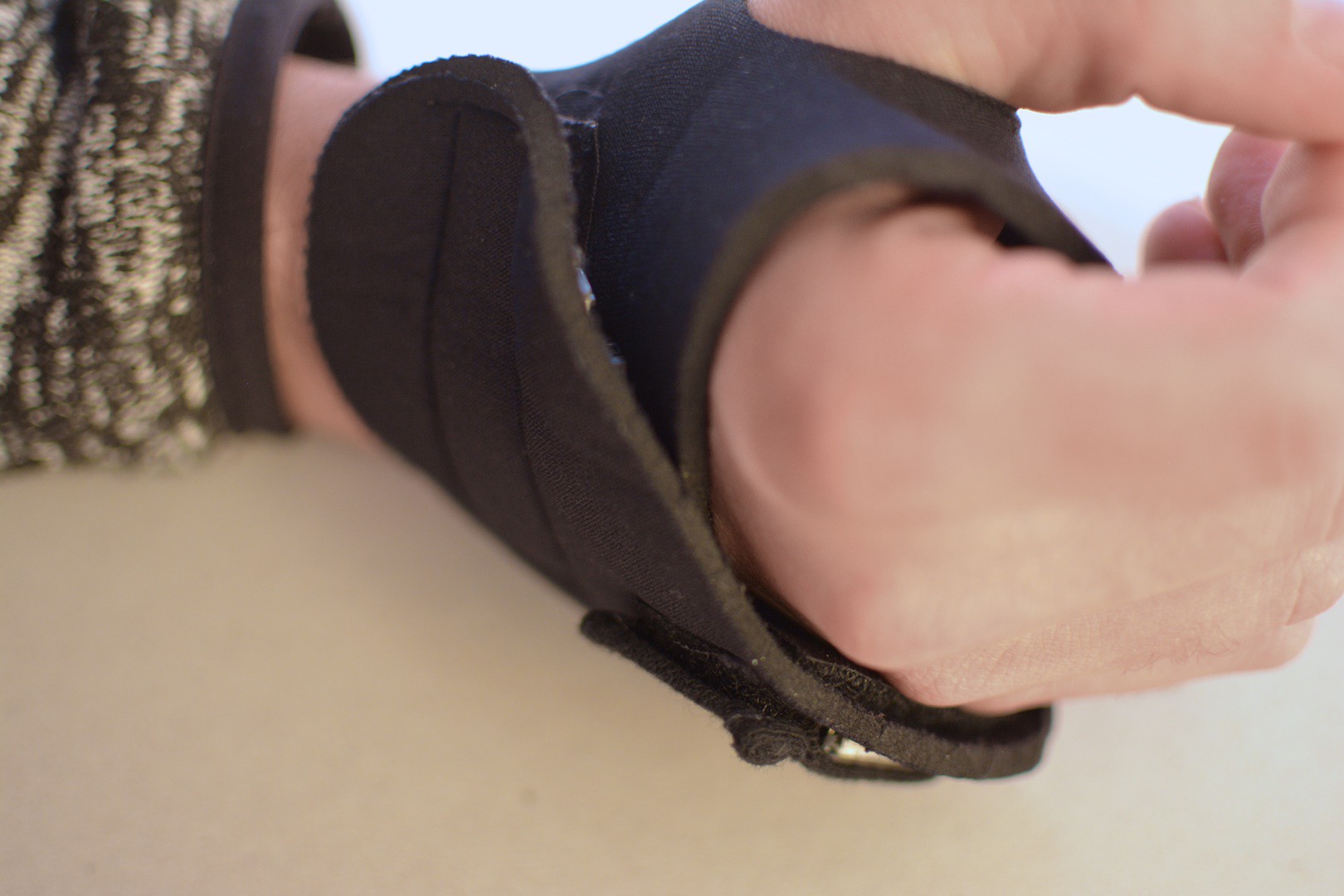
The outer XBee cover ![XBee, worn on the glove XBee, worn on the glove]()
XBee, worn on the glove Battery & power switch
For the battery you sew another pocket. This time, we suggest placing the pocket so it rests on the back of you hand while wearing the glove. As with the Curie Nano, make sure the pocket holds the battery safely in place while still allowing to remove it (i.e. for charging)![Placement of the battery pocket Placement of the battery pocket]()
Placement of the battery pocket The switch will be placed in a location that you can reach, to turn it on and off while wearing. You can sew the power switch through the unused soldering holes (GND and +), and around the board itself.![]()
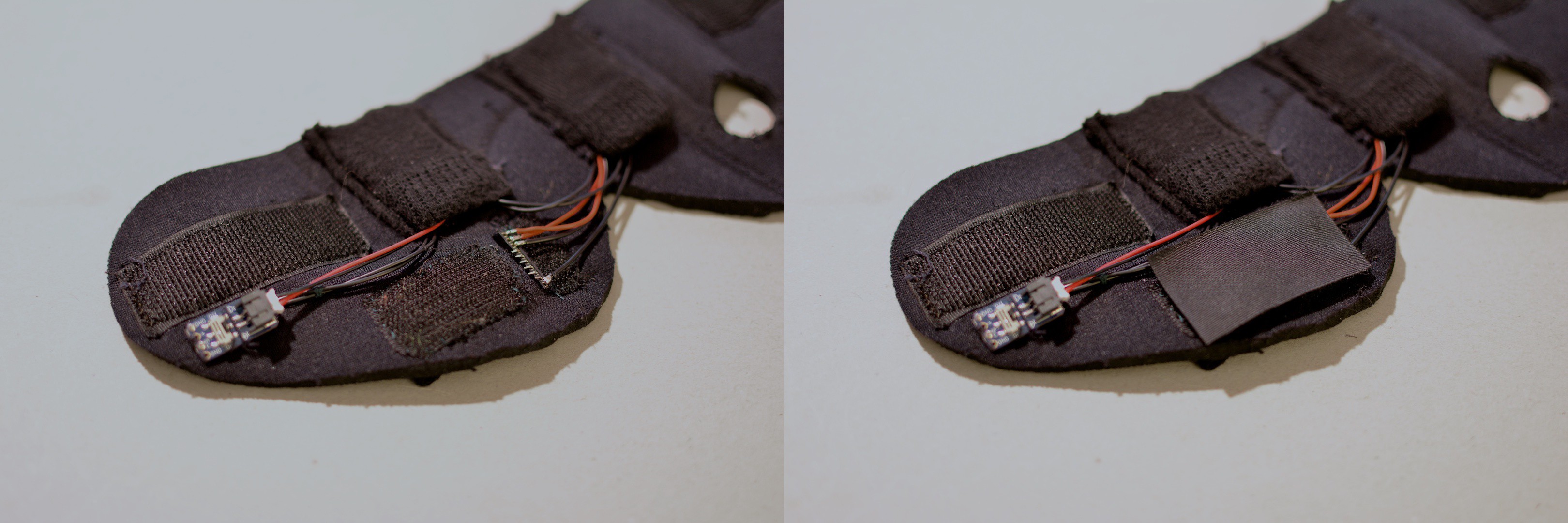
The inner XBee cover
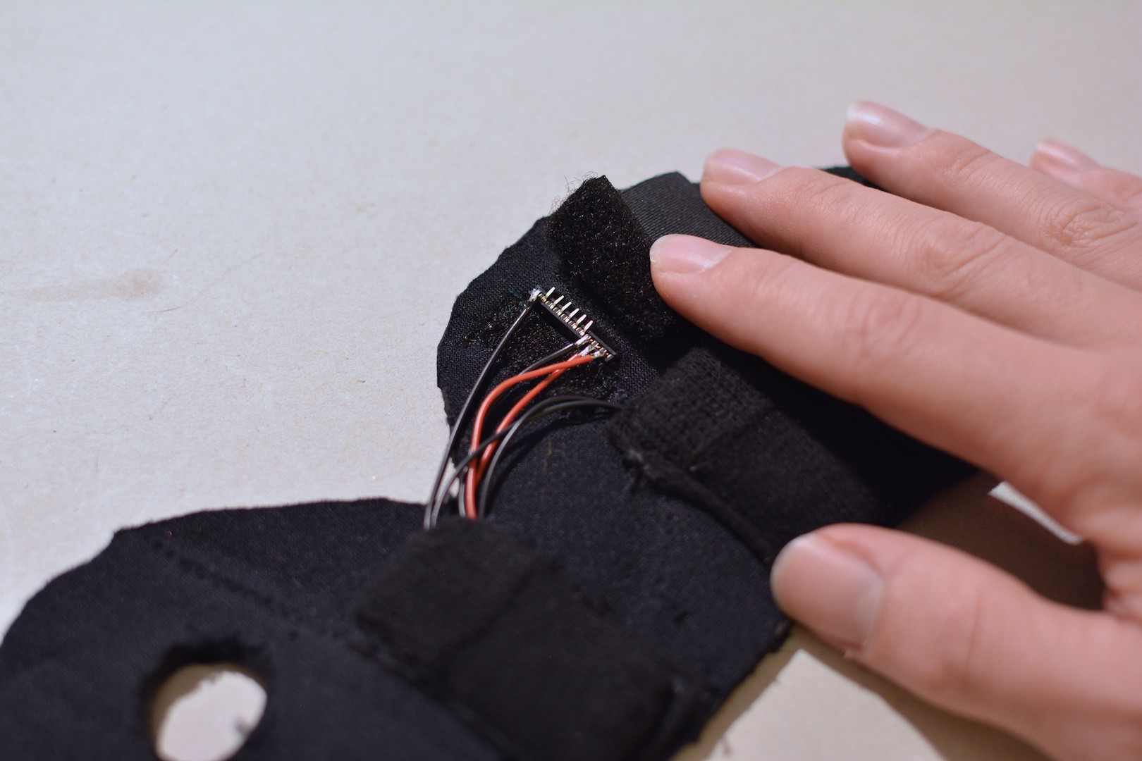
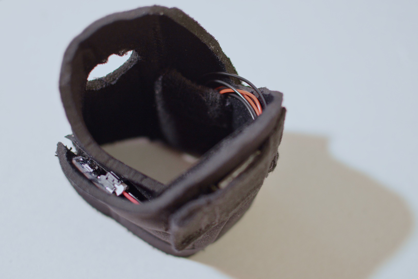
Now that all cables are in place, you can plug the battery in. Now it makes sense to add some cover for the XBee sockets headers on the inside of the glove, while aligning the cabling alongside or under that cover. Again, we suggest to use velcro so you can easily remove the cover later on.![The inner XBee cover The inner XBee cover]()
The inner XBee cover ![]()
The glove is ready!
Wear it on, turn it on. You can now explore the Pure data sound modules :-) Enjoy!![]()
![]()
-
6Assemble the sound module
Get the parts ready
In this step you're going to build the standalone sound module that, together with the sensor unit in the glove, forms the whole of the Gesture-based Performance System (GePS). You need the following parts and environment:
- The Raspberry Pi 3 Model B+
- A microSD card (and probably a microSD to SD adapter)
- A power supply powerful enough for the Raspberry Pi (we use the official power supply)
- The Pisound audio interface by blokas.io (comes with 2 knobs, 8 screws and 4 spacers)
- Your Laptop and the Raspberry Pi in the same network (the latter connected via ethernet cable)
- A pair of headphones (with 1/4" plug) or a speaker system with the same connector.
- The receiver (used in Step 4): The XBee, XBee USB Adapter and a micro USB cable
- The GePS sensor unit
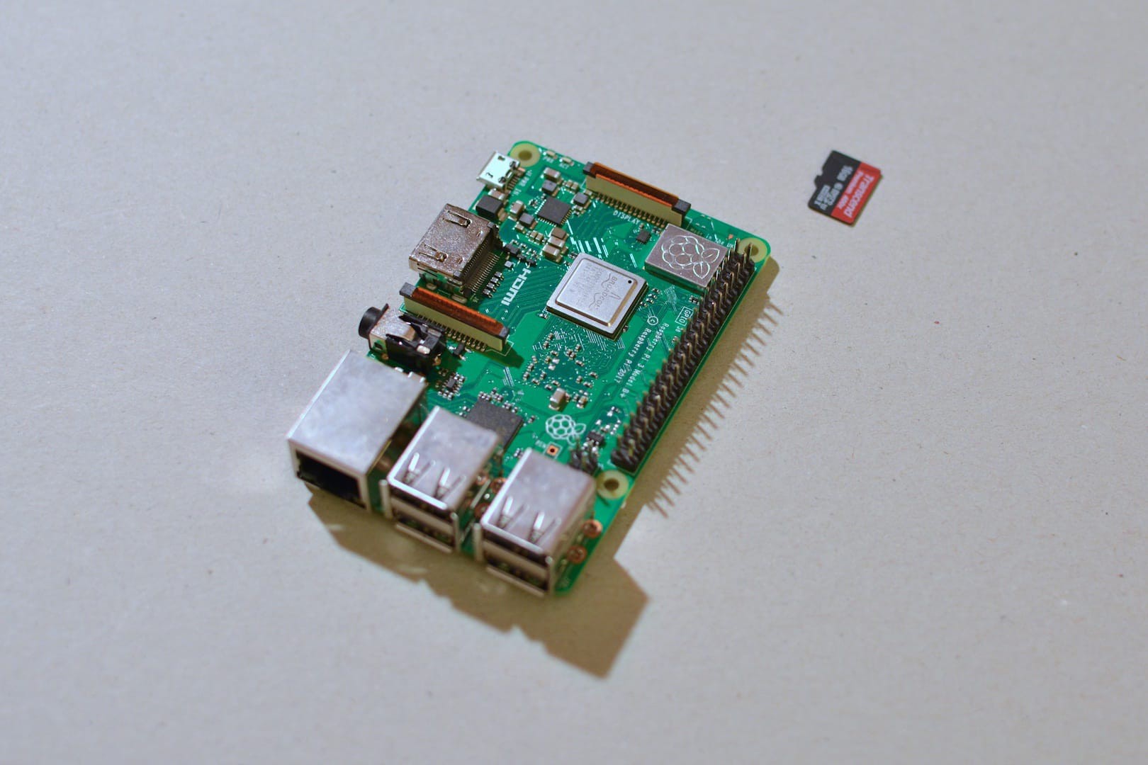
![The Raspberry Pi 3 Model B+ and a 8GB microSD card The Raspberry Pi 3 Model B+ and a 8GB microSD card]()
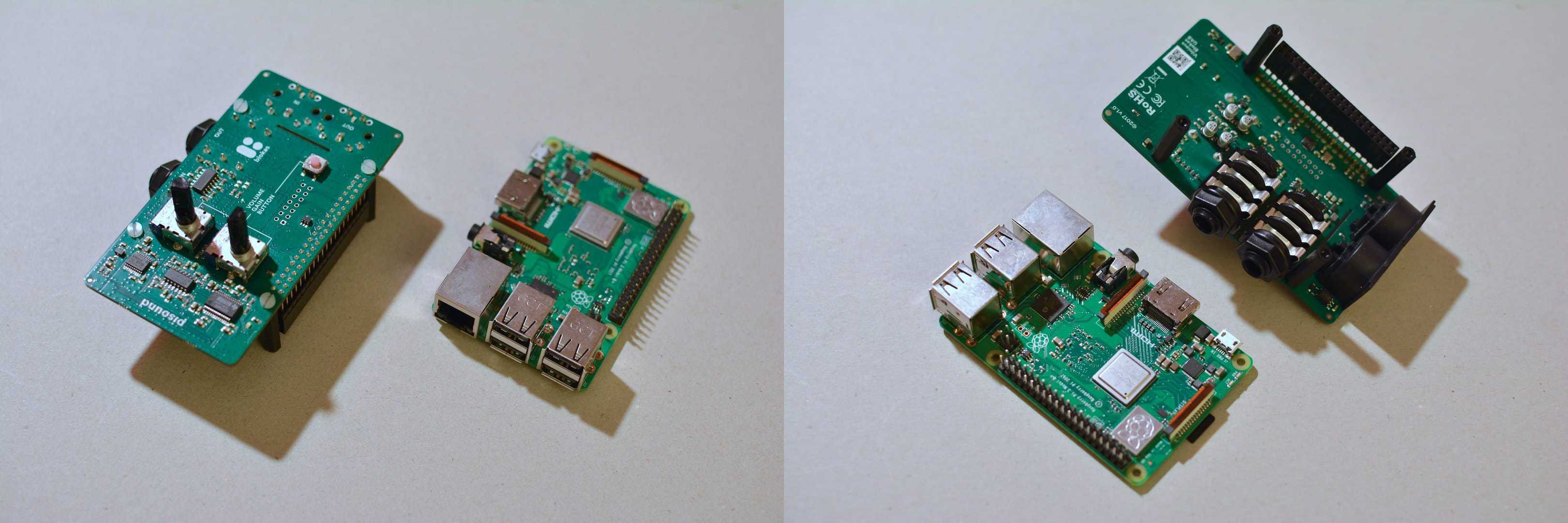
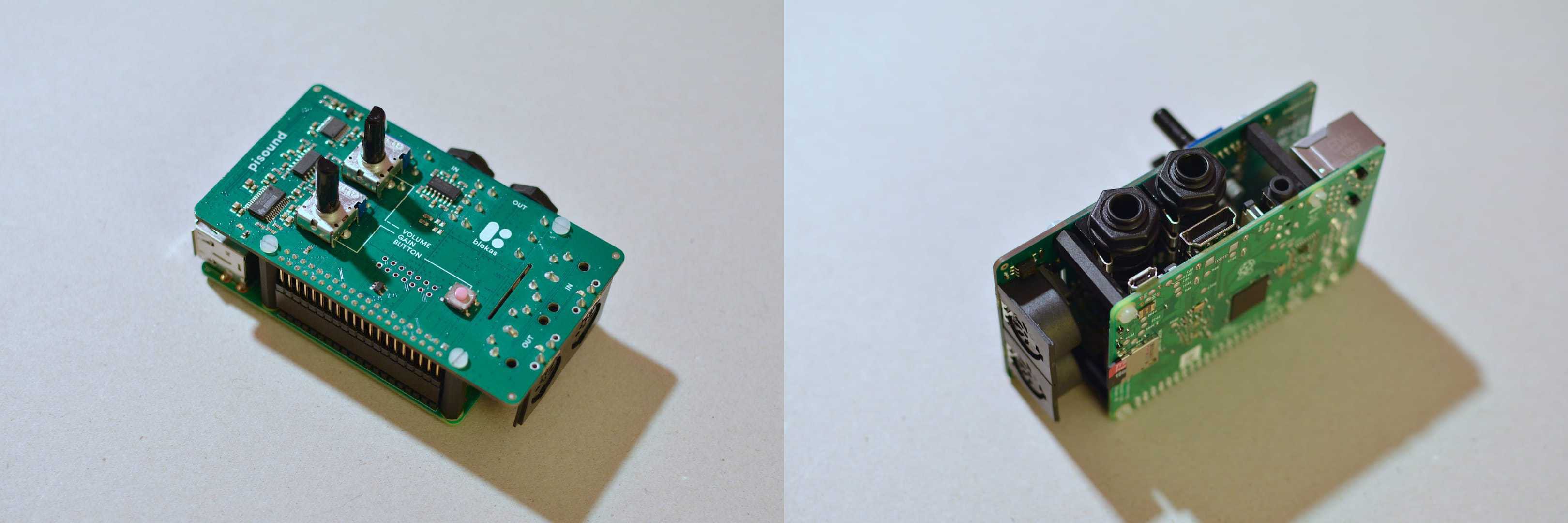
The Raspberry Pi 3 Model B+ and a microSD card The assembly step is pretty straight forward: Screw the 4 spacers to the Raspberry Pi mounting holes (8 screws and 4 spacers come with the pisound package). Carefully plug the GPIO socket header of the pisound onto the GPIO pin headers of the Raspberry Pi. Screw the pisound to the spacers to keep in place. That's it for assembly. For more information check out the documentation on blokas.io.
![]()
![]()
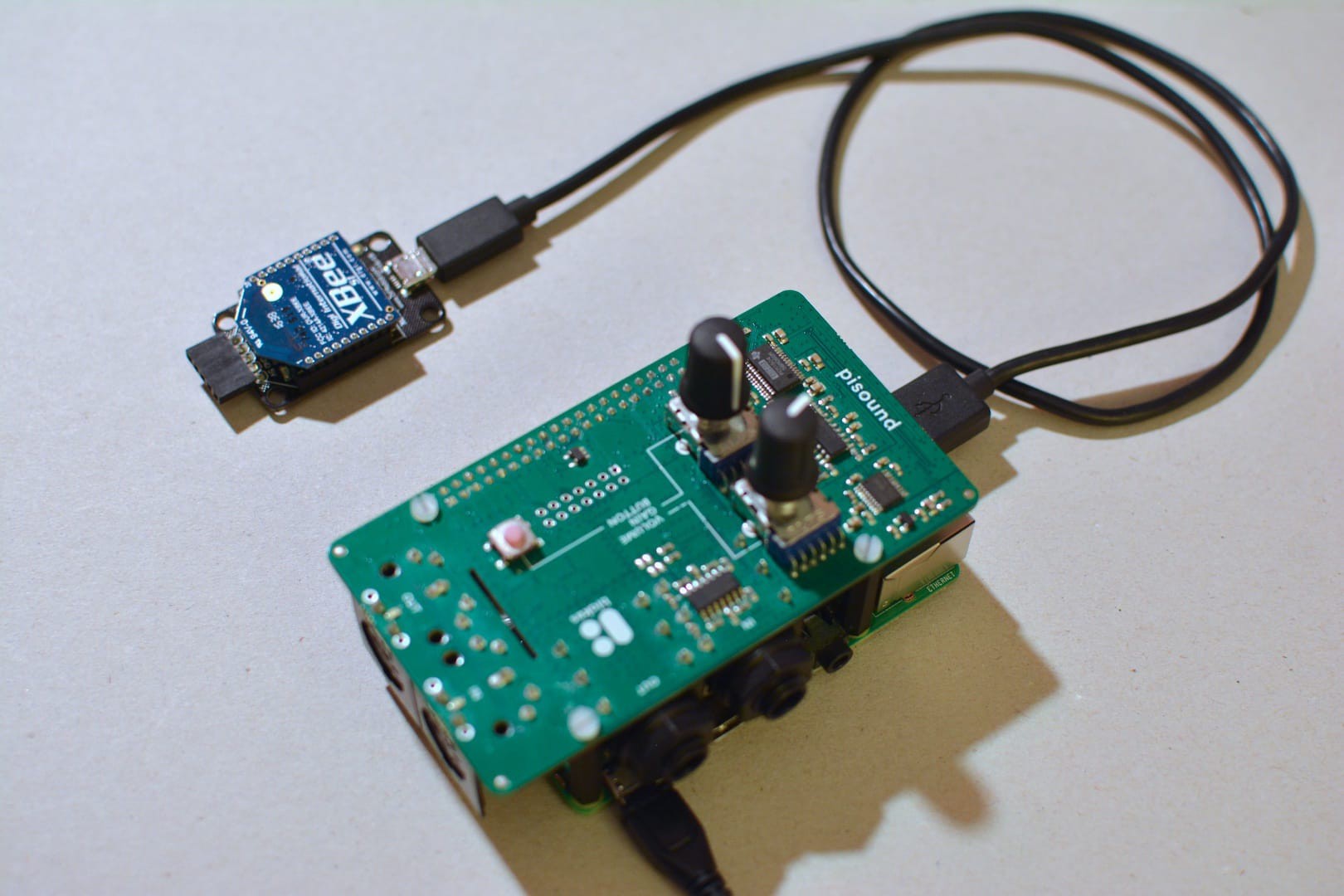
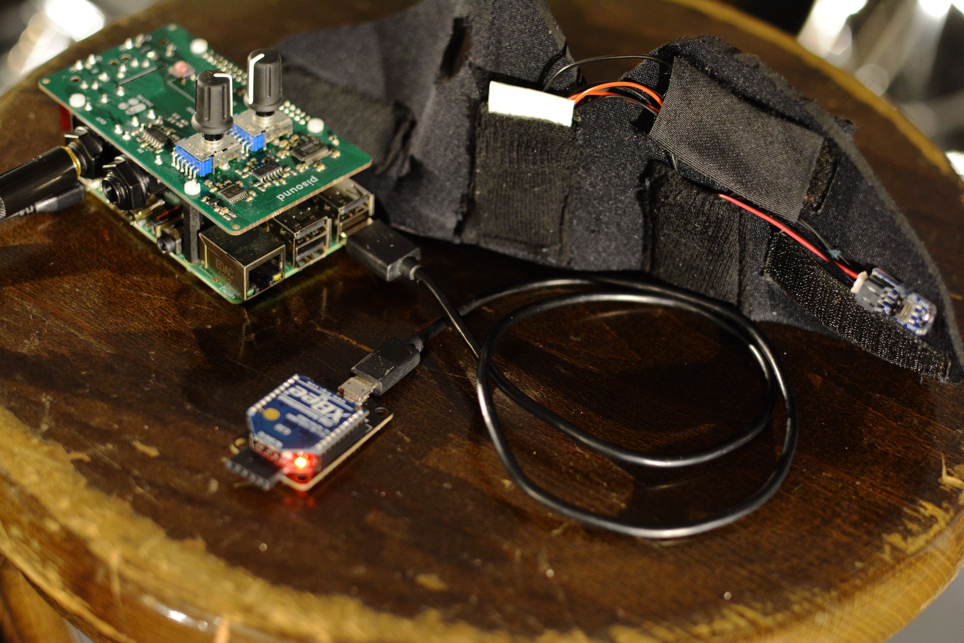
You may now connect the receiver (the second XBee, plugged to the XBee USB Adapter) to one of the Raspberry Pis USB port, using a micro USB cable.
![Raspberry Pi with Pisound, knobs and receiver XBee connected Raspberry Pi with Pisound, knobs and receiver XBee connected]()
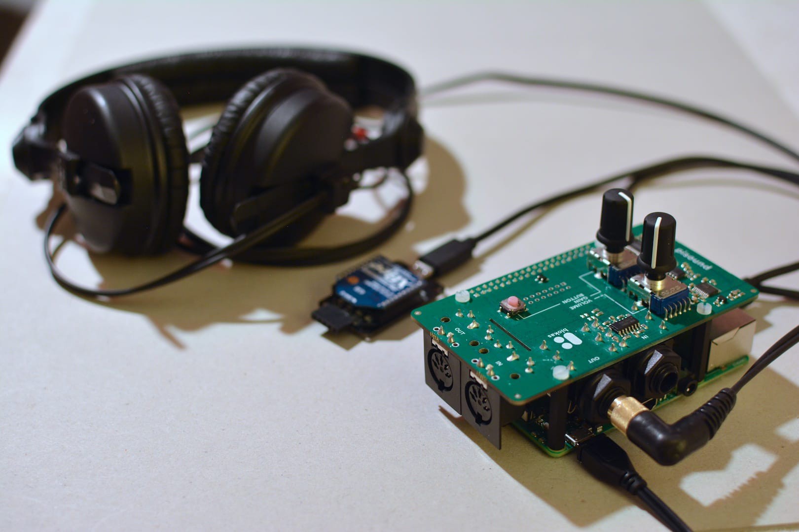
Raspberry Pi with Pisound, knobs and receiver XBee connected If you like, you can already add the knobs to the potentiometers on top of the pi sound. After connecting headphones or speaker system to the audio out of the pisound (you need a 1/4" TRS jack) the hardware part is done for now. Do not power up just yet, you will have to install an operating system and the GePS distribution first.
![]()
-
7Provisioning the Raspberry Pi
Next, you're going to get the SD card ready for booting the operating system on the Raspberry Pi. This begins with copying the official raspbian lite image to the SD card. This is a process that can be done in many ways, and it slightly differs depending on what operating system you use. The documentation on raspberrypi.org is excellent! And the following instruction is a short form of the advanced instructions for macOS.
For this project we will use raspbian light, the official Debian based distribution without graphical user interface. A GUI is not necessary, as the sensor unit is our way of interacting with the sound module. The whole provisioning/installation process will therefore also be without GUI, mostly using a remote login via SSH.
Fire up your favourite terminal emulator on you laptop and let's go! Create a directory (provisioning) holding the files used in the following instructions, download and unpack the latest raspbian light image:
mkdir provisioning && cd $_
curl -LO https://downloads.raspberrypi.org/raspbian_lite_latest
unzip raspbian_lite_latest
rm raspbian_lite_latest
With the SD card plugged into your laptop check for the BSD drive name with diskutil list. It's usually a good idea to identify it by it's capacity.
Then unmount the volume and copy the image to the device (this will take a while, check with Ctrl-T):
diskutil unmountDisk disk2
sudo dd bs=1m if=2018-10-09-raspbian-stretch-lite.img of=/dev/rdisk2 conv=sync
Once this is done, you can check diskutil list, there should be two partitions: boot and Linux. We will need to make a small change on the boot partition, so it needs to be mounted:
diskutil mountDisk disk2s1
touch /Volumes/boot/ssh
diskutil unmountDisk disk2
This adds an empty file named `ssh` in the root of the boot partition. Doing so will enable the SSH server on raspbian, allowing you to log in remotely.
Booting raspbian and login remotely
Plug the SD-Card into the Raspberry Pi and power it up. Connect the Raspberry Pi to your network through an ethernet cable. The network interface (NIC) of the Raspberry Pi will get an IP address assigned, given your network is configured by a DHCP-server.
You can now either check the address table of the DHCP-server or scan for the Raspberry Pi in your network. Run nmap (install with your favourite package manager) in ping mode to find the IP-address of the Raspberry Pi. In the following example the address of the network (to which your laptop and Raspberry Pi is connected) is 192.168.1.0. nmap is run with super-user privileges to enable MAC address and therefore NIC Vendor resolution, in ping-scan mode (-sP) over all addresses of the network (/24), assuming your network has a 24bit netmask.
sudo nmap -sP 192.168.1.0/24You can recognise the ethernet port (NIC) of the Raspberry Pi by the vendor part of its MAC address, which is pointing to "Raspberry Pi Foundation". Take a note of the associated IP address (192.168.1.181 in the following examples).
Nmap scan report for 192.168.1.181
Host is up (0.015s latency).
MAC Address: B8:27:EB:66:47:A5 (Raspberry Pi Foundation)
By now you should be able to log in using SSH. Test it and log out again. The default password of the user pi is raspberry
ssh pi@192.168.1.181Configure SSH public key authentication
To conveniently logging in without typing the password you can generate a public/private SSH key pair and copy that key to the Raspberry Pi. This will also ease the use of Ansible to set up the operating system.
ssh-keygen -b 4096 -t ed25519 -f ~/.ssh/rpi-provisioning \ -C "raspberrypi-provisioning-$(gdate -Iseconds)" ssh-copy-id -i ~/.ssh/rpi-provisioning pi@192.168.1.181- when prompted, type "yes" (if you believe that this IP address still belongs to your Raspberry Pi)
- when prompted, type the default password of the raspbian pi user: raspberry
The public key part of the generated key-pair will now be copied to the raspberry, in the future you can log in (only) from your computer without entering a password. Try it out:
ssh -i ~/.ssh/rpi-provisioning pi@192.168.1.181Run the Ansible playbook
In the setup directory of the GePS github repository we prepared an Ansible playbook to take over the provisioning / installation of the Raspberry Pi (we use Ansible to automate the management a number of Raspberry Pi). To run this playbook you need to have Ansible installed on your computer, use your favourite package manager to install it (i.e. brew install ansible).
cd setup
ansible-playbook --key-file ~/.ssh/rpi-provisioning \
    -u pi -i 192.168.88.181, geps-raspbian-playbook.yml
The playbook automates the following tasks:
- Add the pisound package repository
- Upgrade raspbian
- Install software dependencies for building Pure data, and the pisound packages
- Disable unnecessary services
- Configure the default sound card (pisound)
- Build Pure data and dependencies from sources
- Install the GePS package
- Enable starting the GePS sound module when booting the Raspberry Pi
We chose to build Pure data and the dependencies (externals) from sources to get latest and greatest versions (Pure data release 0.49 as the time of this writing), which are not available through the standard repositories.
Upon completion of the Ansible playbook, the Raspberry Pi - GePS sound module is ready to go! Turn on the glove sensor unit and start exploring the sounds!
![]()
 Zed Cat


Discussions
Become a Hackaday.io Member
Create an account to leave a comment. Already have an account? Log In.