-
1Schematic and layout designing
Schematic and layout designing is done on the Eagle PCB design software. The design is made taken into consideration of the different requirements of the ICs used in the board. The important design aspect to be taken care of is to choose the value of VCAP of the microcontroller. The value of the VCAP is to be choosen between 470nF and 1uF. If the value is not choosed carefully then the whole design wont work. The schematic and the layout files are uploaded in the files section.
-
2PCB fabrication and soldering of the components
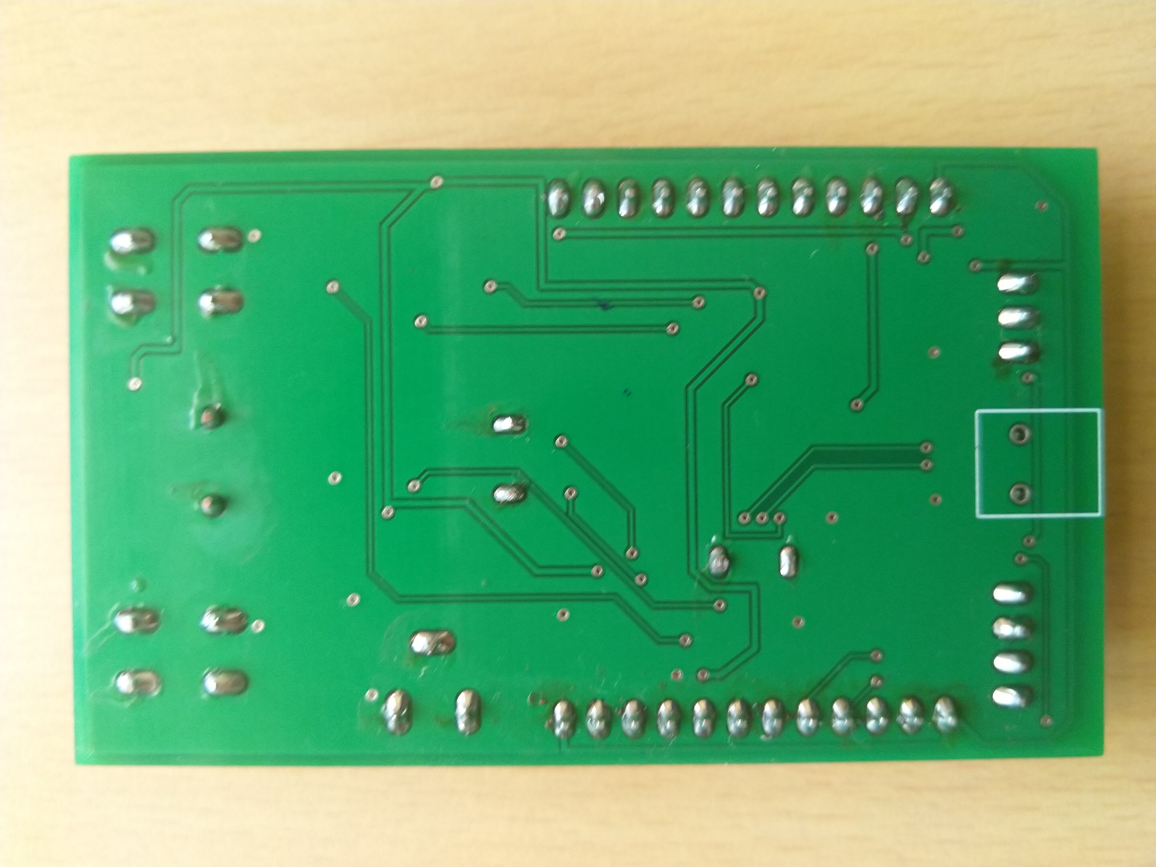
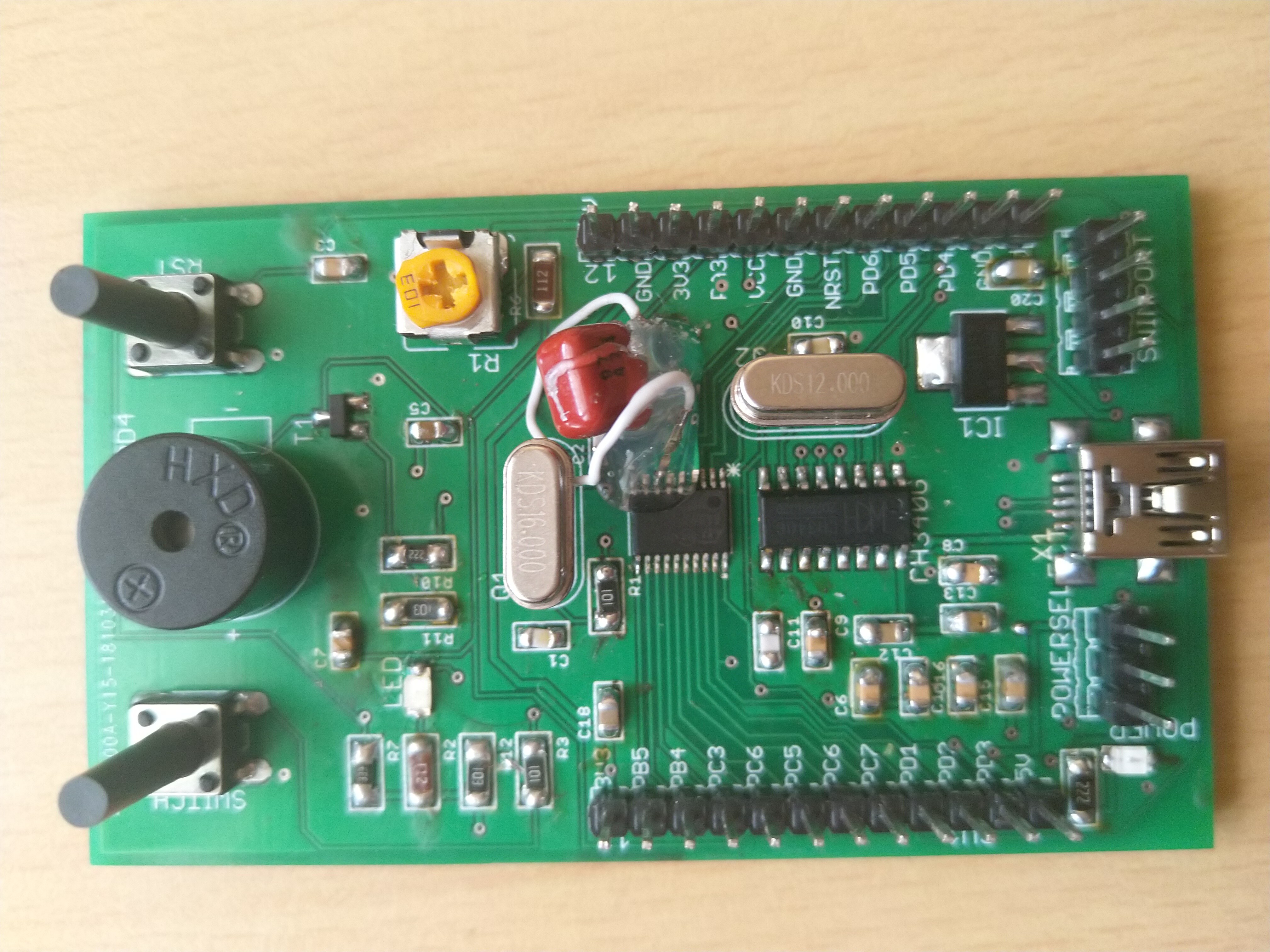
The layout is checked and each layer is verified using Gerbview software. Then it is given for the fabrication. After the PCB is received, the components are soldered in the main PCB and are checked for any short connections.
![]()
![]()
-
3Testing of development board and working of the peripherals
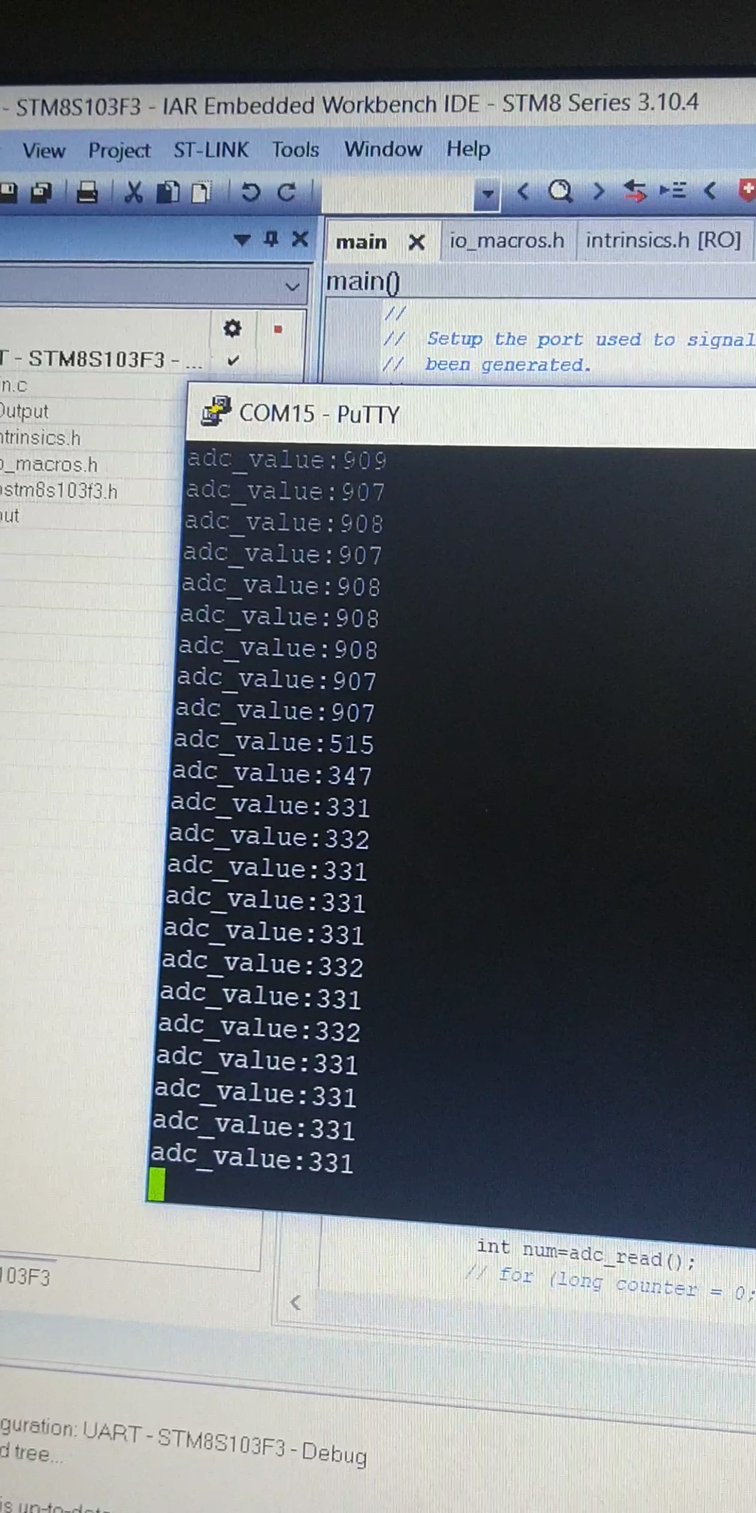
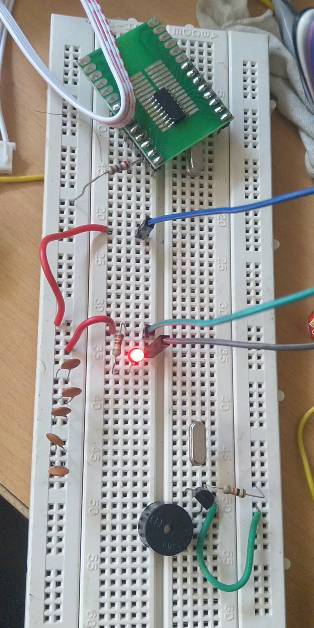
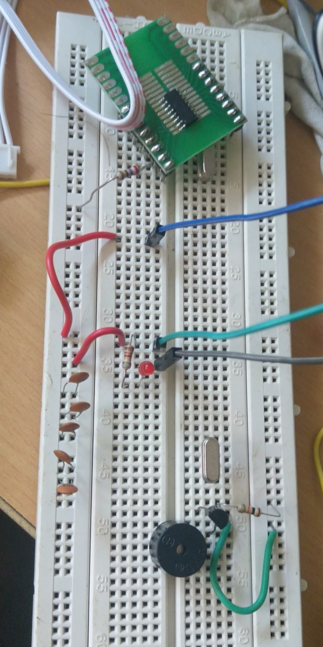
The development board and the working of the peripherals is tested using the codes which are uploaded. The programmer used is ST-Link V2 and is programmed using the SWIM port . The compiler used for the codes is IAR Embedded Workbench.
![]()
![]()
![]()
STM8S Development Board
A project which aims to build a development board for STM8S003F3P6 (20 pin SMD) microcontroller.
Discussions
Become a Hackaday.io Member
Create an account to leave a comment. Already have an account? Log In.