-
1▇▇▇▇ A Simple State Machine ▇▇▇▇
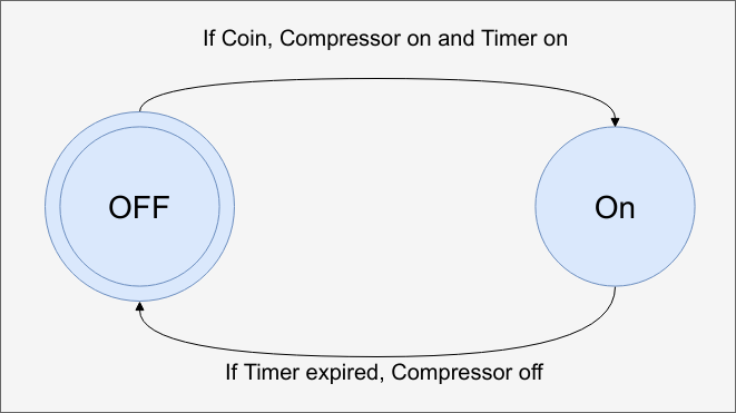
This diagram shows what could be one of the simplest state machines possible.
![]()
It operates a hypothetical air machine at a gas station. You insert a quarter and the air compressor turns on for a fixed amount of time. When the timer runs out, the compressor goes off and they system waits for more money.
This is very simple, of course, but it illustrates a few things. The blue circles are states and the double circle indicates the state the system starts in. In some diagrams, you'll see an arrow coming from nowhere labeled reset or some other way of identifying the initial state.
The lines are transitions. The labels on them should tell you why you'd move from one state to another and what outputs occur on those transitions. There's some variations possible on this and we'll talk about them later, but this is basically it.
Coding this in Verilog would be pretty simple:
`timescale 1s/100ms
module airpressure(input clk, input reset, input coin, output compressor);

   reg state; // 1 = on, 0 = off

   reg gotcoin;
   reg [6:0] timer;
   localparam timerinit=60;  // must fit in timer!
   wire nextstate;

// logic for output
   assign compressor=state;
// logic for next state
   assign nextstate=state?timer!=0:gotcoin;

  // Manage state and timer (for simplicity,
  // assuming clock is every second and that's
  // sufficient for the coin slot
    always @(posedge clk)

      if (reset)  // initial conditions
          begin state<=0;
            gotcoin<=1'b0;
            timer<=0;
          end

       else
           begin
               state<=nextstate;
               if (nextstate) timer<=timerinit;
               if (timer!=0) timer<=timer-1;
               gotcoin<=coin;
          end

endmodule
Of course, you could argue that an SR flip flop could do the same job and you'd be right. But this framework will allow us to build more complicated machines. For example, what if you wanted to change the price and allow more types of coins? Or let the user add coins to extend the time?
Here's part of the simulation:
![]()
Note that I made the simplifying assumption that the clock was one second and the coin acceptor would hold its output that long. In real life, you'd need to implement the timer differently, I'm sure.
Don't forget you can run all of this yourself in EDA Playground. Consider changing the code to require two quarters instead of one. What would have to change?
-
2▇▇▇▇ Adding Complexity ▇▇▇▇
Instead of two quarters, suppose we just want to let the machine take nickles (5 cents), dimes (10 cents), and quarters (25 cents). The price is still 25 cents, but you don't have to have a quarter. If you put too much money in, we'll just keep it and dispense the same amount of air.
Take a minute and try to sketch the state diagram for that before you proceed. Although in this case, you could have a very simple state machine that keeps track of the total, try thinking about how to not store the sum but remember the current value as part of the machine's state.
Too Simple
You could, of course, have a state for every possible sequence of coins:
- 25 cents
- 10 cents, 10 cents, 5 cents
- 5 cents, 5 cents, 5 cents, 5 cents, 5 cents
- ... etc.
This gets you a lot of states fast. Keep in mind, that the second line (10/10/5) could also be 5/10/10 or 10/5/10 so the number of states will grow fast.
Better
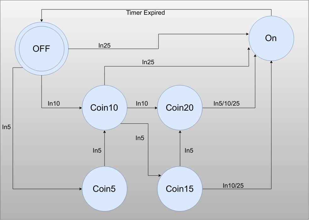
The trick is to gather up equivalent states -- something we will talk a little bit about in a future section on state machine optimization. If you imagine the entire sea of states that would make up the above list, you should realize that every state that represents 20 cents is exactly the same as far as outputs and transistions go. So it makes sense you can merge them into one single state. Since this machine is pretty simple we can do that just by thinking about it and you should wind up with something like this:
![]()
To simplify things, I am not showing the outputs. They are the same as before. The On state turns on the compressor and leaving the On state turns the compressor back off. The Inxx (like In5) means the input of a coin with that value. In10/25 means either a 10 cent or 25 cent coin detection.
Heuristics
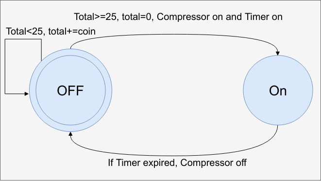
As I mentioned, you could do better than this by applying some domain knowledge. We already did this a bit by supposing we have a timer. That is, we didn't have a state for 59 seconds left, 58 seconds left, etc. You could apply this same logic to keeping count of the coins in a separate register. Your state machine would then look like this:
![]()
As a practical matter, this may be the best implementation, but it doesn't show off the state machine very well and real projects will have many more states. But like most design problems, there are many ways to solve this and there are probably many more, too.
-
3▇▇▇▇ State Implementation ▇▇▇▇
When creating a state machine, there are two things to consider: How to represent the state you are currently in is the most obvious one. This may seem like a trivial concern, but as you'll see, there is more to it than meets the eye.
The second decision is how you translate your logic into a state machine. There are many possible ways, of course, but most people prefer to use the following methodology:
- Use a clocked always block to store the current state.
- Create one or more pieces of combinatorial logic to compute the output for the current state.
- Create one or more pieces of combinatorial logic to compute the output for the next state.
Represent!
The machines we have looked at so far have a pretty small number of states. So there's no real problem representing the states as normal binary numbers. For example, a parity checker might have an idle state (0), an odd state (1), and an even state (2). You use two flip flops and you are "wasting" one state (since 3 is an illegal state). But that's not a big deal.
However, any time you want to decode the state, you have to examine both state variables. Again, for two that's not a big deal, but what if you had, say 100 states in 8 bits? Or 1000 states in 10? Finding state 821 will take a few inverters and an AND gate. Of course, storing 1000 states in 10 bits is relatively compact, too.
But what if you don't care about compactness. You care about speed. Probably the fastest method to represent state is the so-called "one hot" method. In the case of the parity machine we would have three binary bits for the state. Idle might be 001, odd would be 010, and even would be 100. At all times, there is only one flip flop set -- which makes sense if you think about the name one-hot.
Now it is easy to detect a particular state by examining a single bit. So it is fast and easy, what's the downside? You'll need to pay attention to reset because 000 isn't a legitimate state. You sometimes see people use a "modified one-hot" where 000 is the initial state, but if you ever need to decode that state, you lose the advantage.
Space is another problem. If you really had 1000 states (and, yes, that's probably bigger than you should have) then you'd need 1000 bits of state. Another more subtle problem is reliability. If you want to detect an illegal state, you'll need some sort of gating arrangement that asserts only if more than one state bit asserts. That gets complicated fast with too many bits.
Still, one-hot is often a great choice for state encoding, and you see it used frequently. With negative logic you sometimes see "one cold" encoding which is the same as one hot, but the active state is zero.
Gray Codes
Speaking of reliability, gray code encoding is also possible in some cases. This is similar to the numeric representation except the bit patterns are selected so that only one bit changes per state transition. For example, this wasn't true with the parity machine we mentioned before. In binary, the states were 00, 01 and 10. If you can go from 01 to 10 or vice versa, that's two bit flips. We say the hamming distance between those states is two.
If we made the parity machine gray, it would turn into a one hot. But consider a different example. Let's say we have a state machine that will count the number of button pushes from 1 to 3. A simple encoding would be two binary bits: 00, 01, 10, and 11 where 00 is the idle state. But, again, the transition between 01 and 10, as well as 11 and 00 requires two bit flips. With a gray code, the states might be: 00 01 11 10. Now each transition only takes one bit flip.
There are other encodings like Johnson and O'Brien that seek to minimize bit changes between adjacent states. These schemes can be useful when you want to use combinatorial logic to detect state changes or you are worried about power consumption.
It isn't always possible to build a gray or similar sequence without some work. For example, consider the 00, 01, 11, 10 sequence mentioned above. That's fine if the states go from one to another in sequence. But what if state 00 could go to state 11? You'd need to rearrange the code or use more bits. This is a big problem if you add or change transitions in the middle of the design.
Coding Style
Let's consider a state machine to figure out if the sum of positive numbers is even or odd. It doesn't matter how many bits the numbers are, because all we need to do is look at the last bit of any number to know if it is even or odd. An even number plus an even number is even. An odd number plus an odd number is even. And an even number plus an odd number stays odd.
We will need three states: idle, odd, and even and let's use one hot encoding, just for practice. It is handy to use localparam to name the states so:
module odd_even_sum_detect(input clk, input reset, input bit0,
        output oddled, output evenled);

   reg [2:0] state;
   reg inbit;
   localparam idle=3'b001;
   localparam odd=3'b010;
   localparam even=3'b100;
Of course, this is a simple example, so you might have even had:
reg idle, odd, even;
This gets clumsy, though, when you need to reset things or examine several states at once.
Remember, we said it is customary to put the state machine into at least three parts. The first part is state management. We'll also use this as an excuse to save the input bit so if it changes externally, we won't care.
   reg [2:0] nextstate;
    always @(posedge clk)
        if (reset)
          begin
            state<=idle;
            inbit=1'b0;
          end
       else
           begin
               state<=nextstate;
               inbit<=bit0;
          end
Obviously, the trick now is to compute nextstate. This could be done with an assign or with a combinatorial always block. I'll use the always block:
    always @(*)
      begin
          if (state==odd) nextstate=inbit?even:odd;
          else nextstate=inbit?odd:even;
     end
There are a few interesting things to notice here. First, the idle state is zero so it is intrinsically even. The else branch catches both cases. That's the second point, though. You must assign nextstate in all cases so you don't infer a latch. If you fail to do so, the synthesizer will assume you want to keep the next state, but not with a flip flop and you will get a latch. This is usually undesirable.
Because this is combinatorial, you can use = instead of <= and the last assignment is going to "win." So you could, for example, assign something at the top of block as a default or, if using a case statement, be sure to include a default case. In this example, even an illegal state (if one were possible) or an idle state would still get an assignment because we only check for odd and then do something for everything else.
You might also notice that if state is odd, nextstate is the inverse of inbit otherwise, it is inbit. So you could write this as:
nextstate=(state==odd)^inbit;
However, this is less intuitive and -- as we will talk about later -- the tools may even figure that out on our behalf.
That leaves one more piece to write. The output section which is, again, combinatorial. This time I'll use assign, but I could do another always @(*) if I wanted to.
   assign oddled=state==odd;
   assign evenled=state==even;
You hope your synthesizer would figure out that checking for all the bits is not necessary, but if it really checks for 010 and 100, that is kind of a waste. If you want to be more explicit, you could say:
   assign oddled=state[1];
   assign evenled=state[2];
Having a single clocked piece of code along with a combinatorial part to compute the next state and another to compute the output is known as the "3 process style" of state machine. However, some argue that this is more error prone. You can easily put everything in one place (the "1 process style"):
always @(posedge clk)

        if (reset)
          begin
            state<=idle;
          end
       else
           begin
               state<=state==odd?(bit0?even:odd):(bit0?odd:even);

               oddled<=state[1];

               evenled=state[2];
          end
For something this simple, it is fine. Note that I now don't need to latch inbit because that's done inherently when I store state. Of course, now oddled and evenled are reg types. I could have stayed with the assign and had a "2 process" state machine.
Which one is best? That's a hotly debated topic. In general, you should pick the style you are most comfortable with for the task at hand.
-
4▇▇▇▇ Decoding State ▇▇▇▇
Depending on how you store your state, there are a few things to consider. First, make sure you understand what states are legal. For example, in a one-hot machine, any state with multiple 1s (or no 1s) is illegal. Your reset should put the machine in a legal state. If you detect and correct illegal states or not will depend on your design. Sure, if everything works ok, and your design is solid you shouldn't get to an illegal state after reset. But, for example, in a radiation environment, perhaps a bit will flip at random. If you are worried about that or the consequence of bad operations are high, you might consider making sure you are always in a valid state.
Of course, if you are using a normal representation of state, you can simply code each illegal state to do some recovery action. For example, if you had a state machine with 2 bits and only 3 states, you might go ahead and code the 4th state to just push you back to an idle state, for example.
Generating Outputs
The main reason you'll want to know what state you are in is to produce some sort of output. There are two major strategies for doing this. The so-called Moore machine and the Mealy machine.
In a Moore machine, the outputs are purely a function of the state. If you get to state X, output Y occurs. Doesn't matter how you got there. In a Mealy machine, the output depends on the state, but also on the current input.
You can often tell which kind of machine a state diagram refers to because the output will be written after either the state (Moore) or input (Mealy) with a slash between them.
For example, if you see a state marked: Accept/Q=1 then that's most likely a Moore machine. If you see a transition -- an arrow between states -- marked RUN/Compressor=1 then that's a Mealy machine that changes state when RUN asserts and asserts Compressor as a byproduct.
Which is better? That depends on what you consider better. Mealy machines are often have fewer states since one state can serve multiple output situations. However, the Mealy machine's outputs don't completely rely on the clocked logic. This is both a plus and a minus. Mealy machines generally react nearly immediately to a change in inputs. A Moore machine usually has a clock cycle delay. However, that also means the outputs of a Mealy machine may glitch when you expect them to be stable. It is generally a bad idea to have the output of a mealy machine leave your circuit (say, to another module or an external output pin).
In general, we'll use Moore machines. Not only are they safer, but they also can implement some state machines that a Mealy machine can't.
One common thing to do is to create an output based on any of multiple states. This is a good example of where one hot encoding is useful compared to other schemes. Imagine two state machines that have an output that should be true if you are in S1, S2, or S3. The first state machine defines states as numbers 1, 2, and 3 respectively. The second state machine uses one hot encoding (1, 2, 4). The first machine might contain a line like this:
assign someoutput = state==S1 | state==S2 | state==S3;
The one hot machine could, however, write a simpler line:
assign someoutput = (state & (S1|S2|S3) != 0);
This isn't a big deal for three states, of course, but you can imagine that if you had a large number of states, the second is not only simpler to type, but more likely to generate a better result in synthesis. Although in the next section, you'll find out it may not make much difference with modern tools.
-
5▇▇▇▇ State Minimization (and Should You?) ▇▇▇▇
Remember the coin example from earlier? You could have a state that shows you had a dime and a nickle and another state for a nickle and a dime. But it was smarter to have one state for 15 cents. This is an example of state minimization.
If you were building a state machine from scratch, this would be very important as is selecting the right encoding. However, modern FPGA tools use inference and are likely to do what they think is right unless you use constraints or attributes to change that behavior.
You've already used inference. When you write:
always @(posedge clk) q<=d;
You are inferring a D flip flop. You could probably just as well have written something like:
dff ff1(.clk(clk),.d(d), .q(q)); // arguments depend on the vendor
Most synthesis tools can detect when you have a state machine and will make decisions about how to actually create it based on some heuristics built into the tool. To change those, you can use attributes.
What's an Attribute?
An attribute is a Verilog comment that uses (* and *) as delimiters. For example, if you want to tell the synthesis tool that your top module is "cpu" you could put in your Verilog:
module cpu(...) (* top *)
If you are using yosys, there are several attributes that can apply to a state machine or related logic.
- onehot - Mark wires as onehot state registers which allows certain optimizations.
- full_case - This marks a case statement as "full" -- that is, it provides an action for every possible input.
- parallel_case - This marks a case statement where only one item will match, allowing the synthesis to simplify the circuit.
You should probably not use the last two in general unless you have a very special case. Usually, the tools will identify if a case statement is full or parallel and make the correct adjustments. However, they are useful when using onehot states.
Let's take a machine with 3 onehot states 100 010 and 001. You might have code like this:
case ( {S2, S1, S0})
  3'b001: next<=3'b100;

  3'b010: next<=button?3'b001:3'b010;

  3'b100: next<=3'b010;

  endcase
We know that the combination of S2, S1, and S0 can only take on the values given. But as far as the synthesis tool can see, we just forgot to put lines in for things like 3'b111. The truth is, you are better off putting a default item here to catch any illegal state. Then you have a full case statement. However, if you want, you can mark it as full to make the tool aware that there are no other legal inputs. In this case, the synthesis tool can probably figure out it is parallel.
The Point
What all this means is that for most modern synthesis tools, you aren't going to get exactly what you ask for anyway unless you take steps to force the synthesizer to do your bidding. It is sort of like a C compiler. Writing x++ and x=x+1 probably generates exactly the same code.
Unfortunately, the rules for how this works varies greatly based on what tools you are using. The attributes used to force certain behavior varies, as well.
For example, the Xilinx tools allow you to turn off FSM extraction or force encodings to one of several types. By default, it will select its own depending of if you've asked it to optimize for speed or size.
In general, the tools are going to do a better job than you are. It is like an optimizing C compiler -- sure, you could probably do a little better with a lot of effort, but you are unlikely to do better easily. So most of the time, you can use whatever style of state machine you like and the tools are going to shuffle it around anyway.
-
6▇▇▇▇ Debugging State Machines ▇▇▇▇
State machines have a reputation of being difficult to debug. However, with modern simulation tools, you should be able to peer inside the state machine and find your problems before burning to the FPGA.
The biggest issue for visibility is decoding the state number to a state without making a mistake when looking at debugging dumps. There are a few ways around that. For example, you can include this code:
// This code allows you to see state names in simulation
`ifndef SYNTHESIS
reg [31:0] stateid;  // 4 characters
always @(*) begin
  case (state)
IDLE:
     stateid = "IDLE";
SEQ:
     stateid = "SEQ ";
ERR:
     stateid = "ERR ";
READY:
     stateid = "RDY ";
default:
     stateid = "????";
endcase
end
`endif
Unfortunately, EDA Playground won't decode ASCII, but tools like gtkwave will. However, if you are using gtkwave, there is a nicer way to handle the situation.
Using gtkwave
If you use gtkwave to view waveforms, there is another way. Consider the odd/even state machine. You can prepare a file -- let's call it state.txt -- using any text editor. It should look like this:
001 IDLE
010 ODD
100 EVEN
Run your simulation using your Verilog tool (such as Icarus) so that you wind up with a VCD file and open the VCD file with gtkwave. You should see something more or less like this:
![]()
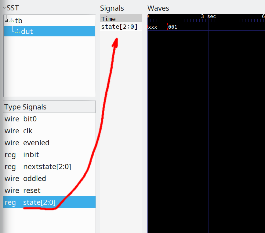
If you expand the tb tree item, you'll see dut. Select dut and you'll see the signals. Drag state into the waveform Signals pane:
![]()
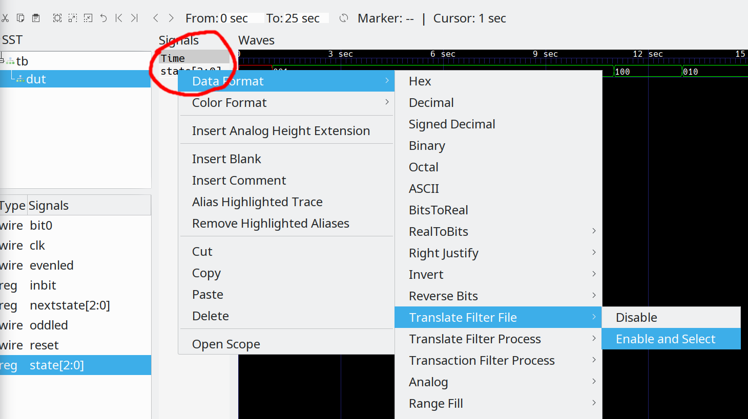
Of course, in real life you'd probably add more items such as the clock and outputs. The state variable now reads 001, 100, 010, 100. In the Signals pane, right click the state entry and then select Data Format | Translate Filter File | Enable and Select as you can below:
![]()
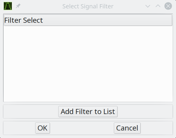
A filter select dialog will appear:
![]()
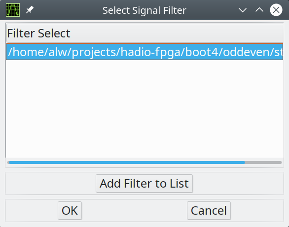
Click the Add Filter to List button and then select the state.txt file you prepared previously. That will add the file to the (now empty) list. Select the file and press OK:
![]()
Now the waveform will show the state IDs instead of numbers. Nothing has really changed, of course. It is just cosmetic. Also, the program isn't smart. Whatever is in state.txt is what is going to display even if it doesn't actually match your Verilog.
![]()
It can be a pain to set this up every time. Once you have a setup you like for a particular project, use the File | Wire Save File menu to save the setup. Then you can restore it easily.
If you use gtkwave, you ought to spend a minute with the manual. It can do a lot of things that aren't immediately obvious.
-
7▇▇▇▇ Pulling it All Together ▇▇▇▇
Let's consider what we've learned and use it to tackle a new problem.
- You have several choices of how to represent states.
- You'll use a sequential block (always with a clock) to manage the state.
- Combinatorial logic will compute the next state.
- Combinatorial logic will compute the outputs.
- A Moore machine is usually a good choice and the outputs, then, depend completely on the machine's state.
Problem Definition:
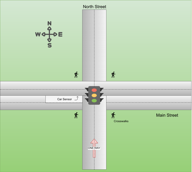
In bootcamp #0 we looked at a logic gate implementation of a traffic light. Expressed as a state machine, it would be very simple. The only input was time and the states would be Rg, Yr, Ry, and Gr where the upper case letter is the color of the north/south light pair and the lower case letter is the color of the east/west light pair.
![]()
Let's do a state machine with a little more complexity. Consider the street diagram above. Here's the key points:
- A green light on the east/west or south side of the light stays on for 30 seconds.
- After 30 seconds, the green light turns yellow for 5 seconds.
- If a car is waiting to turn when the east/west green cycle is due, keep the east-facing light red, show the west-facing green light and the turn arrow green for 10 seconds. Then make the turn arrow yellow for 5 seconds. Then start a normal 30 second green cycle for the east/west pair
- If a green cycle is about to start and a pedestrian has pushed one of the walk buttons, turn all lights red for 30 seconds before resuming the normal green cycle. There is no need to check for a second pedestrian signal. If someone pushes the button during the cycle, they will have to wait for the next green cycle
Note that North Street is one way, so there is no north-facing light. Also, although there are four crosswalks, the buttons all generate the same signal and the walk signal is shared, as well. I'll assume a 12 MHz clock, so you'll need to get the one second timer done somehow based on that clock. You may want to use more than one state machine to solve the problem.
And here are the steps you might use to solve it:
- Select states
- Select a state encoding
- Map out the movement between states
- Derive each output based on the current state
- Decide if you are using 1-, 2-, or 3-process coding style
- Write your Verilog and test
You can use my test bench <TBD> or create your own. If you do want to use my tests, here's the module definition you should match:
module trafficlight(input clk, input reset, input crossing,
    input turning, output red_s, output red_e, output
    red_w, output yellow_s, output yellow_e, output yellow_w,
    output yellow_turn, output green_s, output green_e,
    output green_w, output green_turn, output walk);
Here's the definitions:
- clk - 12 MHz clock
- reset - High to reset the module
- crossing - High when someone wants to cross
- turning - High when a car is in the turn lane
- red_s - South-facing red light
- red_e - East-facing red light
- red_w - West-facing red light
- yellow_s - South-facing yellow light
- yellow_e - East-facing yellow light
- yellow_w - West-facing yellow light
- yellow_turn - Yellow turn arrow
- green_s - South-facing green light
- green_e - East-facing green light
- green_w - West-facing green light
- green_turn - Green turn arrow
- walk - High to turn on walk signal
You may need more outputs to control internal things in your design. That's up to you.
All the inputs and outputs are positive. That is red_s is 1 if the south-facing red light is lit. The crossing input is 1 if a pedestrian wants to cross.
Before you jump over to the Verilog simulator, try to sketch this state machine as a diagram. There are, of course, many possible solutions to this problem. Obviously, a key input to the state diagram is the passage of time, even though that isn't a formal input in the module.
-
8▇▇▇▇ State Diagram Solution ▇▇▇▇
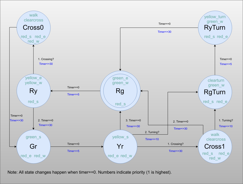
![]()
Your diagram may look different. The state names are in black and follow the format I mentioned before (Rg is red facing south and green going east and west). The purplish words in the circle are output names. The outputs assert only in the states they appear in. The lines have two marks, a black one telling you why that state change occurs and a blue one telling you what the next countdown timer value is.
The way the problem is specified, it would be possible to treat the timer reload value as another output since each state has its own individual time. However, that would be a big change if later the requirements changed so that, for example, a green light after a turn signal was only 20 seconds.
Although the requirements didn't mention it, I made crossing have priority over turning. However, crossing does check for turning if the next state is Rg. Note that keeping track of the next state after a crossing requires two cross states. Of course, you could cheat and store a bit to tell you which state was next, but that is really just keeping more state bits so it probably isn't as efficient.
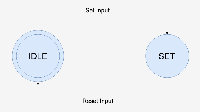
There are two outputs that are internal: clearturn and clearcross. The problem is that the turning and crosswalk indicators may not stay on the entire time we need them to. Of course, these would be asynchronous to the clock, so you'd want to put them through a synchronizing flip flop anyway (although I'll assume that's already done by the time it gets to this module). However, I wanted to use a simple state machine for both signals that is really nothing more than an RS flip flop:
![]()
There will be two copies of this, one for the car sensor and one for the crosswalk buttons. The new internal signals are to reset the flip flop once we've serviced the input.
Compare your state diagram to the ones above. If yours works, use it. If not, you can use the one provided. Now jump over to EDA Playground or your Verilog simulator of choice and implement the state machine. If you like, you can use this testbench -- which isn't comprehensive -- to see how you are doing.
-
9▇▇▇▇ Code Solution ▇▇▇▇
There are many possible solutions, of course, but here's mine. Let's break it down into manageable pieces. First, let's look at the housekeeping items. I mentioned a 12 MHz clock, although that's ugly for simulation. Because of that, I wrote two separate modules named pps to produce the one second pulse we'll need for timing.
`ifndef SYNTHESIS
`timescale 1s/1ms
// For simulation we will just do a 1PPS every other clock
module pps(input clk, input reset, output pps1);
  reg  [3:0] div;
   assign pps1=div==0;
  always @(posedge clk)
     if (reset)
       begin
      div<= 9;
       end
     else
       begin
         if (div==0) div<=9; else div<=div-1;
       end
endmodule

`else

// 12 Mhz clock divider
module pps(input clk, input reset, ouput pps1);
   reg [23:0] div=12_000_000;
   assign pps1=div==0;
  always @(posedge clk)
     if (reset)
       begin
      div<=12_000_000-1;
       end
   else
     begin
       div<=div-1;
       if (div==0) div<=12_000_000-1;
     end
endmodule
`endif
If the symbol SYNTHESIS is defined, you'll get a real one second pulse. But if it isn't, we assume we are simulating and just divide the input clock by two. The divider itself is unremarkable.
The other item is the RS filp flop used for latching the vehicle sensor and the pedestrian button. Not much to worry about here, either.
// Here Q is a 1 bit state; 0=idle, 1=set state
module rssm(input clk, input reset, input set, input clear,output reg q);
   always @(posedge clk)
     if (reset) q<=1'b0;
     else
       begin
      if (set) q<=1;   // the way this is written set will have priority over clear
      else if (clear) q<=0;
       end
endmodule
Both of these utility modules show up in the main code:
   pps onesecdiv(clk,reset,onesec);
   rssm crossff(clk,reset,crossing,clearcross,iscross);
   rssm turnff(clk,re
Notice the reset to the pss module? This could be a problem if some states shifted before the count ran down. You could get a short second to start with. In this case, it isn't a problem, and the precision isn't that important, anyway.
Defining States
The states are local parameters and use one hot encoding. In addition, I made parameters for the different delays in case I want to adjust them. There's variables for the current state, next state, the timer, and a next timer value, including the reset I mentioned earlier.
  // States
   localparam Rg=1;
   localparam Ry=2;
   localparam Gr=4;
   localparam Yr=8;
   localparam RgTurn=16;
   localparam RyTurn=32;  // Yellow arrow/Green light + Red light
   localparam Cross0=64;
   localparam Cross1=128;

  // Delays in 1s units
   localparam lightdelay=30;
   localparam yellowdelay=5;
   localparam turndelay=10;

  reg [7:0] state;
  reg [7:0] nextstate;
  reg [6:0] timer;
  reg [6:0] nexttimer;
If you wanted delay of more than 63 seconds, you'd need to widen the timer and nexttimer variables.
Output
Once you know the states, writing the output functions is quite simple, especially since it is easy to interpret the one hot states. You just need a series of assign statements.
// outputs
  assign red_s=((state&(Rg|Ry|Cross0|Cross1|RgTurn|RyTurn))!=0);
  assign red_e=((state&(Gr|Yr|Cross0|Cross1|RgTurn|RyTurn))!=0);
  assign red_w=((state&(Gr|Yr|Cross0|Cross1))!=0);
  assign yellow_s=state==Yr;
  assign yellow_e=state==Ry;
  assign yellow_w=yellow_e;
  assign yellow_turn=state==RyTurn;
  assign green_s=state==Gr;
  assign green_e=state==Rg;
  assign green_w=((state&(Rg|RgTurn|RyTurn))!=0);
  assign green_turn=state==RgTurn;
  assign walk=((state&(Cross0|Cross1))!=0);
  assign clearcross=(state==Cross0)|(state==Cross1);
  assign clearturn=state==RgTurn;
Don't forget the clearcross and clearturn outputs are internal and used to reset the two rssm modules that latch the sensor inputs.
Next State
The code that sets the next state starts by setting the nextstate to be the current state and the nexttimer value to 0 which indicates there's no reason to load the timer. It is crucial that these are always set to something and this makes sure of that. If you later write something over either variables, that will take precedence.
After that's out of the way, a case statement provides logic for each possible state. Here's a few examples:
  // next states
  always @(*)
    begin
      nextstate=state;  // default is stay where you are
      nexttimer=0;  // by default let PPS run and don't do anything
      case (state)
        Rg:  // East/West Green
          begin
          if (timer==0)
            begin
              nextstate=Ry;
              nexttimer=yellowdelay;
            end
          end
        Ry:   // East/West Yellow
          begin
              if (timer==0)
                if (iscross)
                  begin
                nextstate=Cross0;
                    nexttimer=lightdelay;
                    end
                else
                  begin
                  nextstate=Gr;
                  nexttimer=lightdelay;
                  end
The Rg state is simple. When the timer expires, it goes to the Ry state. But Ry is a bit more complicated. It checks the timer, but when it expires, the next state will depend if there is a pedestrian waiting or not. The rest of the states have similar logic.
The case statement, by the way, has a default case. This would imply we forgot a state or -- worse -- the state machine somehow got an illegal state. To be safe, we go to pedestrian mode which should result in a 30 second all red condition and then return to some sane operation.
        default: // huh?
            begin
              nextstate=Cross0; // Go all red for 30 seconds and recover!
              nexttimer=lightdelay;
            end
The Core State Machine
Once you have all this done, the actual state machine is almost too simple. Its only job is to set the state and timer variables.
// Actual machine
  always @(posedge clk)
    if (reset)
      begin
        state<=Rg;
        timer<=lightdelay;
      end
    else begin
      if (nexttimer!=0)
        begin
          timer<=nexttimer;
        end
     else
       begin
         if ((onesec==1)&&(timer!=0)) timer<=timer-1;
       end
      state<=nextstate;
    end
There's not much to talk about here. A reset starts the system up with state=Rg and timer=lightdelay (30 seconds). If nexttimer isn't zero, we set timer and reset the pps module. In normal operation, the state machine tests for a one second pulse and decreases the timer (assuming it is not already zero). In all cases, the code sets state to nextstate.
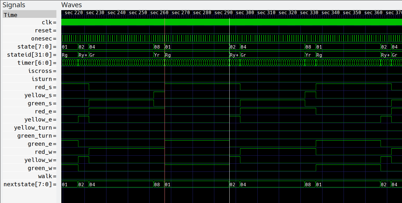
How did you do? You can simulate my code in EDA Playground or your choice of Verilog simulators. The testbench could be improved to test corner cases like both sensors asserting at once, for example. Here's some output from my testbench (using gtkwave):
![]()
-
10▇▇▇▇ Extra: State Machine Design Tools ▇▇▇▇
There are several options for using software to develop state machines using some sort of GUI or tabular input. One tool is Fizzim, which is open source and easy to use. It makes good looking diagrams, so even if you don’t want to generate code, you may still want to check it out. Fizzim uses Java for the GUI, so it will run almost anywhere. It uses Perl as a back end code generator and, again, that’s pretty portable.
You don’t actually have to use the GUI, if you want to stick with manipulating text, but the GUI is handy. There are three object types: the state machine, states, and transitions. Each element can have attributes that describe different things for the back end Perl program.
The Fizzim tutorial is well worth reading even if you may not want to use Fizzim. In the course of showing the tool, they also cover practical nuances of state encoding, output generation, and coding state machines in Verilog. The latest version can also output VHDL.
FPGA Boot Camp #4: State Machines
Most FPGA projects will have at least one state machine. Learn how to create these powerful little dedicated CPUs in your designs.
 Al Williams


Discussions
Become a Hackaday.io Member
Create an account to leave a comment. Already have an account? Log In.