-
Pedal_Control Test Video
05/29/2019 at 02:50 • 0 commentsHere's a video of our Pedal_Control program running.
https://www.youtube.com/watch?v=4zGgB08z7JI&feature=youtu.be
-
May Update
05/28/2019 at 15:58 • 0 commentsWe have made substantial progress, transforming our raw materials into a working, moving frame. Images of our progress is available in the gallery.
Steering Wheel:
We 3D printed a steering wheel to be used with our car. Mounted to the steering wheel is an IMU, which detects how many times either clockwise or counterclockwise the wheel has been rotated. By utilizing a counter with our code, the steering wheel can be rotated either clockwise or counterclockwise up to 900 degrees, which can be used to modify the motor power while turning. The code for our steering wheel can be accessed in the files section, under Steering_Wheel.ino.
Drive Train:
Our vehicle is powered by a total of four CIM motors. Our vehicle uses two 3-stage EVO CIM gearboxes (14.17:1 ratio) , each of which takes two motor inputs. The gearboxes and motors are mounted on either side of the frame.
Each motor is hooked up to a Jaguar motor controller. This lets us code the DC motors as if they were normal servos, using Arduino.
Each motor controller is plugged into a power distribution panel, which in turn is plugged into a 12V battery.
The weight of the frame as well as friction from the new wheels makes building a physical steering rig, as was used in our stock Power Wheels car, difficult. Thus, we aim to use skid steering to guide the car, with the steering wheel's inputs being used to automatically adjust the speeds of the left and right motors.
Our vehicle utilizes front wheel drive. For the rear drag wheels, we initially used a set of omni wheels mounted to 1/2" churro axle. Upon testing, the wood holding the churro axle split and we had to replace the rear wheels.
We opted to use a set of castor wheels for their low-friction, and stability in being screwed directly into the plywood frame of the car.
Testing:
Even after construction of our drive train was complete, testing was a long process of trial and error simply to get the vehicle to move. One of our biggest issues was that the gearbox output was a hexagonal axle, and our wheels had circular hubs. We 3D printed multiple different adapters, but each was worn down by the weight and torque of the vehicle. Ultimately, metal hexaxle hubs got the job done, as can be seen with the side view photo in the gallery.
In testing with the Drive_Forward program, we found that the left motors moved faster at quarter speed than the right motors, so we had to account for this in future programming.In the Acceleration_Pedal program, we aimed for an acceleration pedal to move the vehicle forward, and for the brake pedal to stop the movement. Unfortunately, we were unable to get this program to work.
In the Pedal_Control program, we opted for an alternative steering method. Rather than relying on an acceleration and brake pedal in conjunction with a steering wheel, we have a left and right pedal (as pictured in the gallery). When the left pedal is pressed, the left motors spin, and vice versa. This program was successful.
-
April Update
04/12/2019 at 01:59 • 0 commentsWe've made quite a bit of progress on the car since January. First and foremost, all materials to construct our chassis, including 80/20 aluminum bars, three-way connectors, and screws have arrived, and we are in the process of completing the chassis. We have made some progress in other fronts as well:
Motors:Although our initial plans called for using two drive motors, in calculating the torque necessary to move an average adult of 180 pounds, we have determined that our car will need to be equipped with four 12V DC motors. As such, our car will use skid steering to navigate, which we will need to code.
Battery:We will be using a simple 12V battery available to us in the lab. This solves one of our obstacles of acquiring a 64V battery.
Ultrasonic Sensors:
We are using four Maxbotix Ultrasonic Rangefinder - LVEZ4 sensors
Seat:
We are using a ZXTDR Seat for Drift Trike Racing
Wheels:
We are using Marathon 00210 Universal Fit wheels
Steering Wheel:
We 3D printed a steering wheel for our car. An image of the printed wheel is posted in our gallery.
-
January Update
01/23/2019 at 14:47 • 0 commentsDue to some delays, we have had to push back our build schedule. Our revised schedule can be found here.
https://docs.google.com/document/d/16GOUXHAd7xvJrtRl-44KlLluDAhO5_ExsurhShvZ_mo/edit?usp=sharing
Once our materials arrive, we are set to begin constructing our aluminum chassis. In the mean time, we are looking into what motors and batteries to use, as well as how to construct a steering mechanism for the car.
-
Web Update
12/07/2018 at 20:31 • 0 commentsAt this point, we have spent a significant amount of time searching for and choosing the specific parts we will need for the remainder of the project. Currently, our main focus is constructing a new aluminum chassis to replace the one that is currently part of the Power Wheels vehicle. This will increase greatly increase the durability of our vehicle so that is able to support the weight of an average adult. Recently, we removed the original wheels from the vehicle and are preparing to detach the plastic shell from the rest of the vehicle. The raw materials for chassis construction have been ordered as well. Chassis construction is the next task at hand and we will begin that as soon as our materials have arrived. Once the chassis is completed we will attach the plastic shell to it to maintain the original look of the vehicle.
-
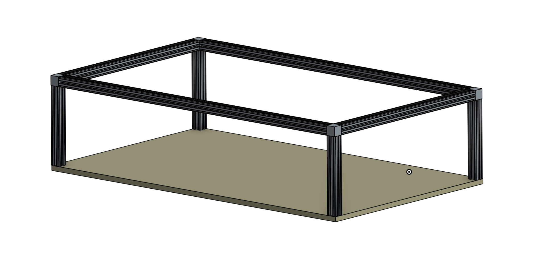
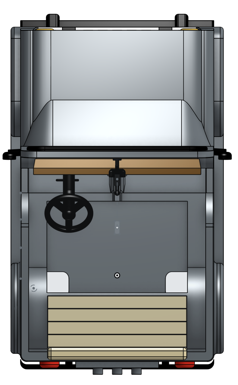
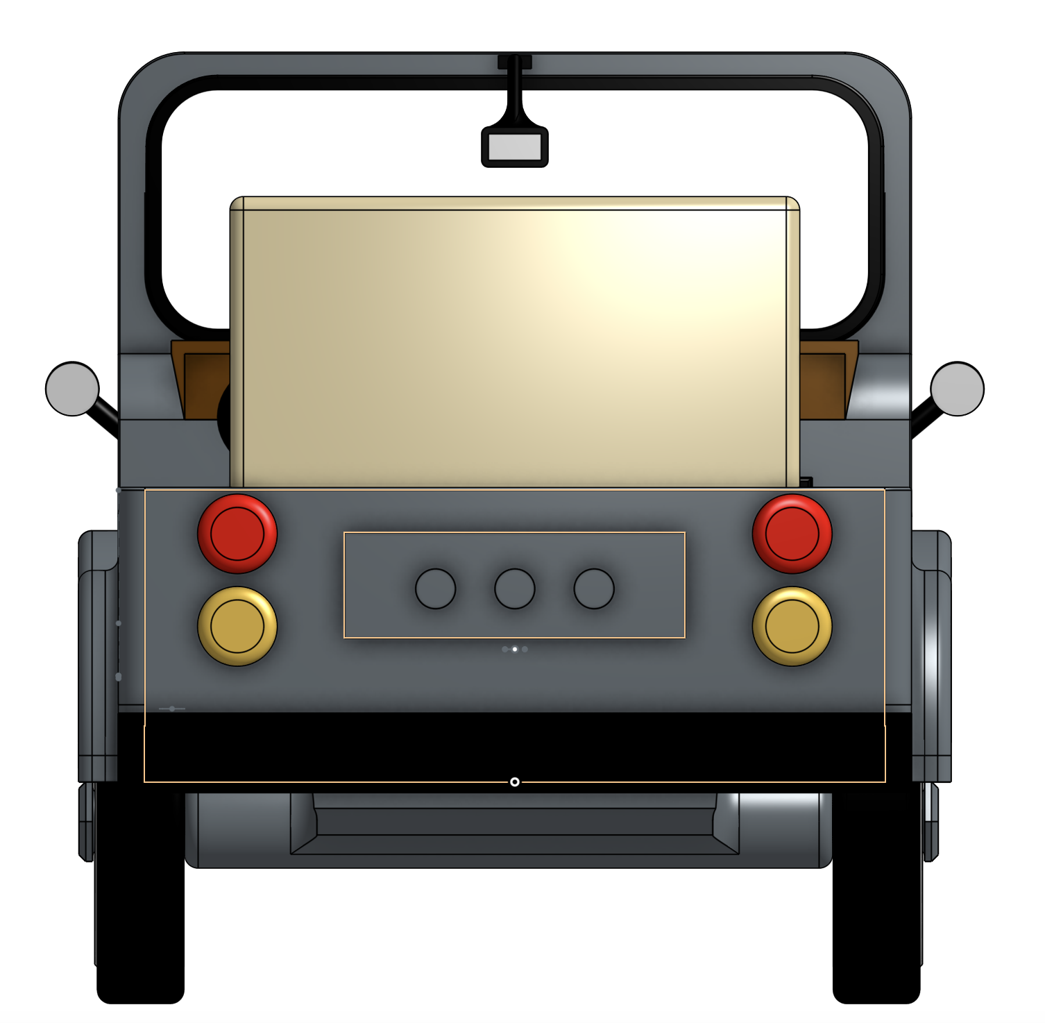
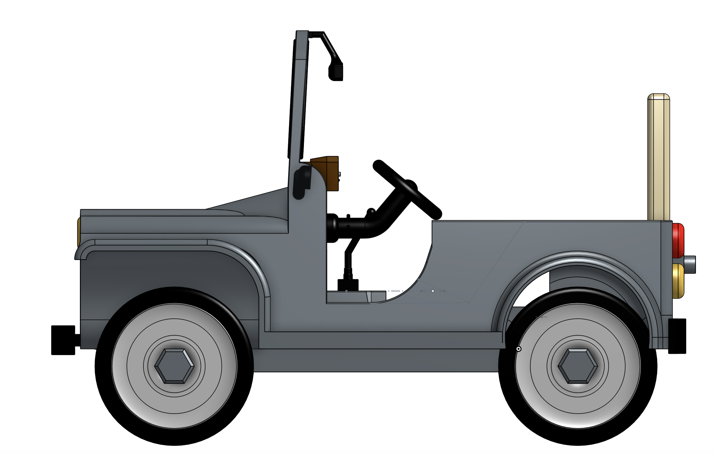
CAD Designs for Final Look & Underneath Frame Box
11/06/2018 at 16:26 • 0 comments![]()
![]()
![]()
![]()
-
Research Proposal
11/06/2018 at 16:19 • 0 commentsWe finished our final proposal, which outlines our problem, objectives, and approach for this project. Our proposal can be read here:
https://docs.google.com/document/d/1WcoMT9AB_8yNUt0sjX5nhp3J5i4iLcpf7cEoZHsvjbk/edit?usp=sharing
Self-Driving Power Wheels Car
Retrofitting (and overhauling) a Power Wheels car to make it self-driving.