 Timo Birnschein
-
1Get Things Installed
What is needed:
- Inkscape 0.92 I strongly recommend downloading and installing manually to avoid confusion with the folder structure later
- Chain Paths Extension This is a must have for working with DXF files. I'll go into detail on how I use this down below
- Laser Cutting Template with multiple layers designed for easy import into VisiCut
- Java JDK 8u192
- Netbeans SE
- VisiCut with some of my own modifications
- VisiCut config file
- CodeBlocks with MingW to compile SimpleG from sources
- Git for Windows (if you use Windows) to clone the SimpleG software
- SimpleG for transferring gcode to the laser fast (without interruption of the stream up to a certain speed)
Install and download everything in the above order.
Open a console (hit Win, enter "cmd", hit enter). Where ever you are at this moment, I recommend creating a batch file and add this command:
"G:\Seafile\Software\CNC Software\Laser Cutter\SimpleG\bin\release\SimpleG.exe" -p COM5 -f "e:\Users\timob\Documents\output.nc" -F "G:\Seafile\Software\CNC Software\Laser Cutter\SimpleG\bin\release\SimpleG-end.gcode"You obviously need to adjust all paths to your filesystem and the comport to the comport your GRBL communicates through, but you get the idea. With this in place, I just open a command console, enter SimpleG.bat and the process starts. I always use the same output.nc file for the files VisiCut exports which makes this very easy to use and a 5 second process to get something to cut.
-
2Design The Part
I use Solidworks for this step, most of the time. For 2D objects, laser cutting is brilliant, fast and has a very high quality.
If I need 3D parts, I use the sheet metal tools Solidworks provides. You can easily make bent sheet metal parts on a laser but you need to design the living hinges yourself. That requires a bit of trial and error as it the material properties need to be taken into account. Thick plywood 6mm requires larger hinges than 3mm plywood. I never tested to make living hinges with acrylic but I guess that works as well when the material is not bent cold.
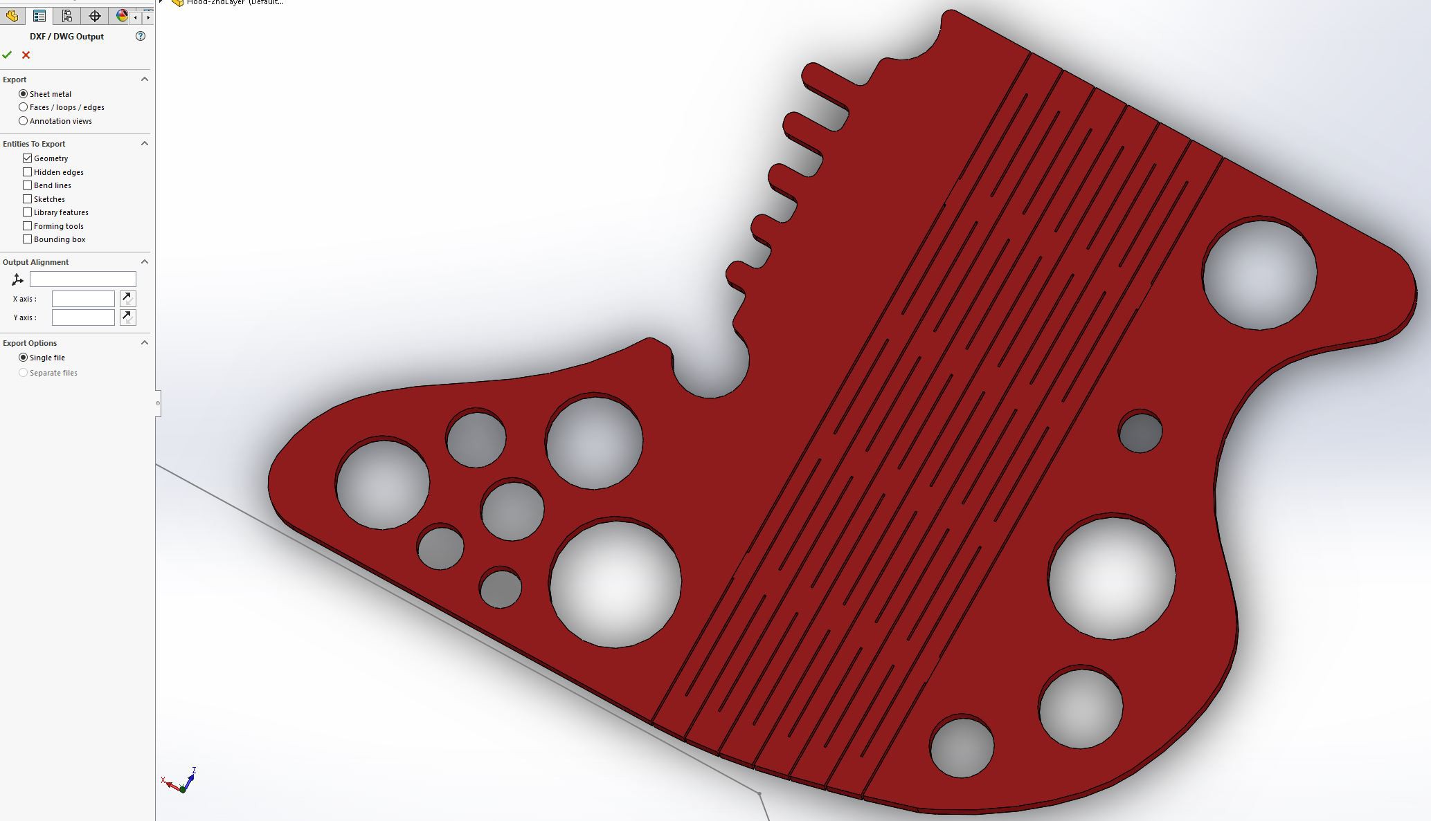
Right click on the surface you want to export as a dxf file, look for Export to DXF / DWG, choose a filename and hit OK in the following menus.
There is a caveat, though. If you have bent sheet metal and you flatten it before exporting it, it is important to choose "sheet metal" in the following export options.
![]()
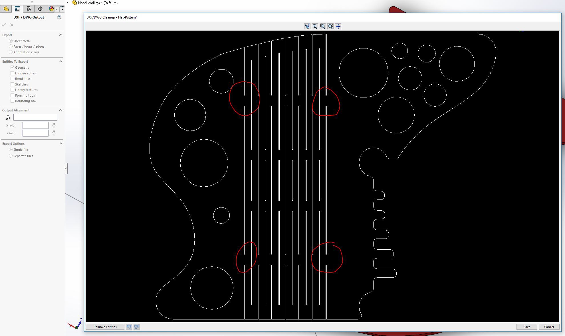
In the menu on the left, sheet metal is selected. In the image on the right, if looked at closely, you can see the bend lines on the left and right edge of the living hinges. If faces / loops / edges is selected instead, those bend lines will show up in the exported DXF, ruining the part when laser cut! Look at the following example:
![]()
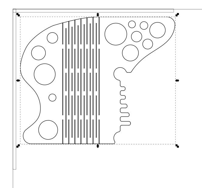
The lines are solid and will be cut! Creating not nice living hinges and one solid part but instead three separate parts. If correctly selected sheet metal during export, these lines disappear and the cut is possible:
![]()
Tadaa!
This can now be processed by Inkscape in the next step.
-
3Import Into Inkscape And Chaining Paths
The dxf file that is produced by Solidworks contains individual paths. A rectangle in the exported file is represented by four individual lines that the laser happily cuts - just not in the right order which is incredibly inefficient. Unfortunately, VisiCut is not good at understanding that, so we need a way to chain all these paths before we start cutting.
In additional to chaining all paths, we need to bring the work into a certain order to make sense.
- Picture (raster) engravings should be done first.
- Then, vector engravings.
- After that, holes should be cut.
- Lastly, the perimeter needs to be cut.
Working in this order ensures that nothing moves out of alignment before the the part is separated from the material.
My Inkscape template adds another step 0 which ensures the laser is primed. For some reason, my laser needs kind of a heat up phase and will not cut right away otherwise. So I vector engrave the coordinate origin to do that.
![]()
In my template, I left out the raster engraving but it can be added easily later. I just rarely use raster engraving anyways because it's so bloody slow and prone to ruin your part if not set up and calibrated correctly.
We need to import the previously saved DXF file now. Just import the file by clicking File -> Import. Then select your file, hit OK in the following menu and move the imported structure the the top left. Leave a little bit of space.
![]()
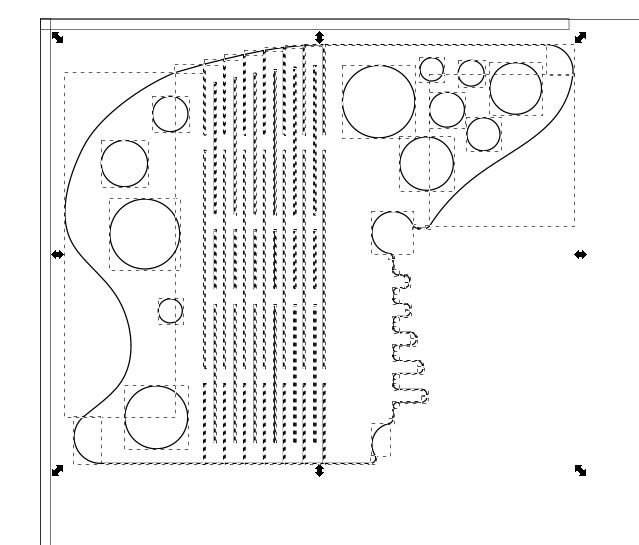
You will notice, this is one big object. We need to hit CTRL+Shift+G a couple of times to ungroup the object:
![]()
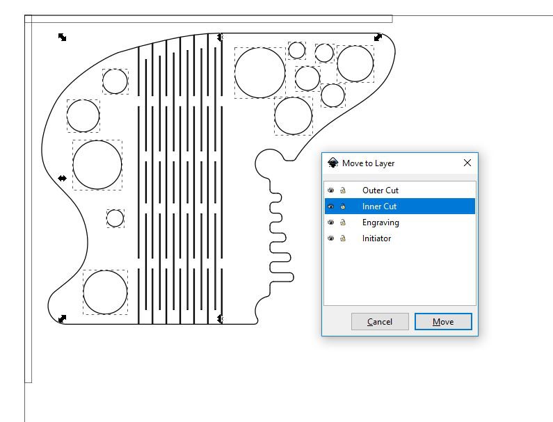
Now select all circles and move them all to the layer Inner Cut.
![]()
They need to be moved out of the way for now. I did the same for all rectangles that are part of the living hinges which are NOT part of the outline cut as well. Please note the picture below DOES show the rectangles still on the Outer Cut layer. That's my mistake. Please ignore.
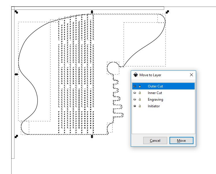
Next, move the outer cut to the Outer Cut layer.
![]()
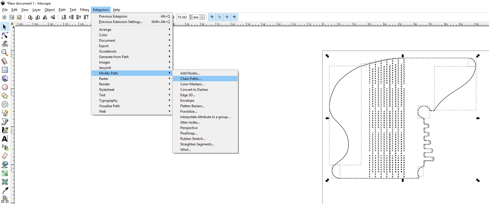
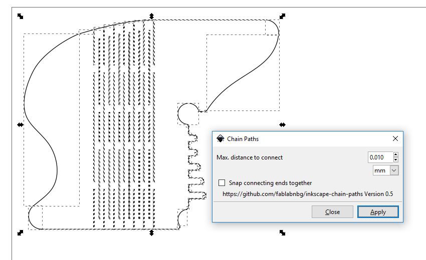
Next, we need to chain the paths.
![]()
Select every path that needs to be chained. PLEASE DO NOT CHAIN CIRCLES! They already come chained. Chaining them, breaks them. Try it and see what happens and then hit CTRL+Z for undo immediately.
![]()
Hit Apply and then Close. Everything is done now.
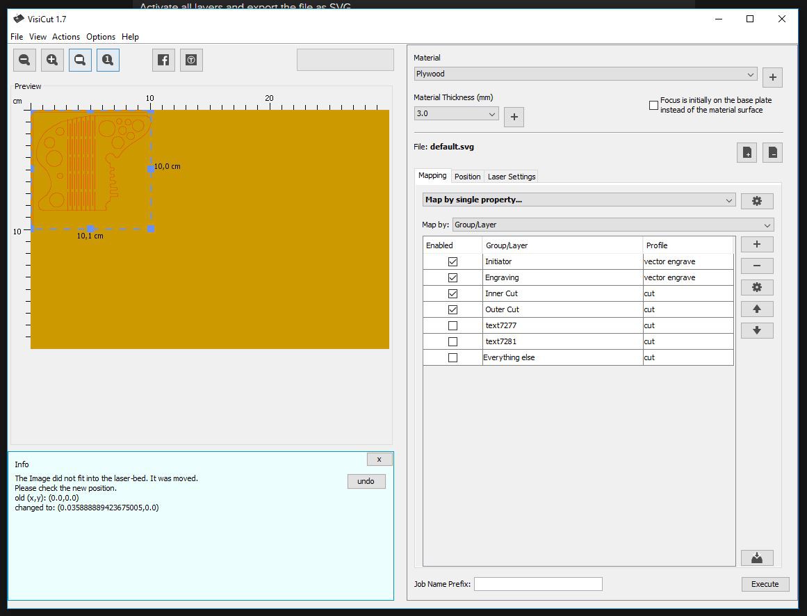
Activate all layers and export the file as SVG.
![]()
Next up: VisiCut and how to create the laser cut NC file.
-
4VisiCut
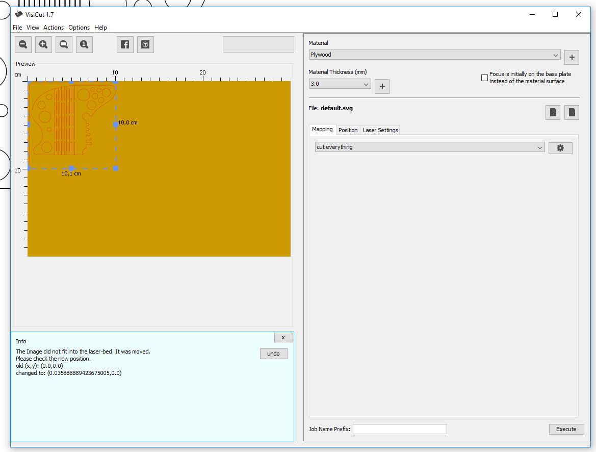
Start by importing the newly saved SVG file. It will load up as a vector representation of the vector file you just saved.
![]()
You can now click on the tab Mapping and select Map by group / layer or Map by single property.
Select the layers you want to cut and engrave and select the appropriate profile. Make sure the order is correct. If not, move stuff around by using the arrow buttons on the right.
![]()
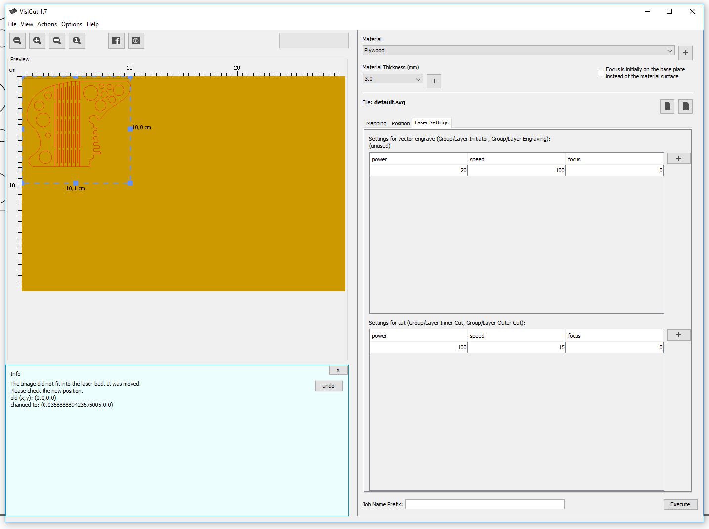
Check under Laser Settings if BOTH settings for cutting and engraving show up and make adjustments as needed for your machine.
![]()
Lastly, hit File -> Export Laser Coder and write a file called output.nc to the location of your choice. Please note, the next step uses my SimpleG.bat file to start and configure SimpleG. The file needs to be in the correct location for that unless you want to enter the entire command every time you run SimpleG.
However, SimpleG is totally optional. Output.nc can be cut with any gcode sender of your choice. I'm sure there are better options out there.
Bottom line: The entire job is now in the same file. All engravings and cuts without the need to run a second file. I love the simplicity of this!
-
5Cut the Work
I use SimpleG for executing my gCode with GRBL. It has proven to be reliable enough to even run larger jobs that take 30 minutes to an hour.
![]()
All there is do to is to open a console and run the SimpleG.bat file after configuring it correctly. This will promt you to be careful and not burn your house down by leaving the room and hoping everything goes according to plan.
USE AT YOUR OWN RISK!!!
As soon as you hit enter, the machine will query GRBL, ask for the latest configuration and then wait for you to hit enter again to start the cut.
If you got this far without errors on the console, you can be reasonably sure be sure the rest will run smoothly. At least for me, this was almost always the case.
![]()
Run a couple of smaller tests first. Then larger projects. Leave a comment down below, if you encounter any issues with anything. I'll try my best to help.
Inkscape + VisiCut = Perfect Lasercutting Workflow
A brief summary on how I use my K40 laser cutter with custom GRBL controller. However, this workflow should work for all GRBL lasers.


Discussions
Become a Hackaday.io Member
Create an account to leave a comment. Already have an account? Log In.