bornach
-
Final Assembly
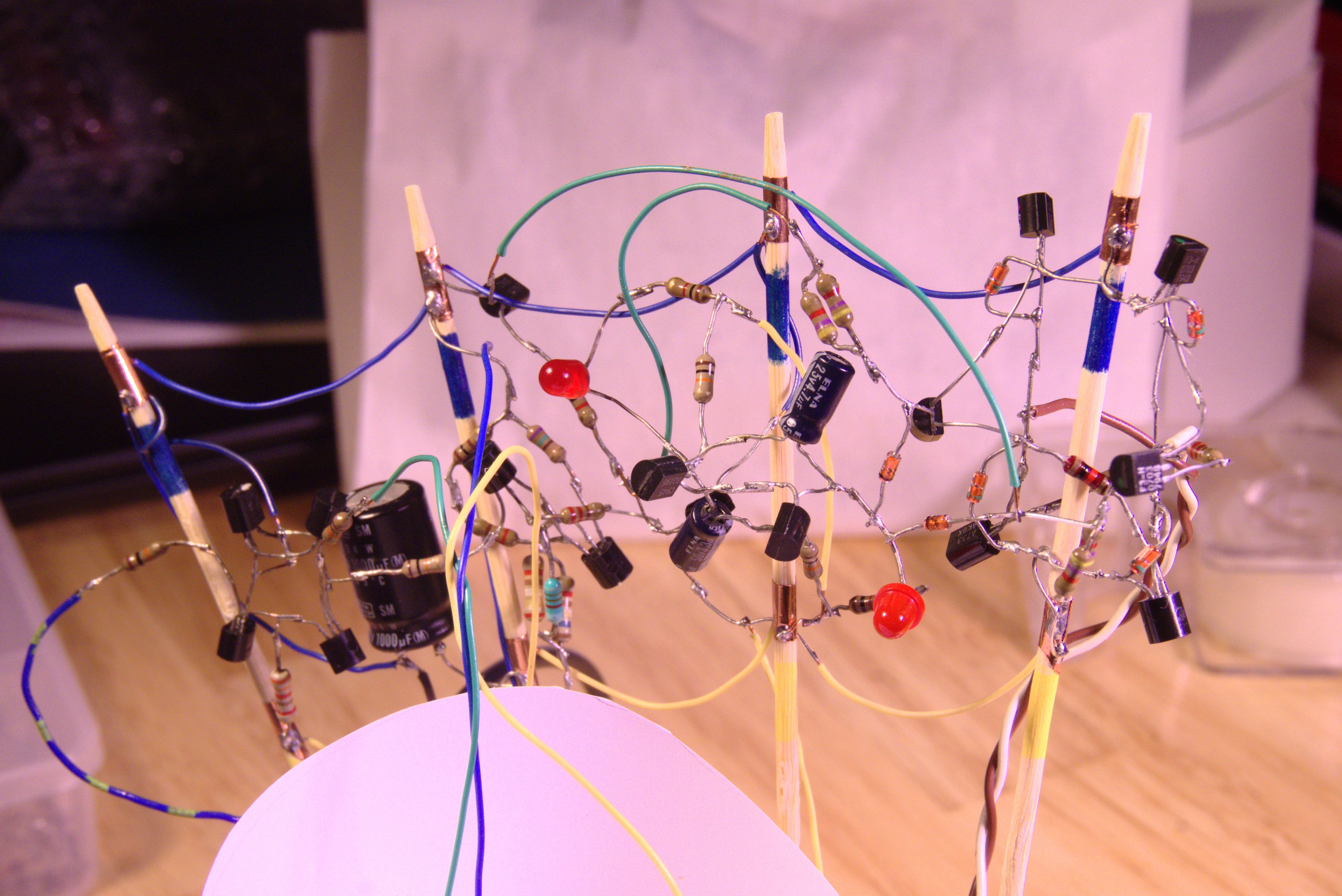
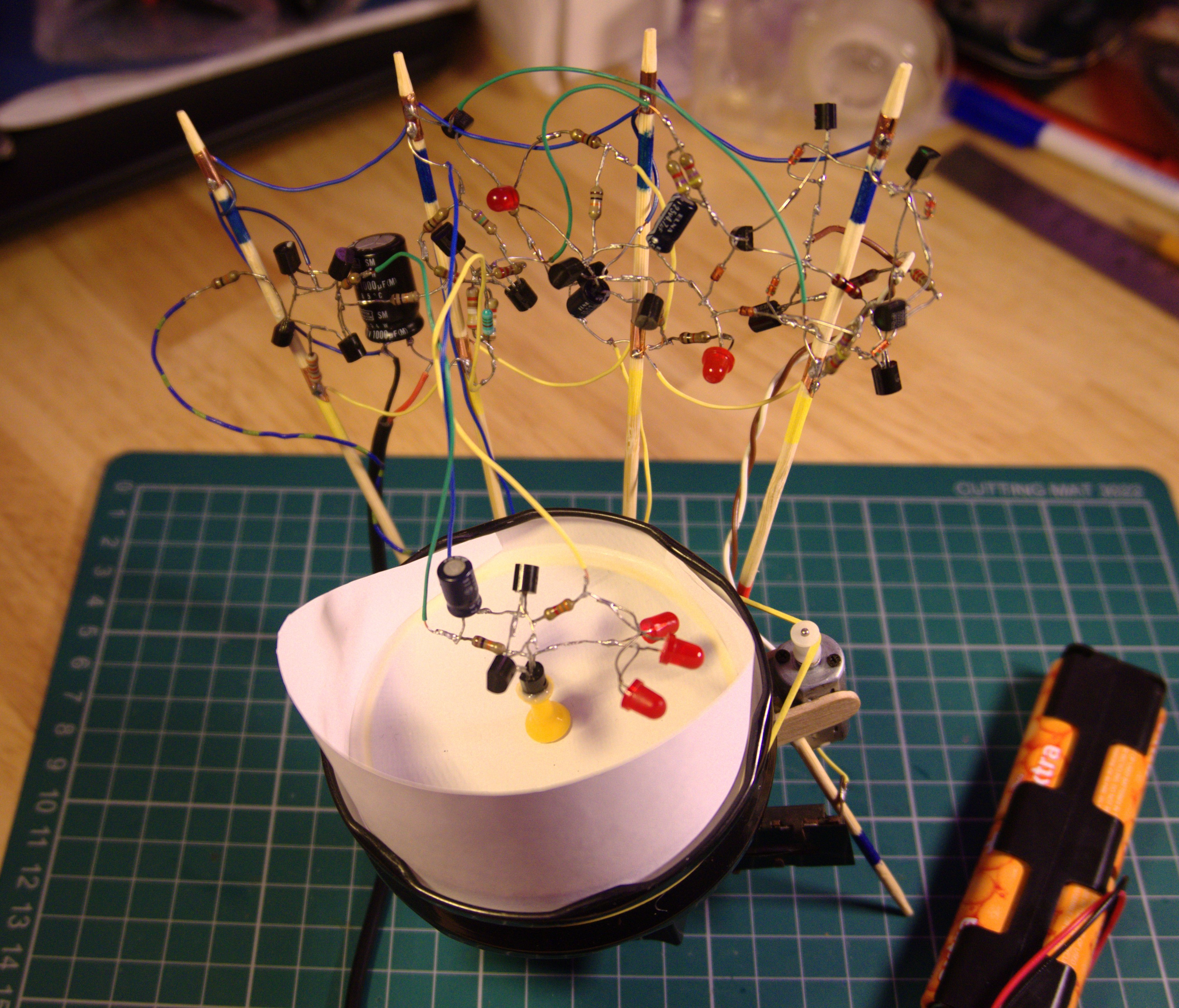
01/06/2019 at 18:15 • 0 commentsThis ugly mess of a circuit sculpture is the final result of integrating all those functional components together:
![]()
This is the antithesis to Eirik Brandal, @MohitBhoite and Boldport. This is deliberate not just for lack of spare time, but also as a nod to my Dad who's own hacks always prioritised function over beauty.
I'm using a loose wooden frame to support the circuit vertically in the air. You can just about recognise each of the functional units documented in previous log entries. I've wrapped copper tape around the wooden supports to provide anchoring points to which the circuit is soldered, and to also provide the DC power of 5 to 6V.![]()
I've added a PNP transistor and NPN transistor to connect the output of the Schmitt trigger to the control inputs of the H-bridge. Changes in light level cause the DC motor to change direction. Two diodes connect the bases of the H-bridge control transistors to the collector of one of the NPN transistors in the multivibrator. This implements a crude PWM that runs the DC motor at a slow speed. I also added an RC filter to the output of the light sensing unit to smooth out some of the erratic motion that would result from noise. Also had to add a 1000uF electrolytic capacitor across the supply voltage to help stabilise the voltage levels - running a DC motor with PWM tends to introduce big voltage swings. It's a wonder this works at all when using just a single power supply - typically we would want the motor driver on a separate supply from the control and sensing circuit. This could still be done in the future.
All the wires are solid core for extra rigidity. In keeping with the theme of recycled electronics, all the wire is either from discarded stock or from Dad's junk bin. The yellow and blue wires are discards I find near junction cabinets - BT engineers over here tend not to tidy up after fixing people's landline and broadband connections.
-
H-Bridge
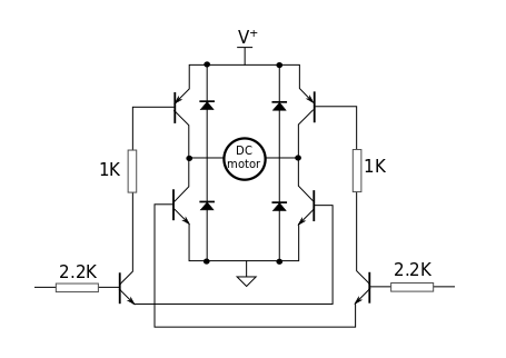
01/06/2019 at 17:53 • 0 commentsThe H-bridge is made from 4 NPN transistors, 2 PNP transistors, and a few resistors.
![]()
I tried to preserve some aspects of the "H" when soldering the components together. The flyback diodes were also from Dad's collection of recycled components, although I didn't show these in the build log.![]()
The two verticals wires join the collectors of the NPNs to the collectors of the PNPs. This is where the DC motor will be soldered in the final assembly. I couldn't find the exact resistor value as in the prototype, so I've used resistors in series and resistors in parallel where needed. I do not expect this circuit to perform optimally.
-
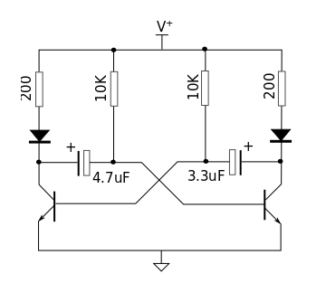
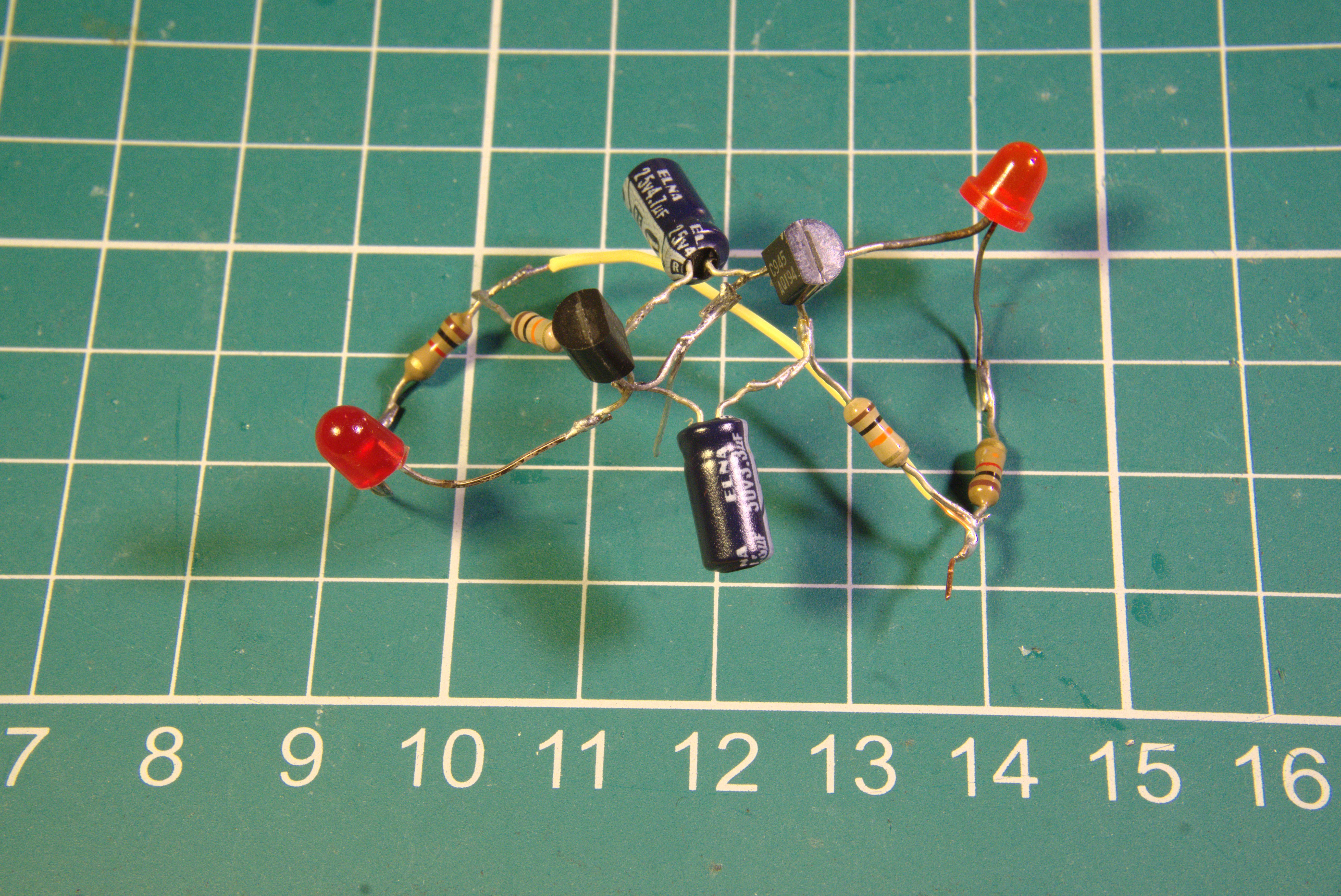
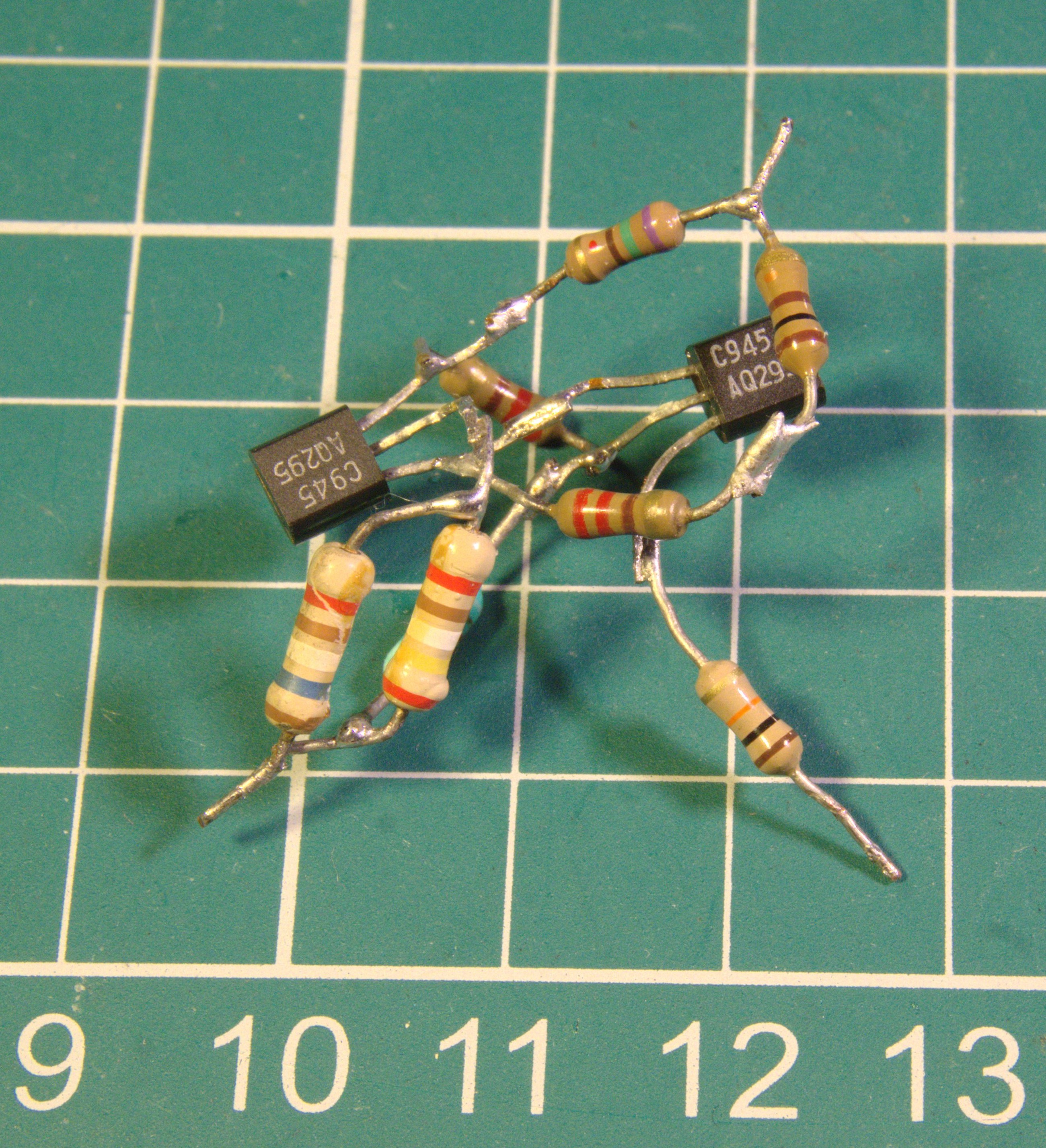
Astable Multivibrator for PWM
01/06/2019 at 17:41 • 0 commentsI like making these oscillators from discrete components. I have the circuit memorised. They can easily be modified to trigger some other circuit periodically.
![]()
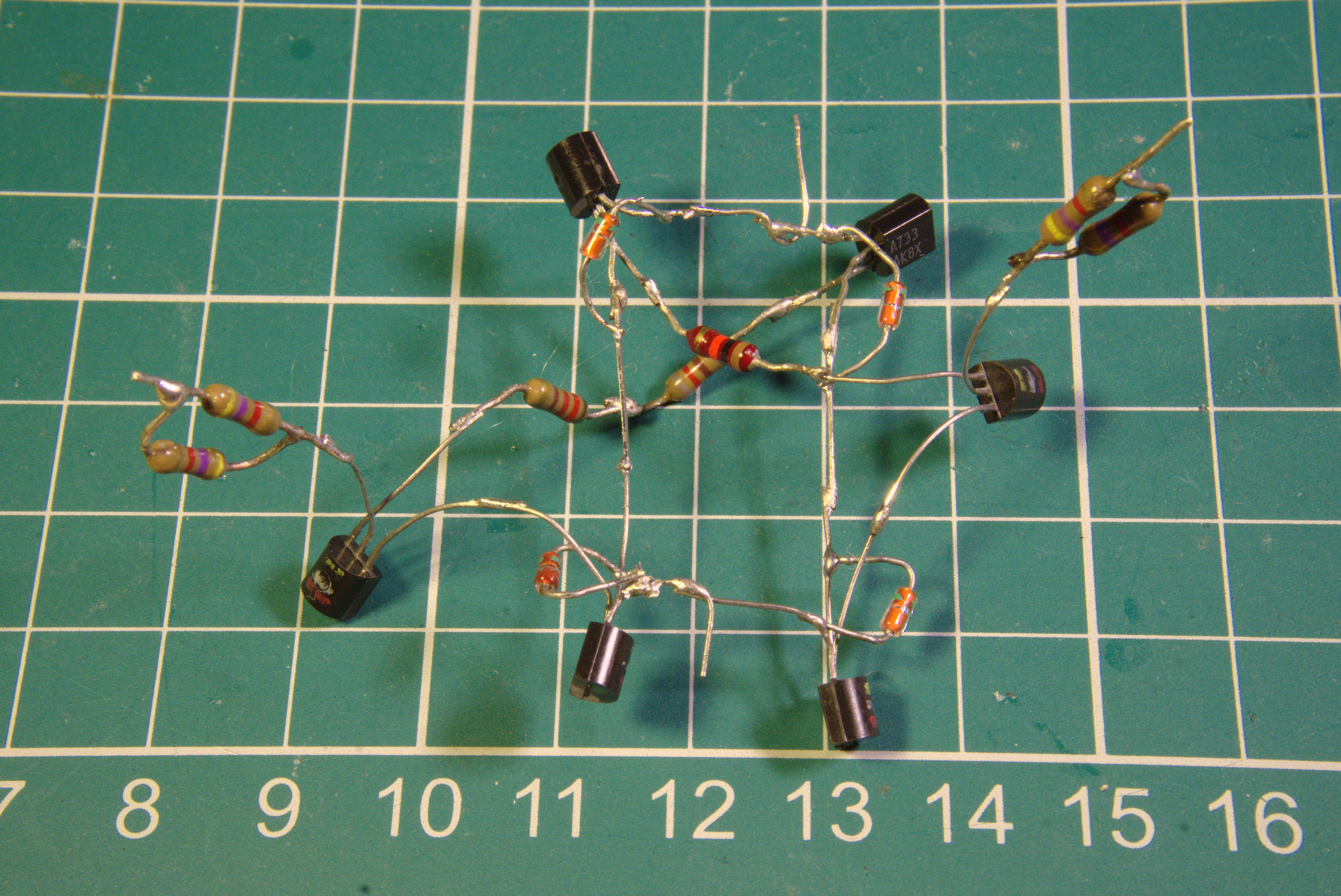
This is what it looks like soldered without using a circuit board:
![]()
I had to resort to adding an extra connecting wire. I didn't want it to end up looking like the tight cluster of the Schmitt trigger since I would need easy access to the collector of one of the transistors when implementing the Pulse Width Modulation.
As an aside - I once used a boardboard version of the multivibrator to drive the percussion inputs to a Casio MT-205.
The plan here is to do something similar with an H-bridge to reduce the speed of the DC motor. I've chosen the resistor and capacitors to oscillate at tens of cycles per second and to give a duty cycle of just about 40%
-
Schmitt Trigger from 2 NPN Transistors
01/06/2019 at 17:31 • 0 comments![]()
This logic level Schmitt trigger uses 2 NPN BJTs and resistor values I copied from another YouTube video that describes how it works:
I didn't put much effort in planning how to layout the components. The form just emerged from how everything needed to be connected without resorting to adding extra wire. The result was this tight knot of components.
-
Voltage Comparator
01/06/2019 at 17:23 • 0 commentsThe voltage comparator is simply 2 PNP transistors forming a long-tailed pair with a resistor current source. A current mirror using 2 NPN transistors makes it output the result on a single wire.
![]()
I learned how to create this comparator from discrete BJTs by watch a YouTube video by [a2aew]
-
LEDs as light sensor
01/06/2019 at 17:16 • 0 commentsTo increase the light sensitivity, I've used 3 of these old LEDs in parallel. The reversed bias current is still only microamps. To amplify this tiny current, I'm using 3 NPN transistors in a Darlington configuration.
![]()
-
Breadboard Prototyping
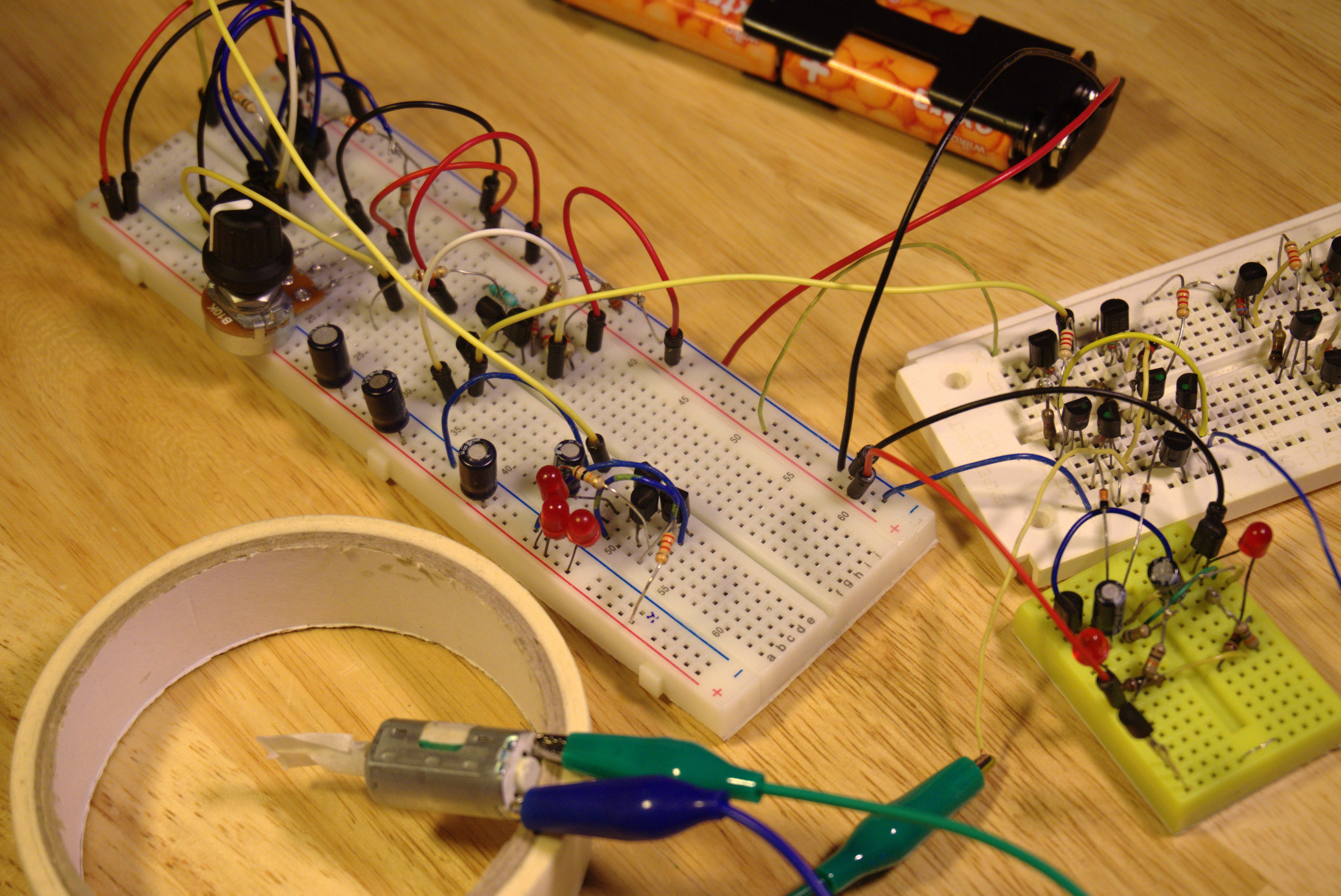
01/06/2019 at 17:07 • 0 commentsI decided to limit the electronic components that I could use to only those in Dad's recycled assortments.
Dad didn't have any microcontrollers or motor controller ICs in his collection and so I attempted to create the comparator, PWM generator and H-bridge from discrete transistors and resistors. Dad also didn't have any light dependent resistors but he did have a handful of very old LEDs. These were not very bright but they could function as a light sensor when reverse biased.![]()
One problem with Dad's recycle components is that because they were desoldered from a circuit board, the legs were very short and encrusted with solder. This made them unsuitable for use in a breadboard prototype. So I've used some new components during the prototyping with the intention to swap them for the recycled equivalents when soldering the final circuit. -
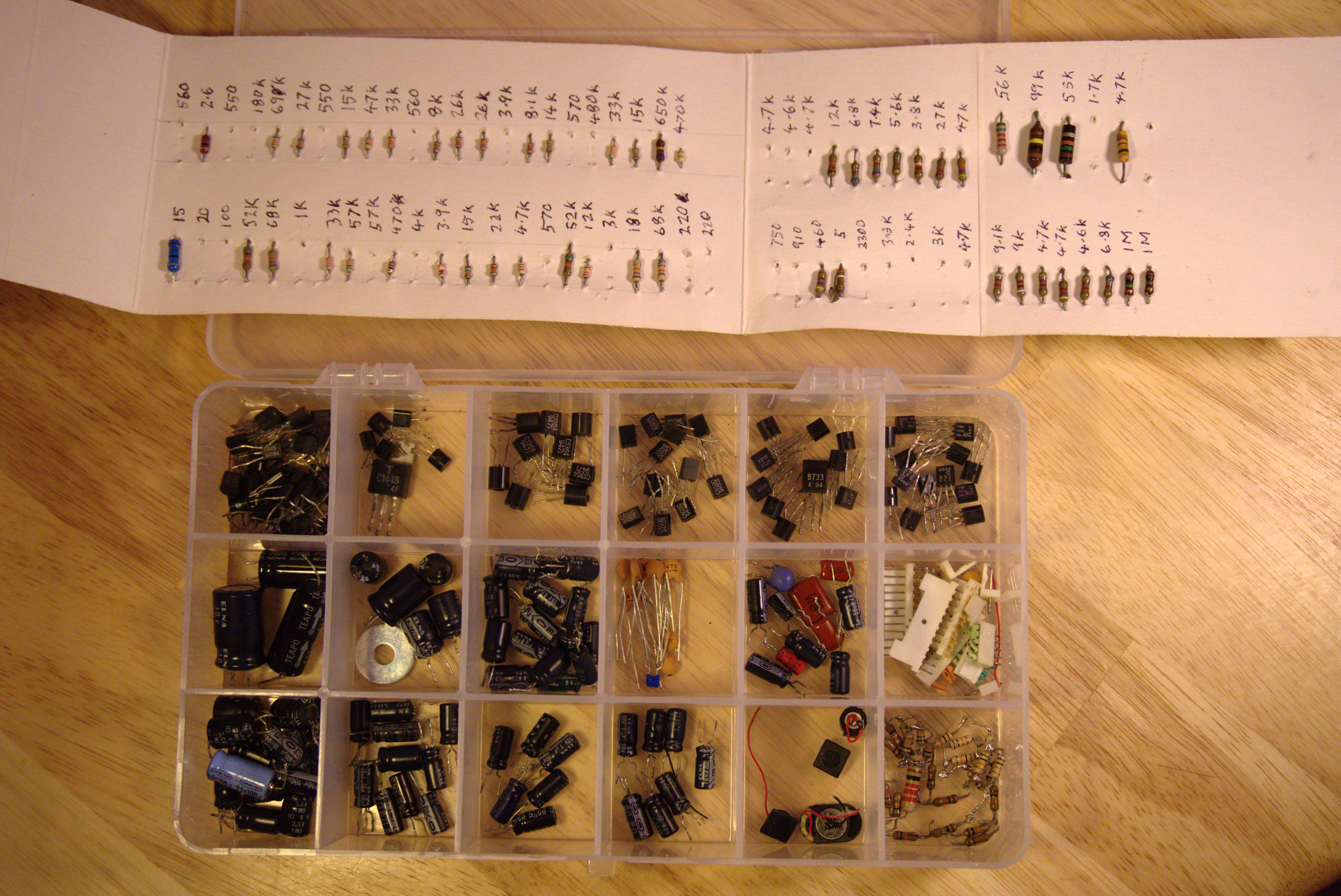
Dad's Homemade Assortment of Electronic Components
01/06/2019 at 16:53 • 0 commentsWhen my Dad passed away over 4 years ago, I started to go through all his old junk. He didn't like throwing away broken electronic appliances and if he couldn't fix them, he would try to salvage as much as possible from the internals. So he had accumulated quite a collection of electronic components as well as a hoard of DC motors removed from tape players, VCRs, and the like.
![]()
These days you can easily buy assortments of similar discrete components on the Internet for a few dollars. However knowing how much effort Dad had put into painstakingly desoldering this home-made assortment, I couldn't just throw it away. I now use these is prototyping experimental circuits. I've even tried my hand at a simple circuit sculpture although this was ultimately a failure, it does work as an illuminated colour cycling ornament.
As there were still quite a few components left, I decided to try my hand at another messy circuit sculpture.
Light Sensitive Kinetic Sculpture Tribute To Dad
A kinetic sculpture that reacts to light and shadow, constructed mostly from components my late father had recycled from other electronics