Some people asked if I already published the LoRaNicator source code. At the moment I don't have a LoRaNicator specific code. There are just two example codes merged together and modified . The RFM95 example code from Adafruit und the display example code from u8g2 lib.
If you still want to see my actual code, you can find a snippet here
That's it!
For tests with RTC, SD-Card, navigation switch etc, I just used Arduino example codes.
I'm not a programmer and my source code for AVR microcontrollers was always bad. Now, the SAMD21 is completely new for me and I've to figure out a couple of things and have to RTFM ;-)
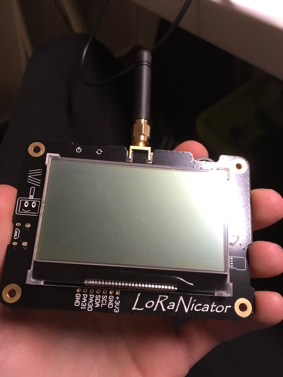
Successfully tested the display. Also ordered a different type of On/Off-controller, which expects a feedback from microcontroller within >10 seconds instead of 2 seconds.
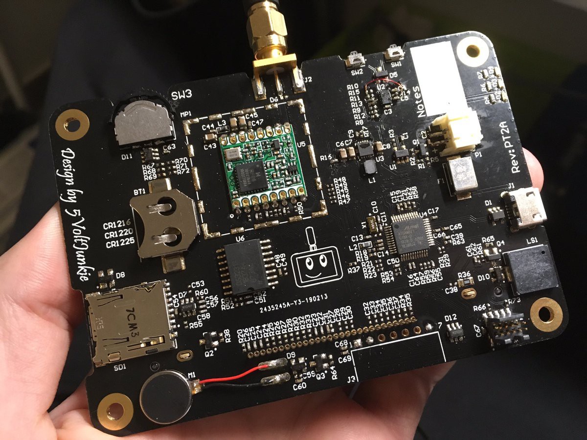
Started testing the hardware. Need another On/Off-controller since the current model allows only 2 seconds time frame for the feedback from microcontroller and the SAMD21 with Arduino bootloader needs ~2.5 seconds for booting and setting the GPIO to High.
Following initial tests passed (tested with example codes)
- RFM95 module
- I2C RTC (fixed a mistake in routing of I2C. SDA and SCL were swaped :( )
- uSD-card
- LiPo charger
- programming over USB
Next steps: - order some missing parts (capacitors for the display) - test display :-)
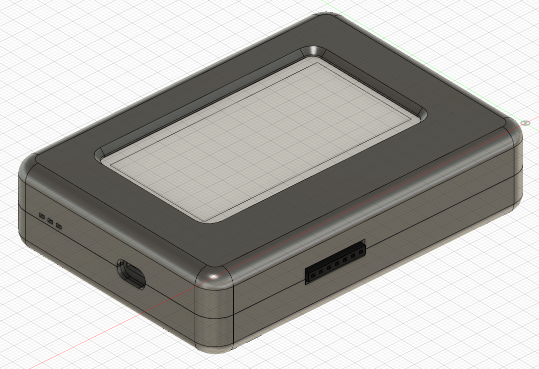
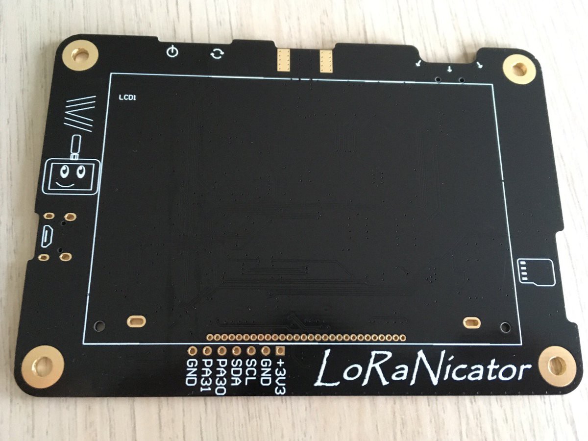
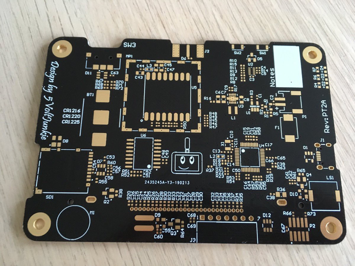
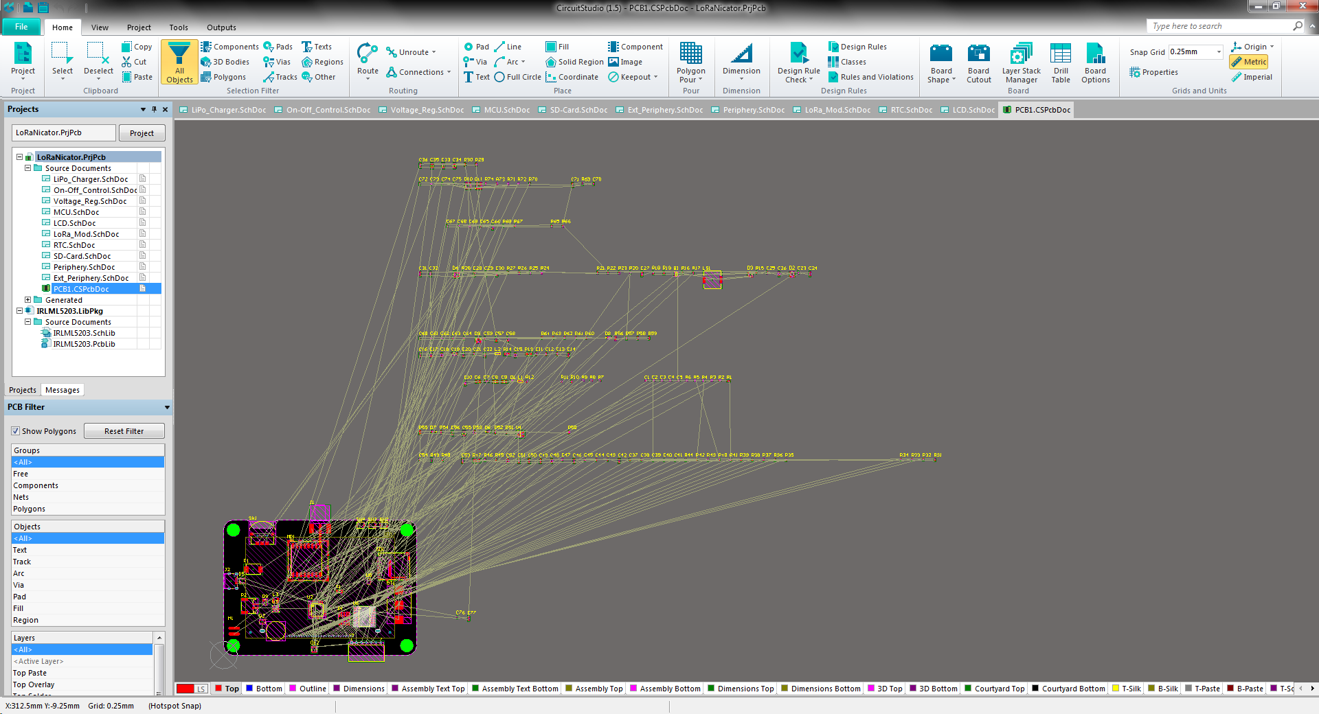
The schematic is almost done. Just need to add some information to part properties. Now I can start with the PCB design. The dimensions of the board will be about 100x70mm big (3.9x2.76inch). I already ordered a couple of components, because I had to create some libraries and it's also a good feeling to having some real components while working on the project :-)
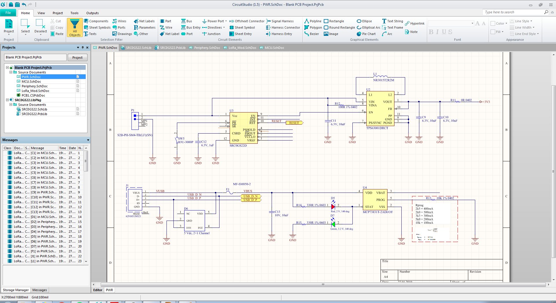
Started with the power management today. A couple of month ago, I found a very interesting ic from ST, the SRC0. It's a small on/off controller, which can be connected to a SMPS, so the power supply can be enabled / disabled by a simple press of the push-button. Furthermore it has an input for external signal, to disable the power (e.g. from microcontroller).
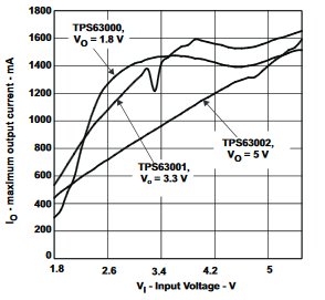
For the SMPS I would like to use the TI TPS63001 buck-boost converter. It provides a fixed +3,3V voltage output @ >1000mA current output (Vin = 2.6 - 4.2 VDC). In this voltage range and at ca. 100mA load, the efficiency stays >90%, which is not so bad :)
For the charging circuit I'll use MCP73831. The circuit will be powered by 1 LiPo cell.
After playing around with the first Prototype of LoPSy (LoRa Paging System ;-) ) and the first range test went well, I wanted to start with a new hardware revision.
The first hardware prototype contained a Nokia display, AI-Thinker Ra-02 433 MHz LoRa module and an ATmega328 µC.
For the new hardware revision I would like to replace the mentioned components and add few more functions.
Some requirements:
SMPS instead of linear regulator
1-cell LiPo charger IC
ATSAMD21 microcontroller (compatibility with Arduino Zero MKR (and Adafruit Feather?))
 5Volt-Junkie
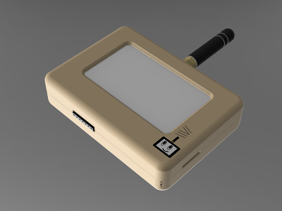
 In this voltage range and at ca. 100mA load, the efficiency stays >90%, which is not so bad :)