The mAtriX effect - But in person it looks nicer ;-)
JAWC - Just another Wordclock
Just another Wordclock with Arduino and WS2812B
Just another Wordclock with Arduino and WS2812B
To make the experience fit your profile, pick a username and tell us what interests you.
We found and based on your interests.
The mAtriX effect - But in person it looks nicer ;-)
WordClock_V3.inoArduino Code for the Wordclockino - 30.35 kB - 02/11/2019 at 20:38 |
|
Also almost done :) I just added all important steps to this Project :)
Please also find some additional Links here:
But google finds much more Websites :)
I hope you enjoyed these writeups.
Since i didn't want to use ordinary hardware buttons or switches i had to implement a little UART protocol to spreak with the Clock.
This was the easiest approach ==> Read every Byte from Serial port, if it matches one of those letters, do more special reading. I'm sorry I was a bit lazy with this. Maybe the proper way would have been to use a state machine or something. Most of these commands are more of the Backend and for Testing.
The general working of the clock is, that each Second an Interrupt occurs which increases the seconds. If the Seconds are >= 60, increase minutes, if the minutes are >= 60, increase the hours. If the hours are >= 12, increase the half days.
// This Timer is executed every second
void countSecond()
{
  mySeconds++;
  if(mySeconds >= 60)
  {
    mySeconds = 0; // mySeconds % 60;
    myMinutes++;

    if(myMinutes >= 60)
    {
      myMinutes = 0;
      myHours++;
      if(myHours >= 12)
      {
        myHours = 0;
        myHalfDays++;
      }
    }
  }
}
Btw: I noticed a notable deviation between a Stock Arduino board and my own board. The Arduino Uno lost almost 15 minutes a day :(... But fortunately my custom Arduino board does not do that.
In the meantime, in the main loop there is a check for the Serial communication and also a checker if another minute has passed. If a minute has passed, show the time on the clock.
So, around each minute there is an update of the time - depending on the minute and hour count.
I also spend another function to show a word on the clock. Since I used the
<Adafruit_NeoMatrix.h> and <Adafruit_NeoPixel.h> I used the filled rectangle function to fill all the words.
The Time is always shown in the selected color (White or the one which was set via serial).
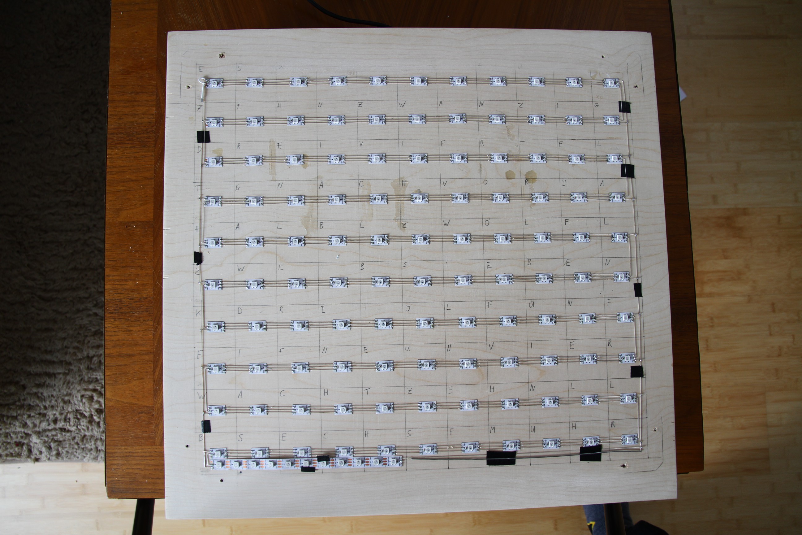
The LED Strip was laid out 11 times 10 pixels in Zigzag configuration.
I also added some special functions.
So i added these Commands:
* Available Commands:
* t .. Set the time by ""hh:mm:ss""
* d .. Enables / Disables DebugMode
* r .. Send the actual Time by Serial
* ? .. Send Help & Info by Serial
* k .. Display Circles
* h .. halt/continue the clock updating
* c .. Set up the Clock Color by ""RRRGGGBBB""
* l .. Show each Line of clock in clock color
* m .. Show tHe mAtriX
* x .. Clear Clock face
* f .. fill screen with clock color
* p .. print point ""xxyy"" (from 0)
* b .. set brightness (from 0 - 255)
* u .. shows the time once
* n .. shows the Rainbow
I think the description is really self explanatory. But maybe you might to know more about some commands:
h: This halts the updating of the clock - so the actual LEDs will stay on until you "unhalt" the clock. This is really useful to print points etc.
m: This is a nice matrix animation which cost me almost the most time. But for my taste it is really neat!
p: This is a function to only set the LED at the specified coordinate with the clockcolor. F.Ex. p0000 will light up the first LED of the first Row. p1009 will light up the last LED on the last row.
n: This is a function to just show a static color gradient on the clock:
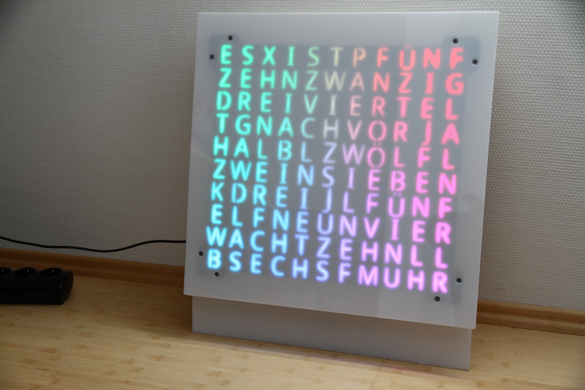
For Communication with the clock i prefered the
https://play.google.com/store/apps/details?id=de.kai_morich.serial_bluetooth_terminal
It's a amazing app. Maybe there are others or betters but i really liked this one.
As mentioned before i used the #Furious Tooth Fairy as control board. But as mentioned in that project it is only a standard Arduino setup + Bluetooth (HC5). I decided early on, that i don't wan't to have buttons or touch. I thought if it is mounted to the wall it would be much cooler to remote control the clock via Bluetooth.
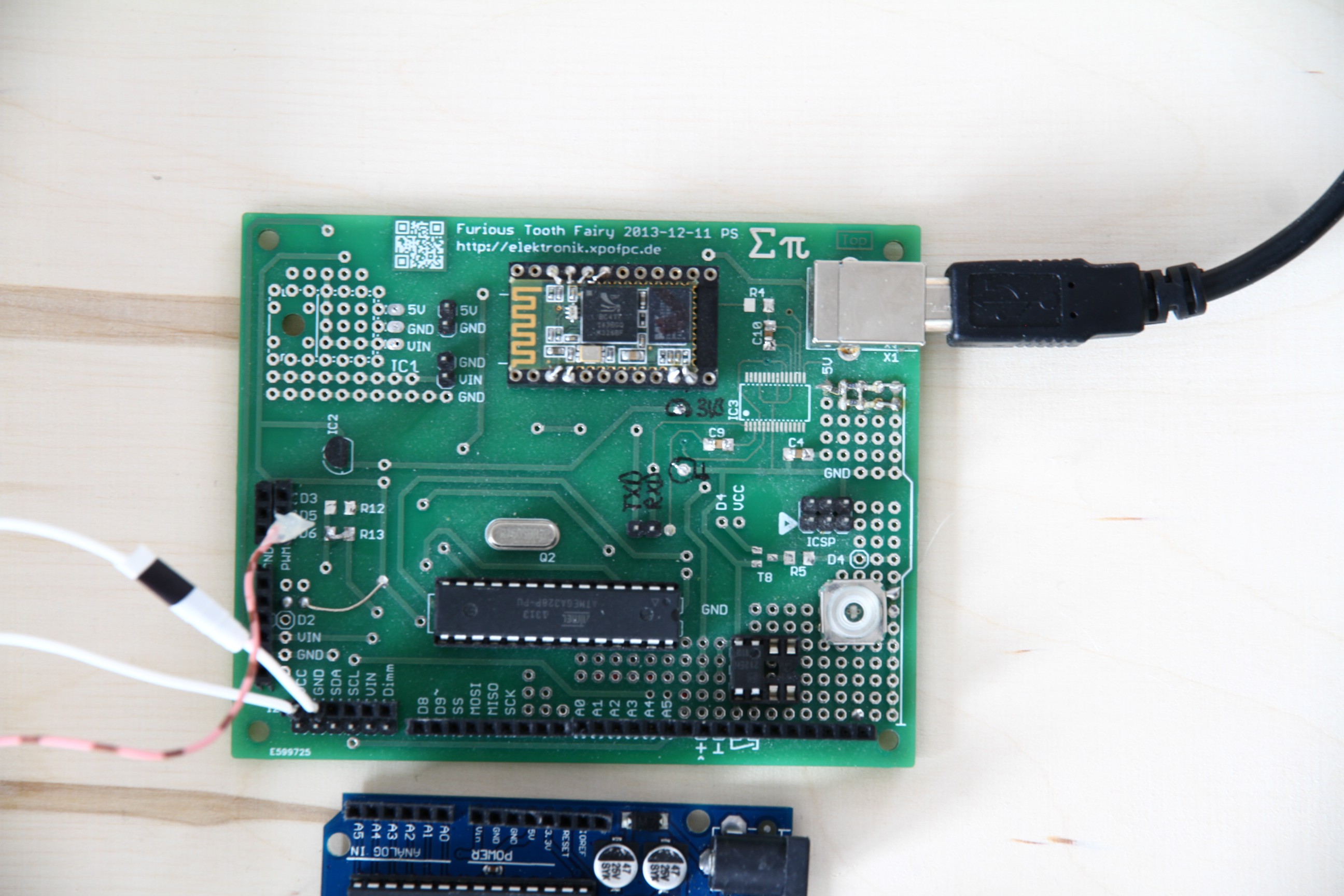
[As you can see the Board took some dust ... literaly]
This has also the Advantage, that there is no need for additional Hardware except for the BT Module.
I also thought about using some Wifi Stuff... but i still had these Boards on hand - and it is really easy to use a Bluetooth Terminal on a smartphone to control the Clock. On the #FTF there is a Voltageregulator for 3.3V, the Atmega, A switch, a Optocoupler, the BT Module and some pinheads. Also there are unpopulated Footprints for LM7805 and FT232RL.
BTW: Does somebody know how to utillize the FT232RL to programm an Arduino?
Edit: Mindblowingly easy: Just Bootload the Atmega once and connect the Reset via Capacitator to the FT232RL...
For first tests i used a Arduino Uno. So later i only needed to load the Software onto the Atmega328p and I'm ready to go. In the meantime i enjoyed the ease of Uploading via USB and the USB Terminal.
The WS2812 are just amazing ... i just realised i missed them my whole live :-D
You need only one Pin to control up to *a huge amount* of LEDs. In this project i control 110 effordless.
In the next Log i will tell a bit about the programming.
In parallel to the printing i was able to create the LED Matrix.
Unfortunately the LED distance did not match my Expectations...

So i did the labourious way: connect the LEDs with silver wire. I had a template to place the LED Strips pieces. Afterwards the LED pieces are connected in ZigZag Mode. I connected all Ground to one Side and all Plus on one side.
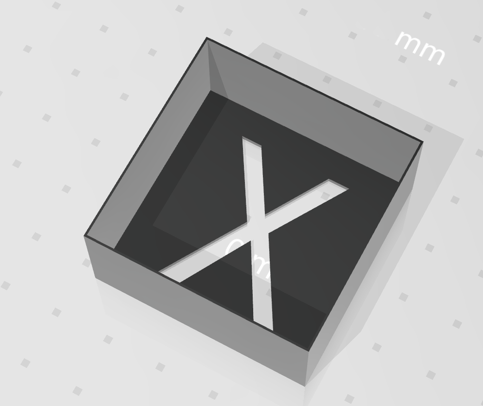
As i don't own some sort of cutter i just went with 3D Printing. I will probably add the Letters to Thingieverse so you can do that (PITA) to yourself :-D
Since i wanted to have the Clock like half a meter wide each Letterbox has a outer dimension of 40x40x20mm. Nine pieces took about 1.5h to print (Yepp ~ 20h of Printing, but not that hard).
In Retrospect i would not recommend to print each Box seperately. Maybe you can combine some Boxes at the Slicer so it would be easier to combine.
If your printer is Big enough you can also just print all at once ^^.
I did it the labourious way - glue each box to the next one. One by One, Row by Row.
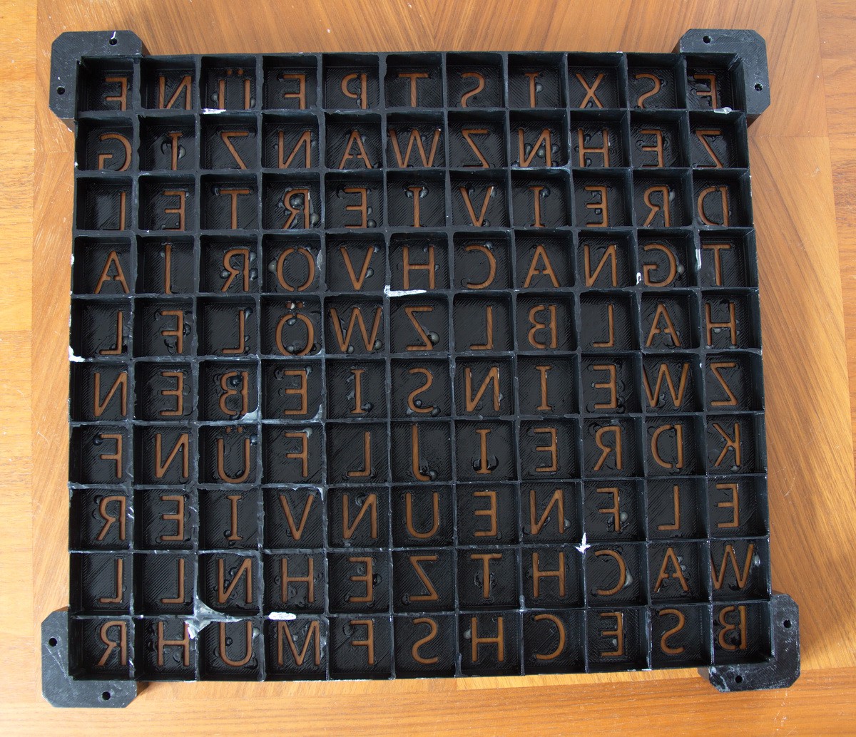 As you can See the Backside has some issues ... blobs of XTC 3D and some pieces of the underlaying Material. Nothing to bad - since not visible.
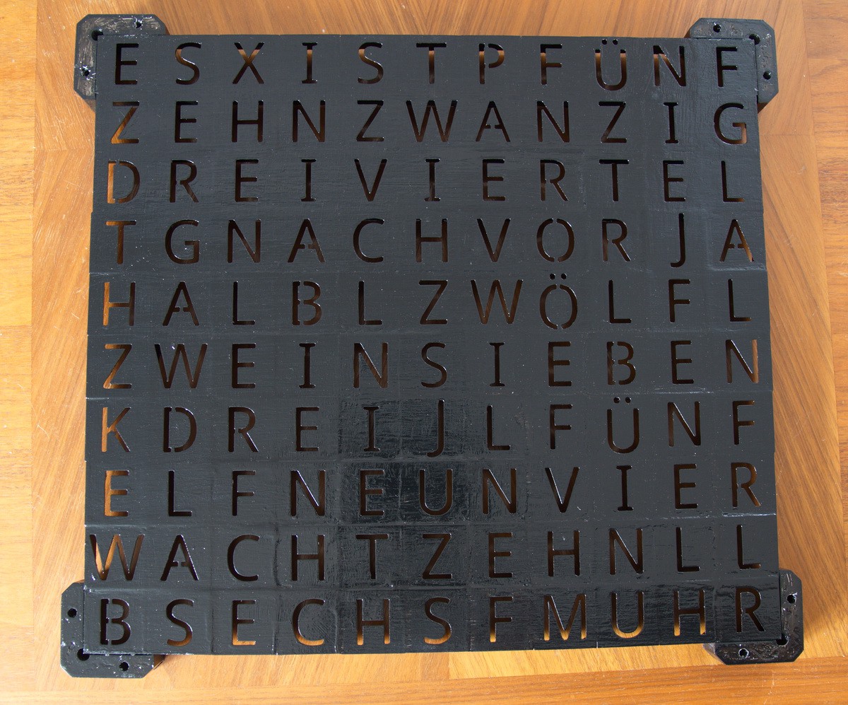
After that i added some layers of Black Paint and XTC 3D to the Clockface. Originally i planned to use it as visible Part. But the Finish of the other side did not meet my expectations.
Maybe some more Painting and sanding? But the solution is also really enjoyable. But Later more.
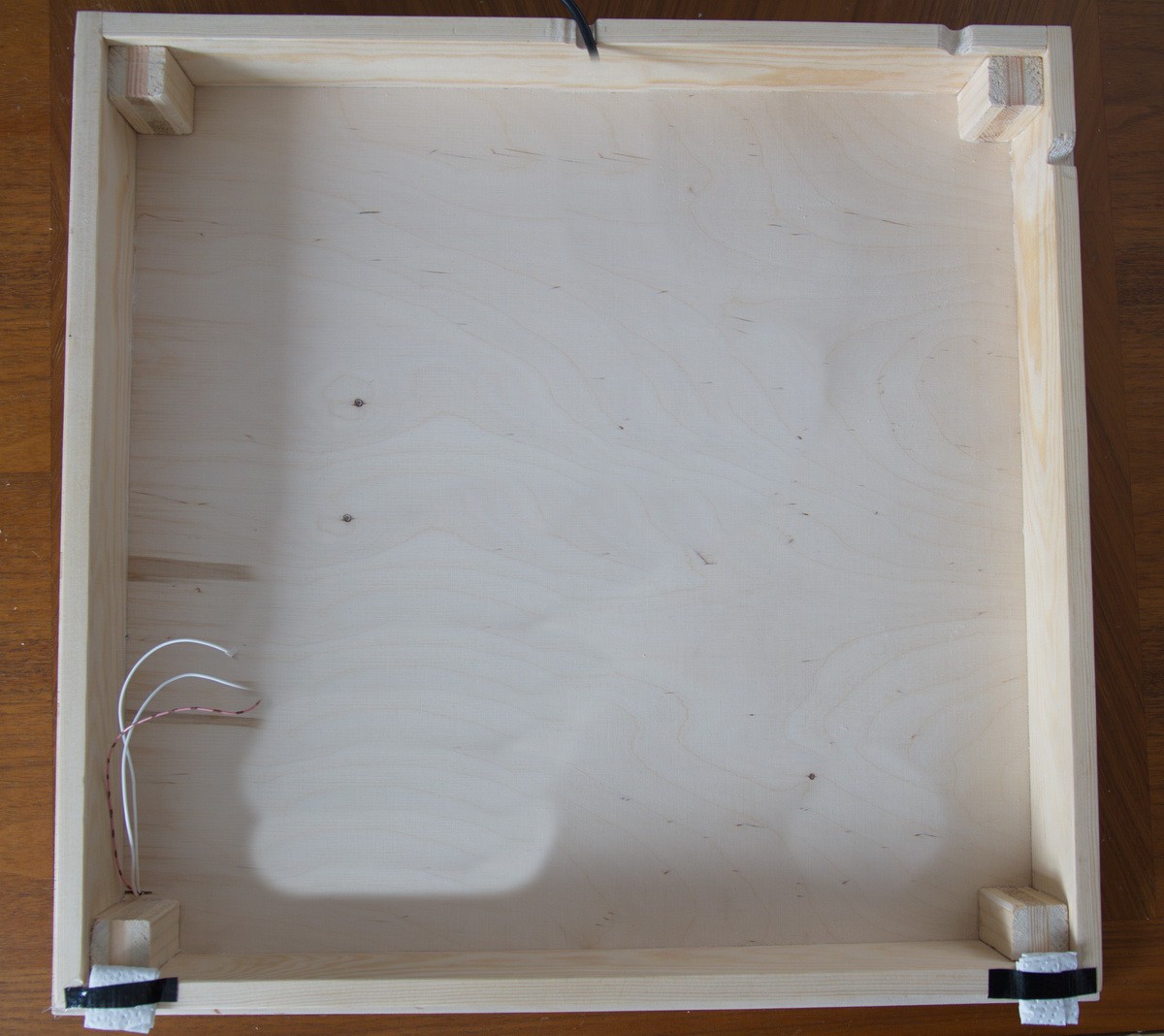
The next step is to create a Frame for storing the electronics. I just put 4 pieces in a rectangle and glued them together. In the corners there are some Wooden "Blocks" for more stability.
Additional i milled some Notches to feed a cable through. on the bottom in this picture there are the hooks to gang it against a wall.
I first thought about using a 5mm Plywood but it was not sturdy enough and i upgraded to 15mm (Since it was available from the left over pieces at the Hardwarestore).
In this picture i removed the Electronics to not spoil your reading experience ;-)
But there are already the cables visible: 5V, GND and Data In.
First step is to design the Clock Face. In best case you find one on the Internet matching to your desired Language. In my Case i borrowed a German Clock Face (First German Google Result).
But just think a moment about it. There are some Letters which are not needed to display Time, so you can define your own Letters between. Here i took some Colors to the Clock face:
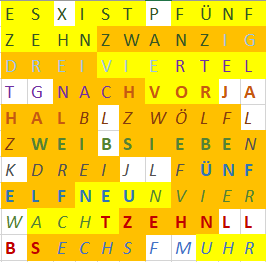
I used EXCEL to do this ... but I'm sure Open Office Calc or simmilar will also do the Trick.
Next i created a Template with marking of the center of each letter.
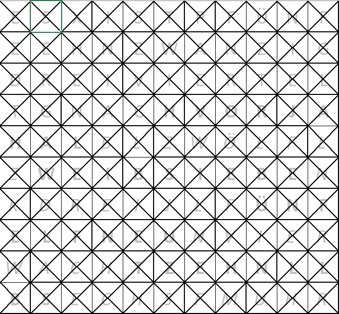 This template is going to be transfered to the Wooden Sheet.
Create an account to leave a comment. Already have an account? Log In.
Looks great.
I'm curious what the additional piece of led-strip at the bottom is for.
Hehe thank you :)
For this see Log 4. ;) "On the Bottom there are additional 10 LEDs for spare."
I thought i add them there, so if some LEDs fail after a while, i could take one off of them to replace.
Sorry; I must have overlooked that. Great idea. That way, when you have to replace them, they are from the same batch. So you're less likely to have a color or brightness mis-match.
Become a member to follow this project and never miss any updates
 mircemk
 davedarko
 Simon
Simon
 Andrew Cooney
Great design!