 Chris
Chris-
1Print / purchase gear train components
STLs for the planetary gear sets and assorted mounts are all available on Thingiverse. In all, the camera mount contains:
Part Quantity 5 : 1 planet gear 16 5 : 1 sun gear (motor shaft axle) 1 5 : 1 sun gear (carrier shaft axle) 3 5 : 1 ring gear 3 5 : 1 ring gear with tripod mount wings 1 5 : 1 planetary carrier 4 Motor mount retainer 1 Inter-set retainer 5 4 : 1 planet gear 8 4 : 1 sun gear 2 4 : 1 ring gear 2 4 : 1 planetary carrier (one normal, one "camera mount") 2 Final retainer plate with cutout for camera ball head 1 Tripod mount 1 In addition to the printed parts the gear train contains the following hardware:
- The planetary carriers each use four M4 hex head screws, 6mm in length, for a total of 24 screws
- Four M3 screws or threaded rods 80mm in length. If you're using threaded rods, get some M3 lock nuts to put on the rod end in place of screw heads.
- Four small M3 screws (5 or 6mm) for attaching the stepper motor to the mount
- Four 15mm M3 screws and four M3 nuts for attaching the assembly to the tripod mount
- A camera attachment ball head. The ball head lets you point the camera mount due north and adjust the camera independently. I purchased this one from Amazon.
-
2Assemble the motor mount and first stage
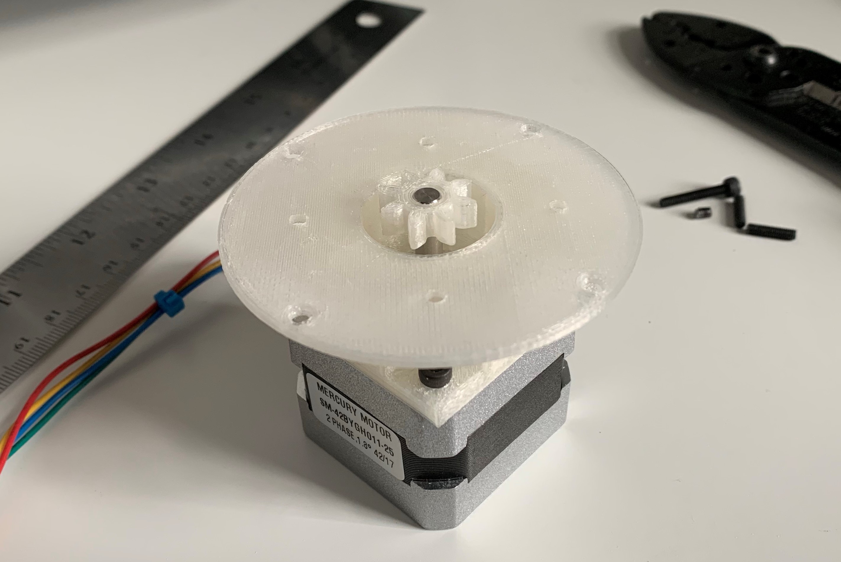
Set the motor mount retainer on top of the stepper motor and attach with 4 x M3 screws. Press-fit the 5 : 1 sun gear with the motor shaft axle to the stepper motor shaft.
![]()
(note: the motor mount STL doesn't have the four holes in the plate right above the screws - I ended up drilling those so I could get a hex wrench into the screws)
Next, arrange a set of four 5 : 1 planetary gears around the sun gear. Put four of the M4 hex head screws into a 5 : 1 planetary carrier and set it over the planetary gears.
![]()
![]()
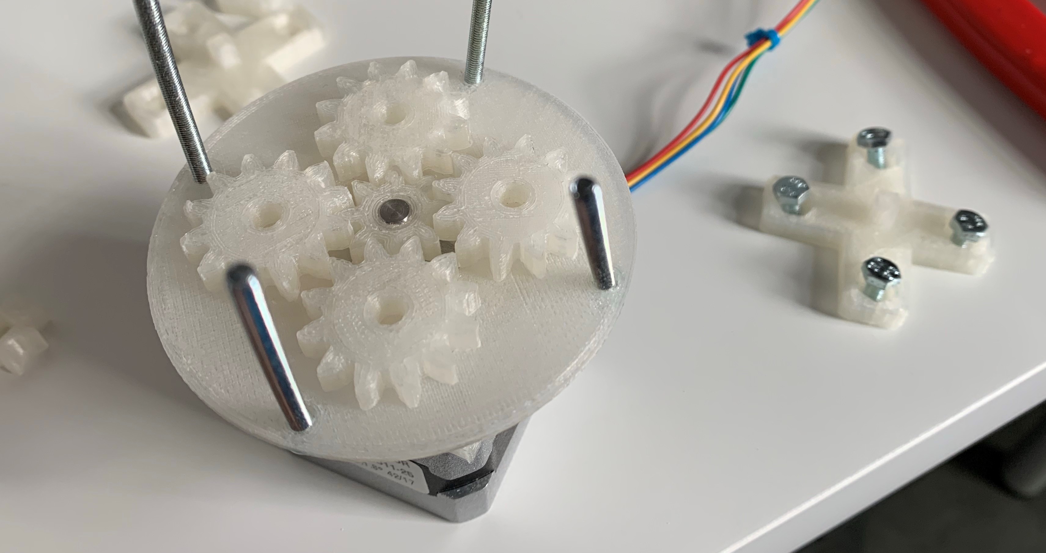
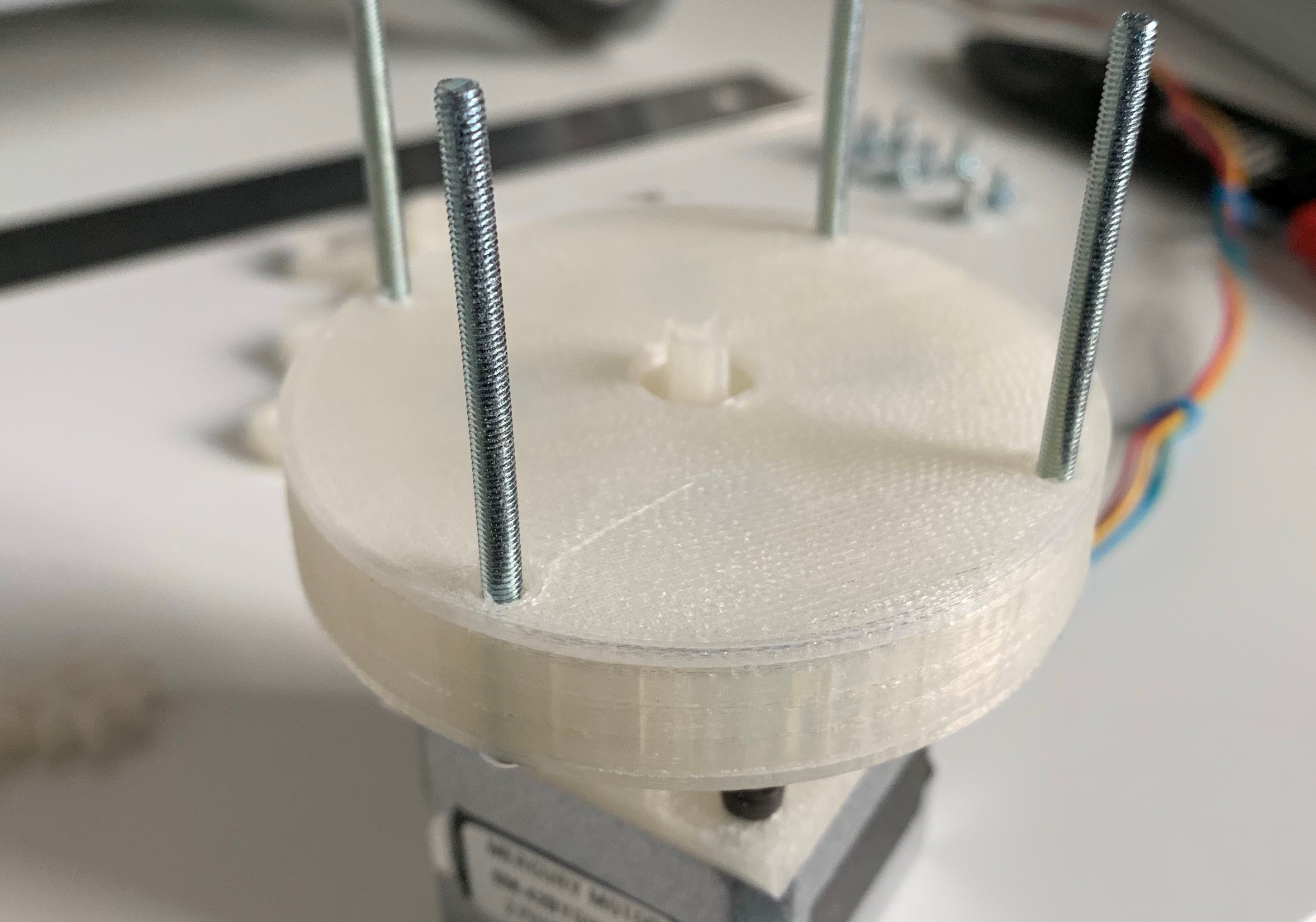
Start threading the M3 screws/rods up through the holes in the motor mount retainer. It actually turns out to be sort of difficult to thread them all the way through and then slide components down over them - the gears aren't solidly retained yet and can easily go all over the place. It is easier to only thread them up just through the components that have been placed, enough to correctly position the next piece.
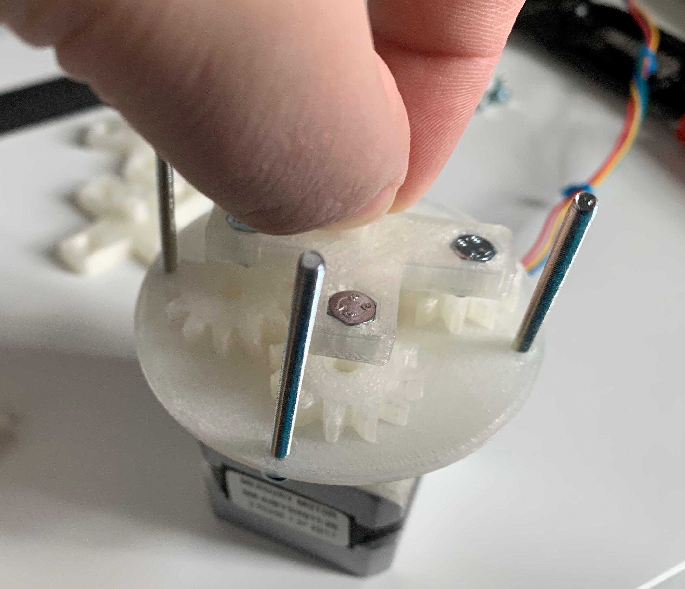
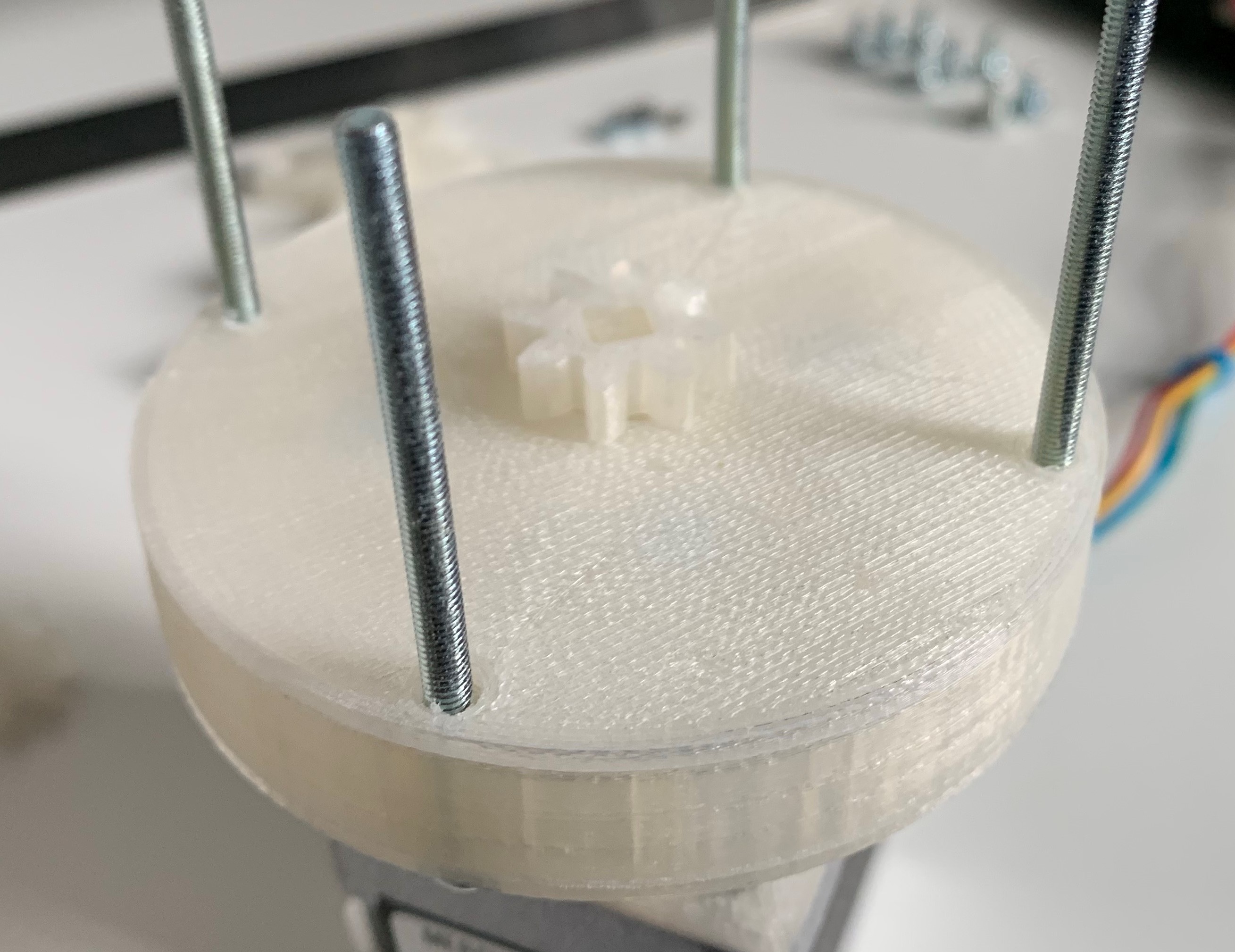
Set a 5 : 1 ring gear down over the planet gears and thread the rods up through it. This may require a little poking at the planets to get all the teeth in the right place. Set an inter-set retainer on top of the ring gear and thread the rods up through it. Press-fit a 5 : 1 sun gear (carrier shaft axle) onto the planetary carrier shaft.
![]()
![]()
![]()
And the first stage is done! There is now a 5 : 1 reduction from the stepper motor - for every rotation of the stepper, the planetary carrier and thus the next stage's sun gear will rotate 0.20 RPM.
-
3Assemble the remaining three 5 : 1 stages
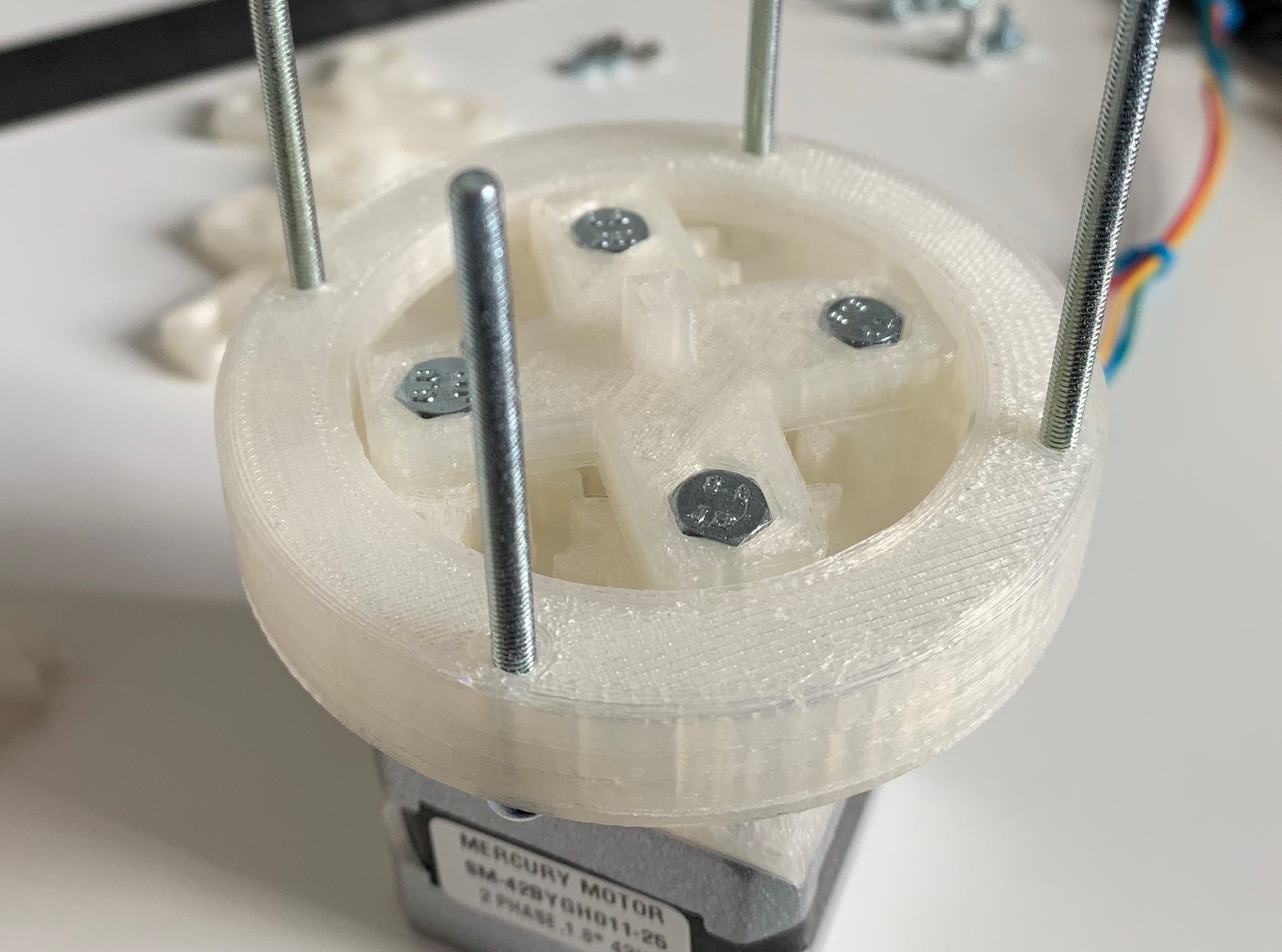
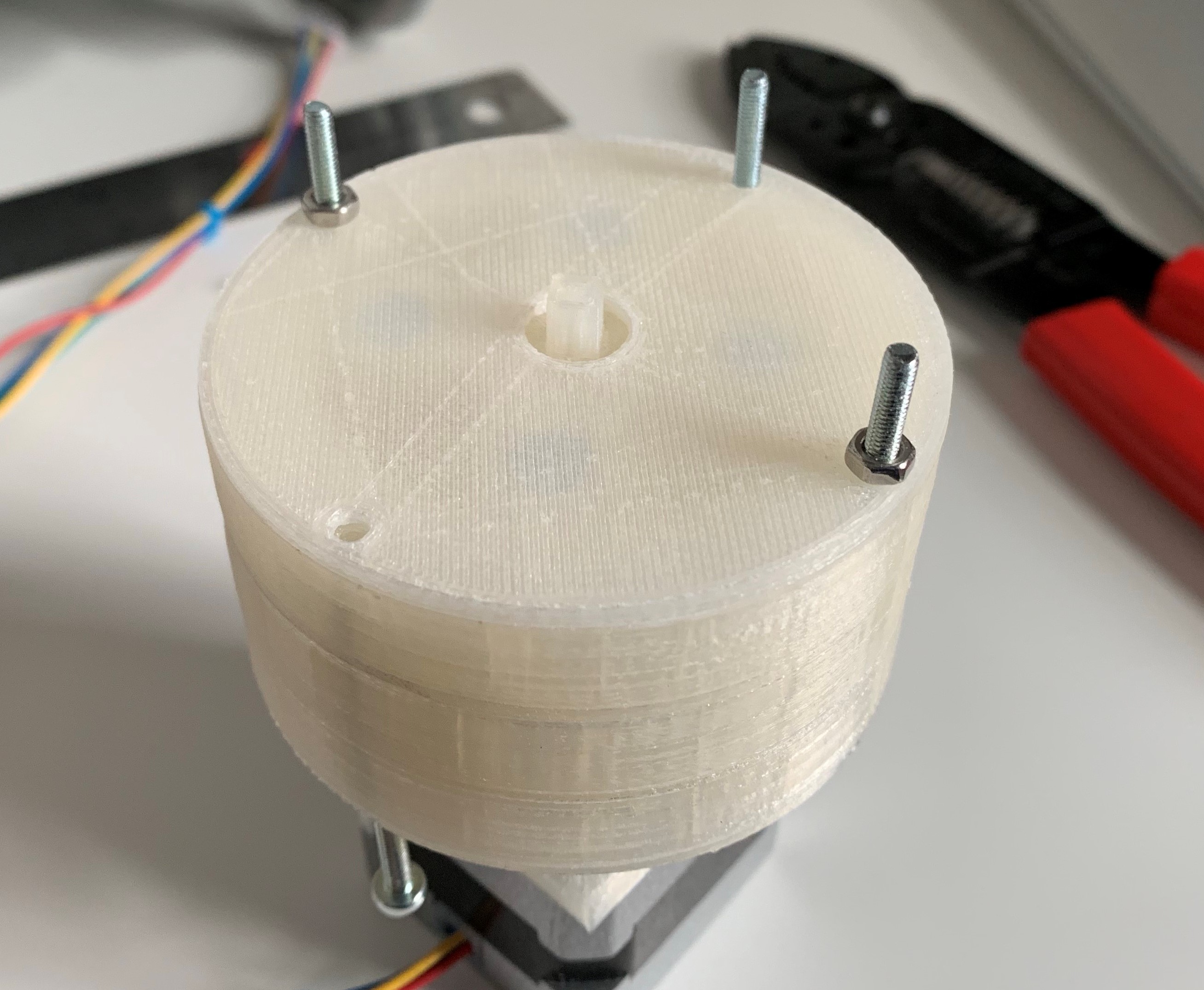
Repeat build step 2 for the remaining three 5 : 1 stages. If at any point you need to stop I strongly recommend using some M3 nuts to fasten down the threaded rods at the last completed piece. Tipping this over and having to re-place dozens of gears is not fun.
![]()
For the fourth and final 5 : 1 stage, use the 5 : 1 ring gear with the tripod mounting wings. It doesn't matter which direction the wings are pointing. After the retainer is on the last 5 : 1 stage, press-fit a 4 : 1 sun gear on the planetary carrier shaft.
-
4Assemble the final two stages and the tripod mount
Assemble the first 4 : 1 stage in the same way as the 5 : 1 stages: arrange four 4 : 1 planet gears, place the 4 : 1 planetary carrier, set a 4 : 1 ring over the planets, set a retainer on top, and press-fit the last 4 : 1 sun gear on the carrier shaft.
![]()
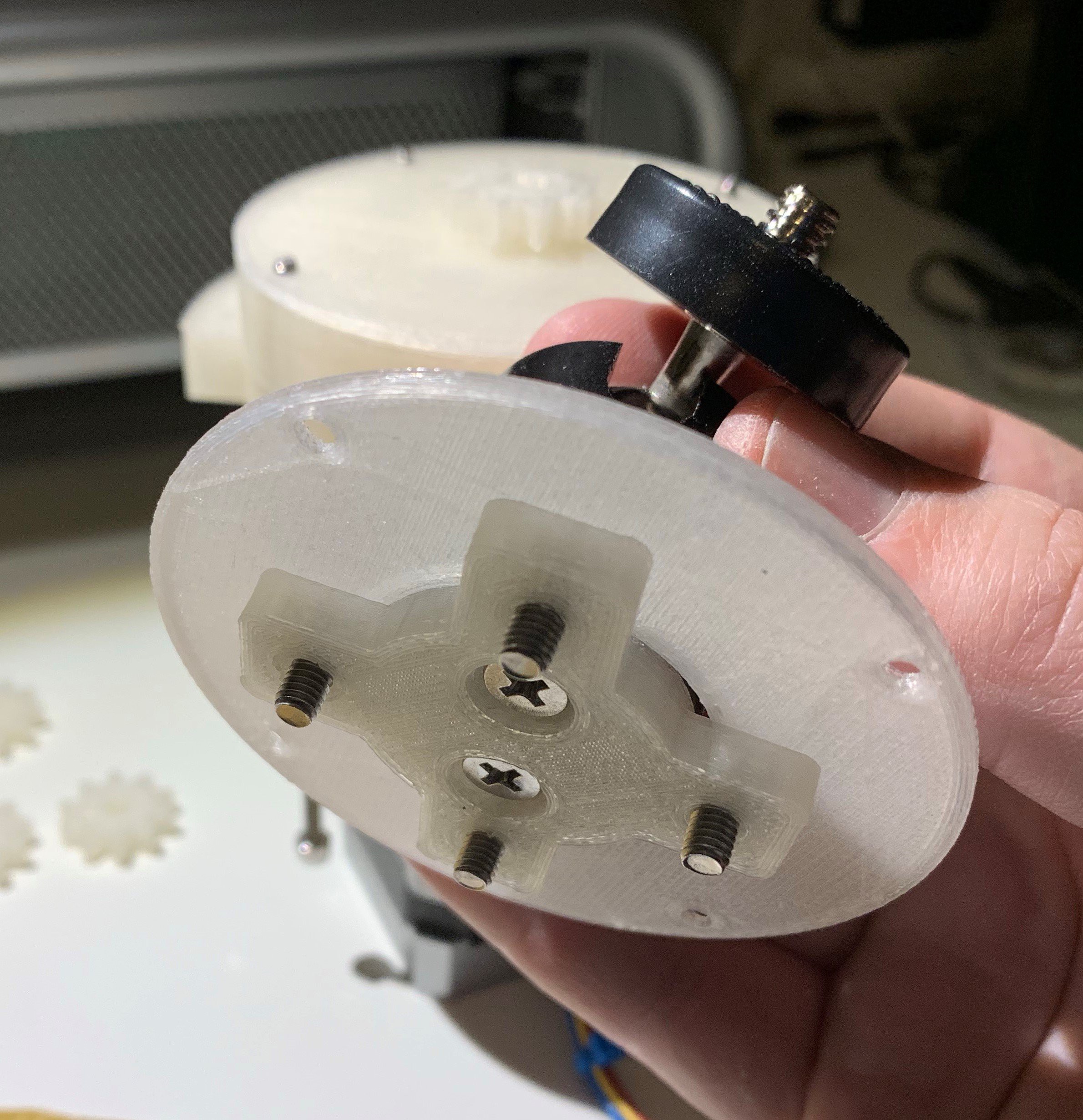
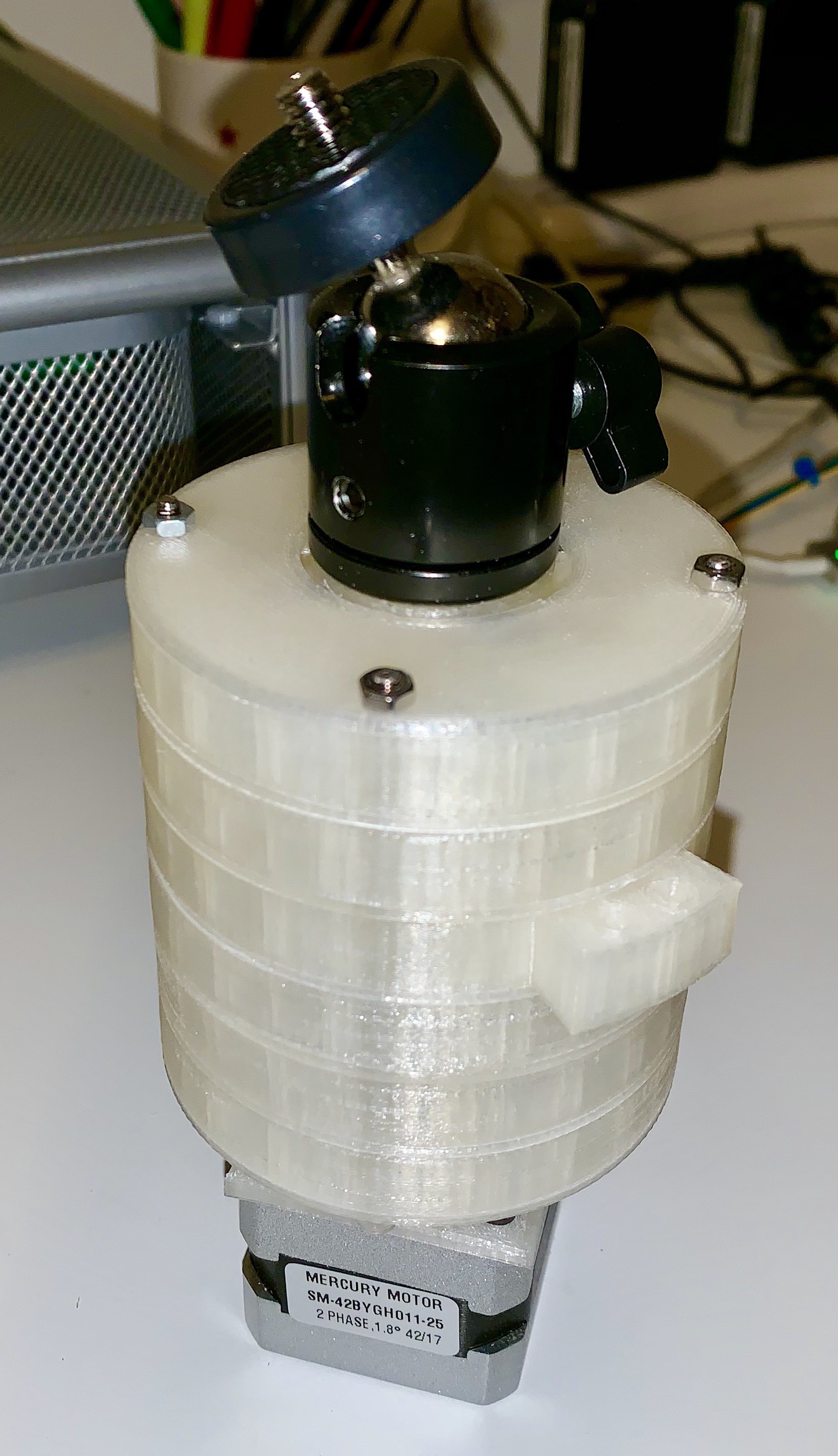
The last 4 : 1 stage is also the stage to which the camera is mounted. Before placing the last gears the camera mount carrier needs to be assembled.. Set the final retainer plate around the central cylinder of the camera mount carrier, then use two M4 screws to attach the camera ball head.
![]()
Once the carrier is ready, place the last 4 : 1 planet gears and place the carrier over them. Set the final 4 : 1 ring gear over the planets and secure the final camera retainer plate over the entire thing. Use four M3 nuts to secure the threaded rods in place and tighten the whole thing down.
![]()
The final step in the gearset assembly is to attach the tripod mount. Slide the tripod mount over the mounting wings and fasten it in place with four M3 screws and nuts.
![]()
And that's it for the gearset assembly!
-
5Attaching the mount to a camera
I believe that I've overengineered the attachments and potential failure points but attaching an expensive camera to a homemade mount for the first time is nervewracking. I've dropped and cracked lens before and it isn't a good feeling. Perform this step a few inches over a soft surface! I cannot be responsible for damaged equipment but that doesn't mean I wouldn't feel terrible.
Straighten out the camera ball head along the axis of the mount and tighten it down. Holding the camera in one hand and the mount in the other, line the ball head's screw up with the camera's attachment port and turn the mount until the ball head screw is in as firmly as it can go. Spin the adjustment disc on the ball head to snug up the fit.
![]()
-
6Do not drop the mount with a camera attached
Don't drop it.
Not pictured: dropping it
-
7Set mount onto tripod
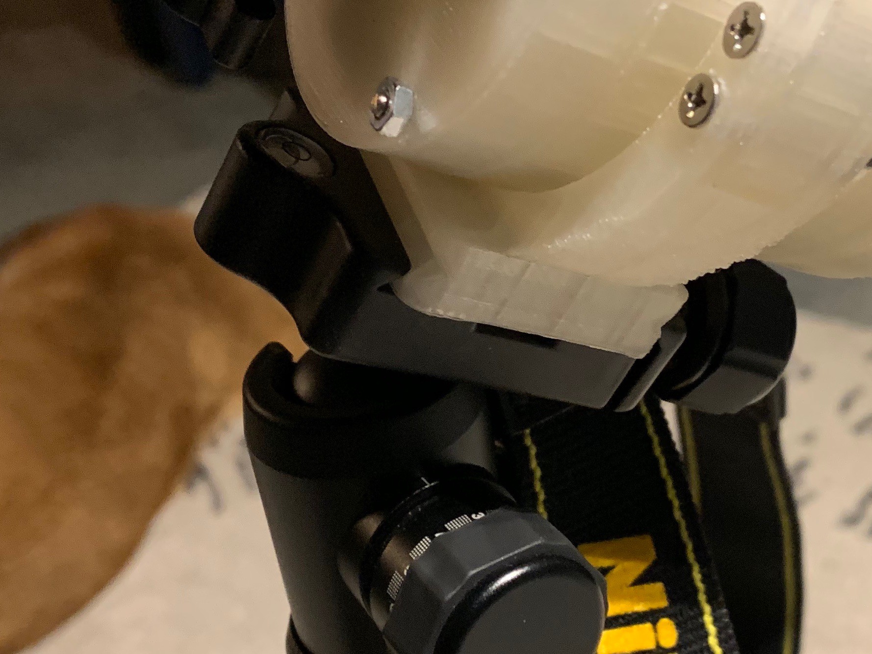
The tripod mount was modeled specifically for my tripod, a MeFOTO A0350 with an Arca-type quick release plate. Unscrew the plate clamp to its fullest extent, set the mount's foot into the plate, and screw it back down.
![]()
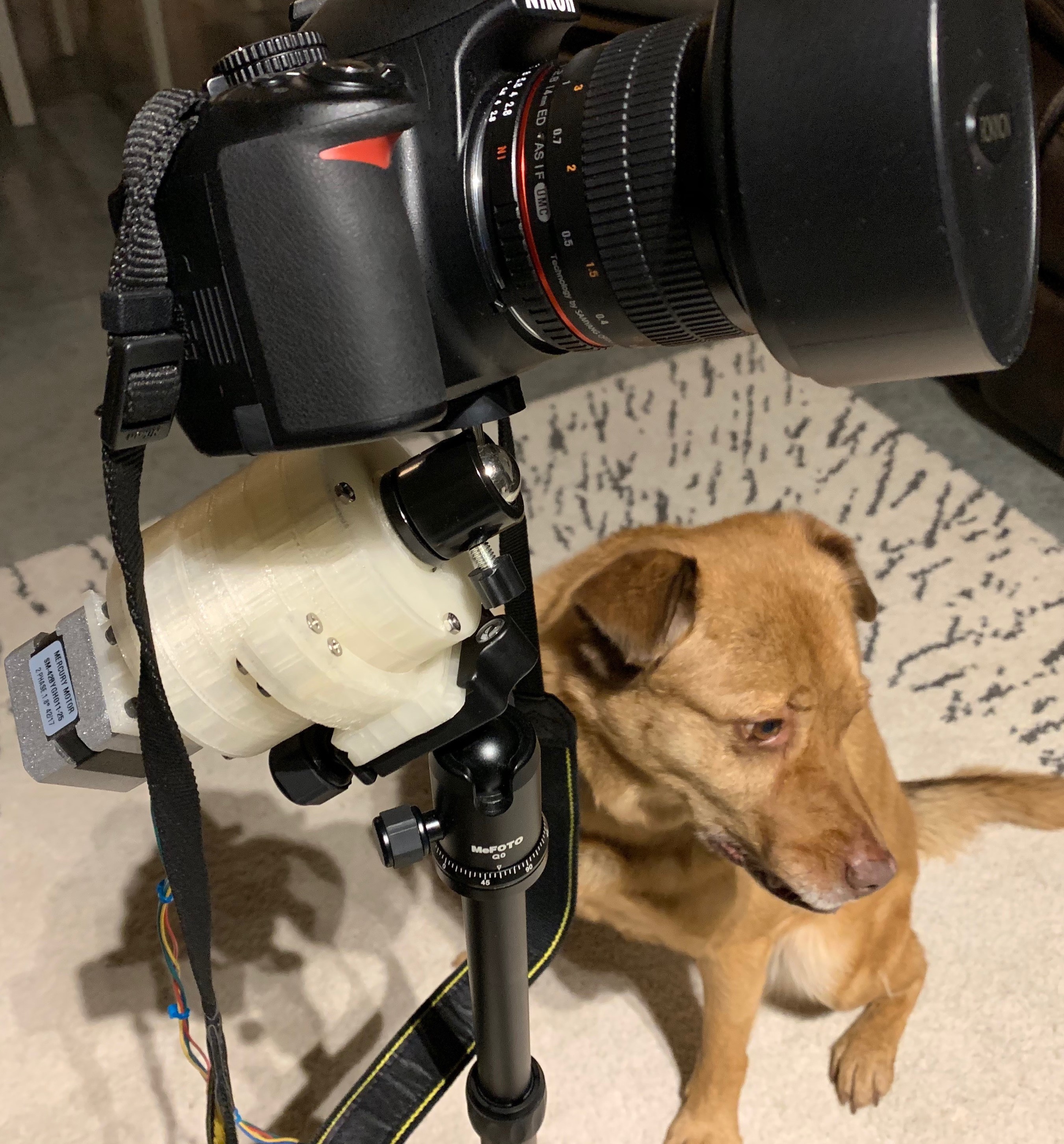
Full view of the entire assembly on tripod. Unfortunately we'll have to imagine this outdoors at night as it's raining pretty hard right now.
![]()
Astrophotography Camera Mount
A 3D-printed 10000 : 1 gear reducer and control hardware used for astrophotography


Discussions
Become a Hackaday.io Member
Create an account to leave a comment. Already have an account? Log In.