Chris
Chris-
2020 Update: No New Photos, But New Ideas
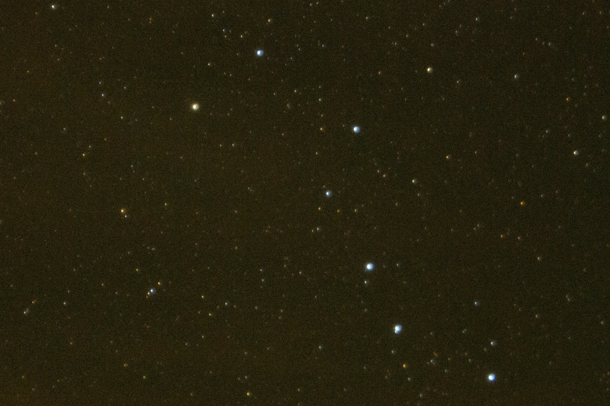
11/02/2020 at 03:24 • 0 commentsIt has been a quiet *checks dates* eighteen months on this project, and I apologize for not having more updates. The short story is that there are no new starfield updates on this project. 2020 has not been a great year for my family - though we are fortunate and no one has gotten sick, knock on wood - and we haven't been able to go anywhere for stargazing. We did get out camping once in late September 2020 to the Mark Twain National Forest in Missouri but it wasn't good for starfields:
![]()
Nikon D3100, Rokinon f/2.8 14mm lens, 10s @ f/2.8, ISO 280
The moon, Jupiter, and Saturn were all lovely though!
Since we're between photography sessions I have done some maintenance work on the housing and mount to make sure they're still working, and I've had some thoughts on what I want to improve on the existing system.
The Camera Attachment
The camera attachment ball head that the project is using works okay but it has two main issues. First, it's difficult to screw the camera body to the ball head while the camera aimer is on the tripod. Doing it in the dark and with a large lens on the camera makes it even harder, and I am constantly feeling like I'm going to drop the camera while getting it attached. Second, once the camera is attached, it has a fairly small range of freedom. The barrel of the camera aimer must be pointed straight north to cancel out the sidereal rotation so in order to take pictures of anything except Ursa Minor the camera has to be pointed independently without moving the aimer. The specific ball head that I'm using simply doesn't have a lot of ability to freely point the camera without loosening the mounting screw. I don't know what to do about this but I've been keeping an eye out for a better solution.
The Gearing Arrangement
Portability is important to me when I go camping and hiking, and the existing gear arrangement is neither light nor small. In some ways that's just kind of how it goes with a 10000 : 1 reduction - it's hard to accomplish that kind of ratio without a lot of gears - but I think I can do better.
- I plan to experiment with M3 or M2.5 sized hardware in the planetary gear trains to reduce the weight of the 24 M4 bolts. They function as axles which transfer the rotation from the planet gears to the carrier so I can't go too small but I can probably go smaller than 4mm.
- In addition to reducing the diameter of the hardware I plan to transition away from bolts entirely and go with pins. The gear sets are already tightly sandwiched so there is no real need for the bolt heads to keep the planet carrier in place.
- Each of the gear sets is 10mm thick for a total of 60mm (plus the retainer layers adding a bit more). It was sized that way because the bolt heads needed to be buried in the planetary carrier which made the carrier 5mm deep, and I just made the gears 5mm deep too. That is just overkill and I would like to reduce the height of the gears and carriers since I'm going to do away with the bolts that drove the requirement.
Is it foolish to make Mk2 when I haven't proved out Mk1? Mmmm...nope!
-
An Instructive Failure
04/30/2019 at 16:56 • 0 commentsIn early April my wife and I took a several day camping trip to Caprocks Canyon in north Texas. The weather was gorgeous (especially compared to Kansas City at the same time), the moon was new, and the evenings were mostly clear. Perfect for astrophotography!
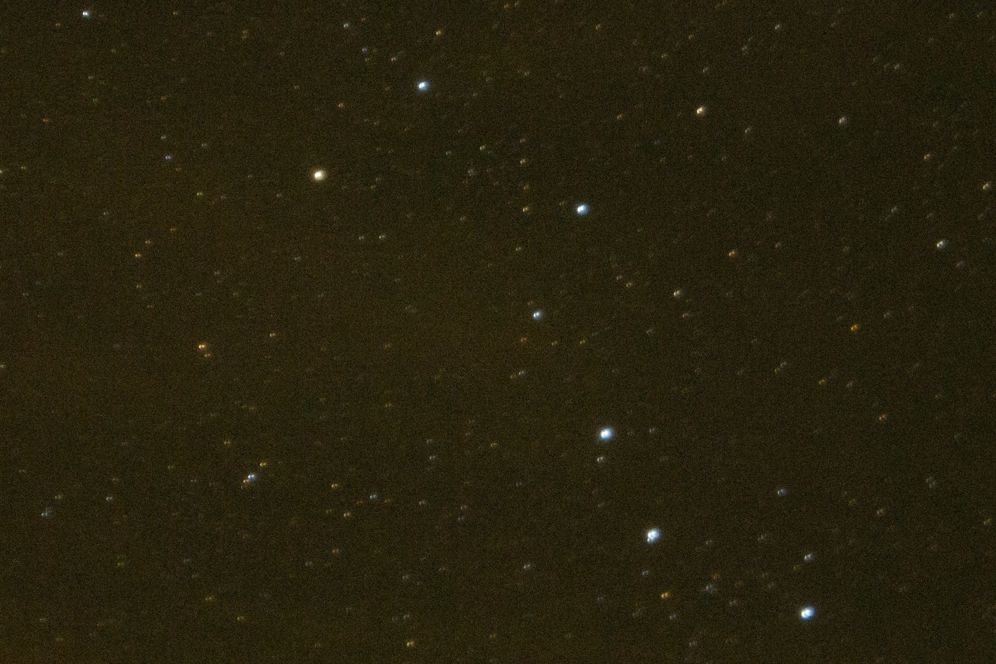
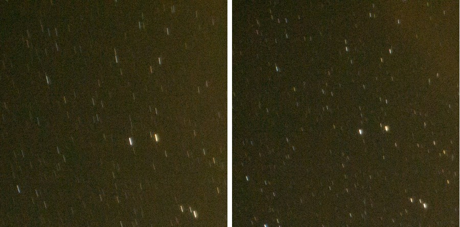
Below is an A/B comparison shot of a section of the northern sky centering on Ursa Minor. The camera was attached to the motor mount and the rig was set on the tripod then manually aligned with Polaris (leftmost star in Ursa Minor in this view). All pictures were taken with the same equipment: Nikon D3100 camera, Rokinon F/2.8 14mm lens. The sky was slightly cloudy and partially reflected the orange cast of nearby campfires. The images are cropped / resized in Lightroom and GIMP to show detail but not otherwise adjusted.
Ursa Minor - 25 second exposure, ISO 3200
![]()
No rotation
![]()
Rotation engaged
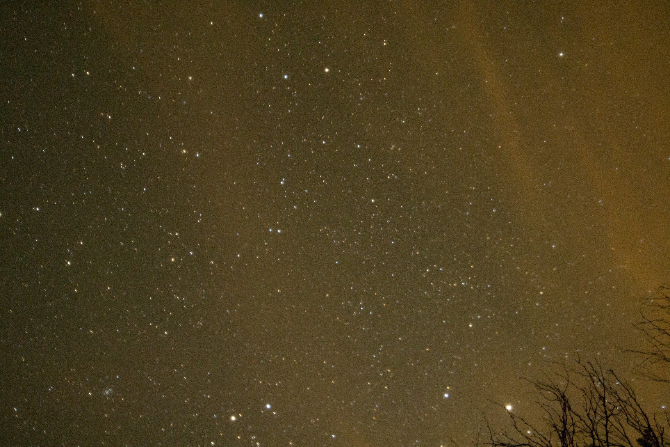
Manual alignment on Polaris aside, the "rotation engaged" image is more blurry than the image without rotation engaged. This level of blur wasn't visible to me on the camera's LCD.Here's another A/B shot, this time of the western sky with the same tripod position / alignment and a longer exposure.
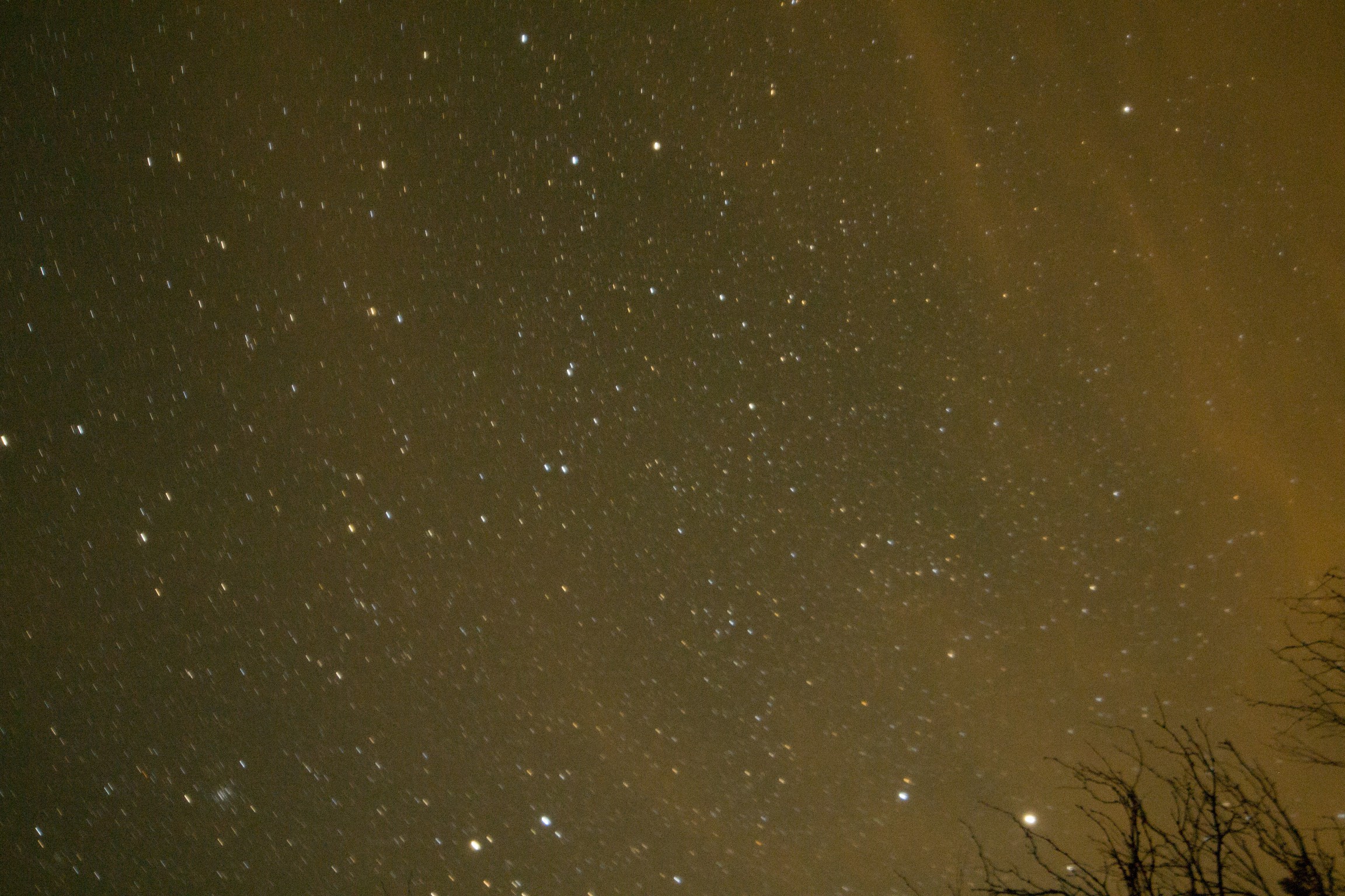
Western Sky - 60 second exposure, ISO 3200![]()
No rotation
![]()
Rotation engaged
And now an exclusive picture of me as I proofed the images after we returned home:![]()
Zooming in on the left side of the western sky photos shows that the star trails with the camera mount rotation engaged are definitely much longer. In fact the arcs are to the tune of two times longer.
![]()
Rotation engaged on the left, no rotation on the right.
The motor rotation was turning the wrong way for the northern hemisphere. I made the simple mistake of setting the A3967's DIR pin for "counterclockwise" by looking down at the motor mount from above instead of looking at the sky along the axis of rotation. The result was that the camera was actually turning with the rotation of the Earth and not opposite it, and so doubled the apparent motion of the stars instead of eliminating it.
Well, that's experimentation for you! Aside from the obvious firmware change to swap the directions I'm also taking the time to make some changes to the PCB design to add more control from the MCU to the motor driver and validate the camera shutter control circuit. We're planning a camping trip to the Colorado Rockies this summer which should provide another excellent opportunity for astrophotography and testing the mount. Stay tuned!
-
Testing the Gearbox
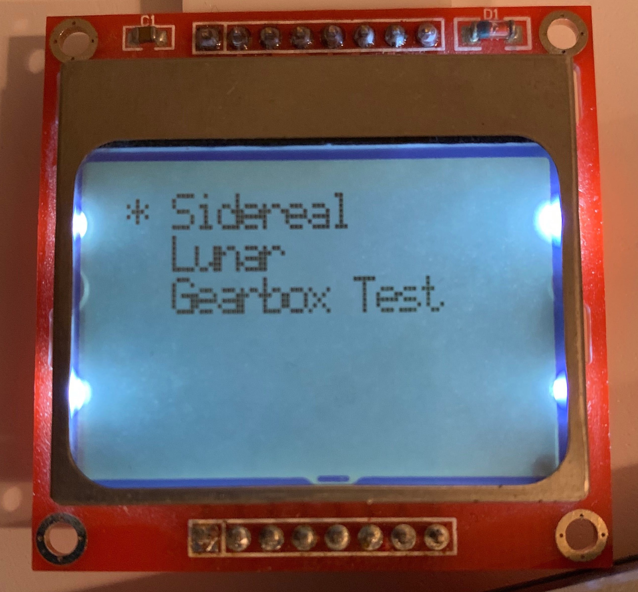
02/12/2019 at 03:52 • 0 commentsIn order to test the gearbox I decided to add a "Gearbox Test" speed to the firmware.
![]()
Driving at the normal rate could take a long time to make sure the last couple stages are moving at all. There's no reason they shouldn't be moving but that's the point of testing!
I encountered an unexpected problem though: driving the stepper any faster than a STEP pulse rate of 20KHz (which translates to roughly 80 RPM for a rate at the camera ball head of 0.008 RPM) and the stepper motor skips a lot of steps, enough so that it quickly stops moving altogether. The stepper driver's datasheet lists a minimum STEP pulse width of 1uS and we're well within that limit. What gives?
I believe the problem is that when it's being driven quickly there is not enough current is getting delivered to the stepper motor on each microstep. The A3967 driver looks for a variable resistance on REF to determine how much current to deliver to the stepper coils. This is by far the largest current consumer in the system and so the biggest dictator of potential battery life, which means that it is important to optimize for the lowest possible supply current while not sacrificing functionality. When I was prototyping a previous iteration of the project I used the EasyDriver's potentiometer to find the lowest supply current that would get the mount moving without skipping steps (~250mA) Problem is that I didn't recalculate the supply current in the current iteration, whoops!
There are two options:
- I can fiddle with the supply current by replacing R6 and R7 to change the voltage divider feeding REF but this board design can't deliver more than 3.3V at REF (should come out to about 400mA). If it turns out that more is needed I would have to do a board spin that divides down the 9V rail instead of the 3.3V rail.
- I can test each stage by running the stepper motor at the normal rate while the mount is disassembled and rebuild it, verifying that each successive stage does indeed rotate without "lurching".
I'm going with option 2. The last couple stages will indeed take a while to test but I'm not in any particular hurry, and not being in a hurry saves me money (no board spin) and effort (no redesign, no replacing the resistors).
-
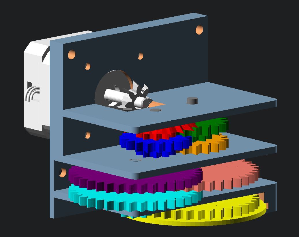
Cancelling Sidereal Rotation with a Stepper and a Lot of Gears
02/05/2019 at 01:58 • 0 commentsA stable long exposure shot in astrophotography requires cancelling out the sidereal rotation of the Earth. This is the rate at which the Earth rotates and is the reason for star trails. The idea is simple: if the Earth is rotating on its axis in one direction, rotate your camera on that same axis in the opposite direction at the same rate. Rotating on the same axis is easy. All you have to do is line up your mount's rotational axis to the North Star, Polaris, if you're in the northern hemisphere. If you're in the southern hemisphere there is a South Star, Sigma Octantis, but it is rather faint. Rotating in the opposite direction is also easy: counter-clockwise if you're in the northern hemisphere and clockwise if you're in the southern hemisphere.
The main problem is that the sidereal tracking rate is very very small. ASCOM Standards has it at 15.041 arcseconds per second. In more useful-to-me terms that comes out to a minuscule 0.00069634 RPM - a little less than seven-ten-thousandths of a rotation per minute! Driving a stepper motor that slowly would be choppy at best.
In order to get a final output of about 7/10000 RPM, this astrophotography mount gears down a stepper motor by 10000 : 1 using six planetary gearsets: four 5 : 1 sets and two 4 : 1 sets. This lets me drive the motor at a reasonable rate of speed (6.96 RPM).
-
MSP430 Controller Board
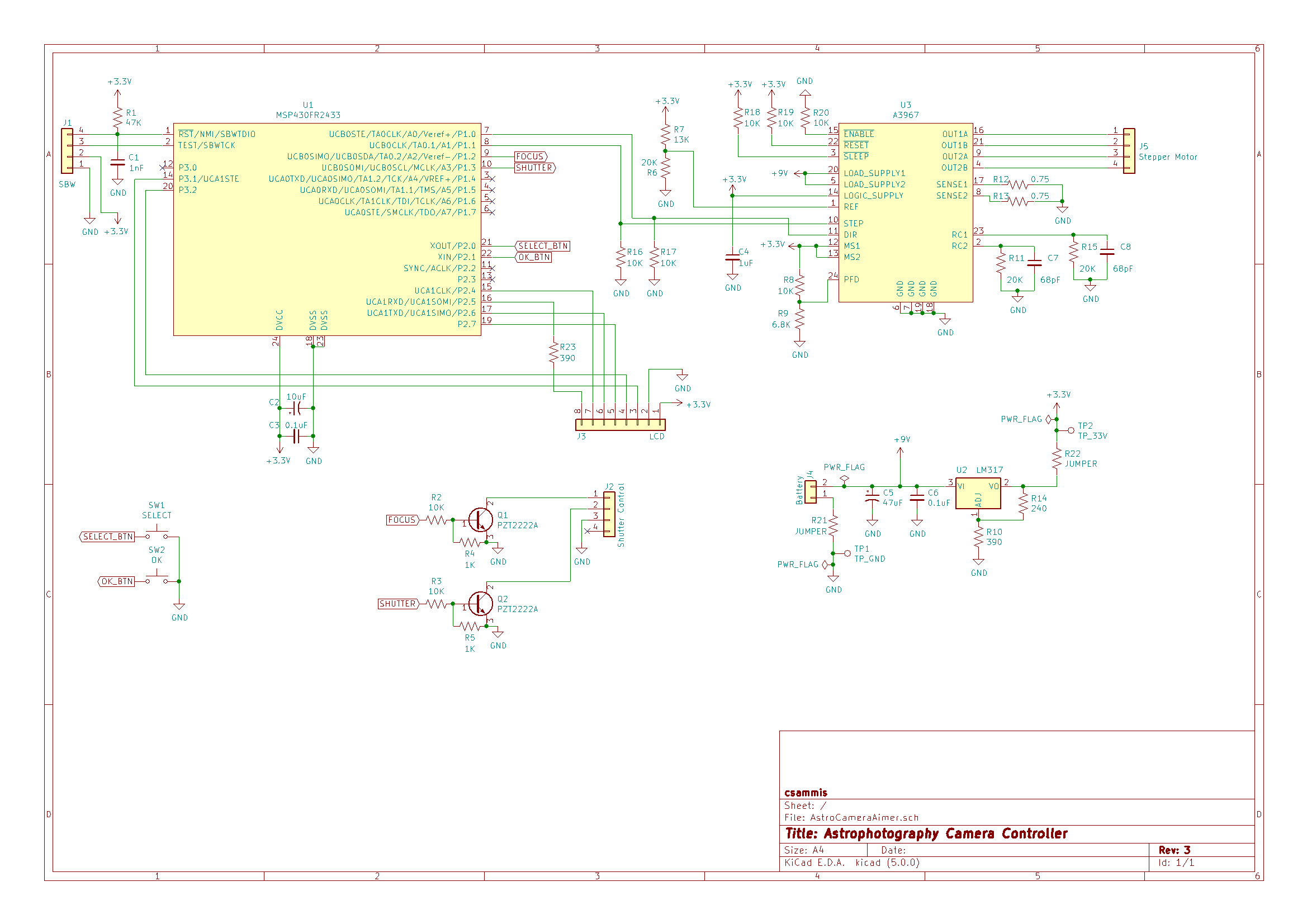
02/05/2019 at 01:16 • 0 commentsThe controller for this project is by far the most complicated thing I've personally designed. Schematic and board were built using KiCad 5 and fabbed at OSH Park.
![]()
There are a few major blocks:
- The host microcontroller is a Texas Instruments MSP430FR2433, chosen largely on the "that's what I have" principle.
- The stepper motor driver is an Allegro A3967. I prototyped this project using Brian Schmalz's excellent EasyDriver (purchased from Sparkfun) so the choice of IC was an easy one.
- The MCU takes its input from two pushbutton switches and outputs to a Nokia 5110 LCD (also purchased from Sparkfun) as well as a pair of transistors used to switch the camera's remote trigger - the remote trigger functionality is still untested though.
- The whole thing is powered from a 9V battery which feeds directly into the A3967 and supplies an LM317 to regulate it down to 3.3V logic.
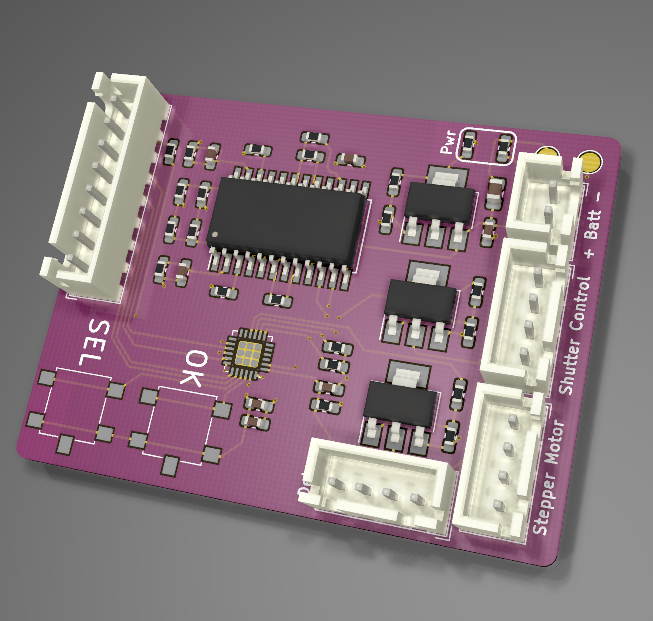
The board is a four layer stackup. Components and routing on top, 3.3V power plane, ground plane, and more routing on the bottom. The entire thing is hand-soldered, which isn't much of an accomplishment except for the 24QFN package of the MCU. Flux and drag soldering win the day!
![]()
The firmware is pretty simple. On powerup the MCU initializes the necessary peripherals and draws an opening menu to the LCD. The user can select speed (sidereal tracking or lunar tracking), timer (10 - 60 seconds on the shutter), and then start the driver. While the driver is engaged the MCU PWMs a signal to the A3967 at the rate selected by the user until the user says "Stop."
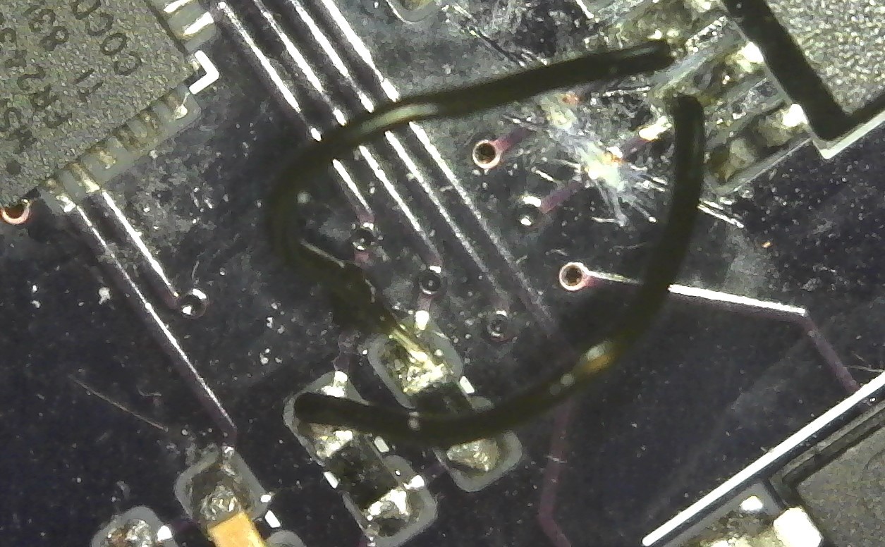
This is still a work in progress. The latest fabbed boards had a couple of traces swapped so that the MCU was PWMing the driver's DIR pin instead of STEP. Fortunately the traces were readily accessible!
![]()
The shutter control feature is also totally untested. To date I've been mostly focused (lol) on getting the basic drive mechanics going.
-
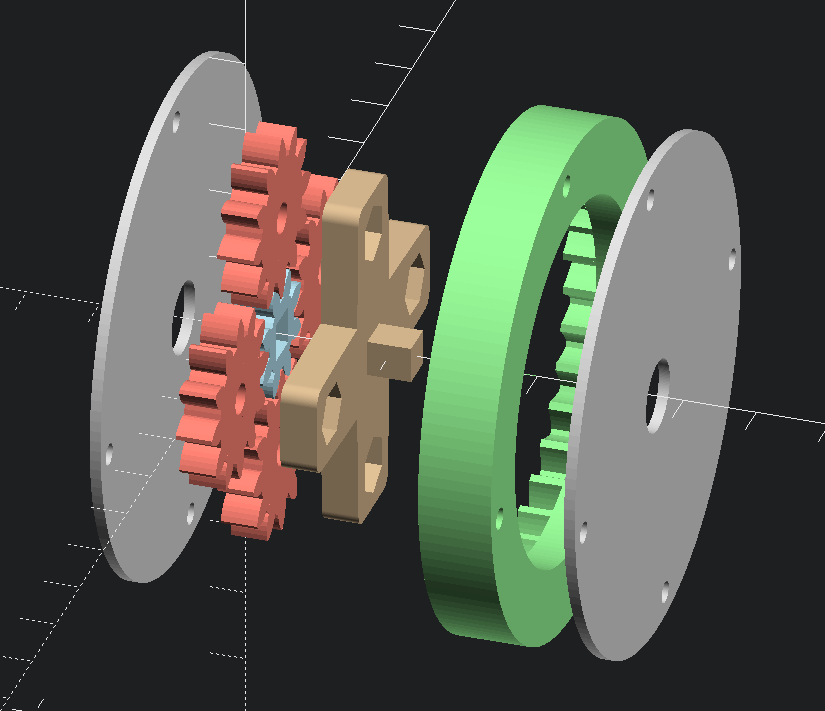
Planetary Gears
02/04/2019 at 03:54 • 0 commentsThe first iteration of this project didn't use planetary gears. Instead it used a combination of 2 : 1 and 5 : 1 straight gears on three independent shafts, plus a bevel gear to mount the stepper motor perpendicular to the axis (axes) of rotation.
![]()
It was complicated and it never worked very well. The gears were tightly constrained in the walls but without much margin for error because of the multiple axes. They had a tendency to bind and there was a lot of lash, especially in the last 5 : 1 gear which was supposed to hold the camera. Inconsistent movement and non-axial motion are not good in an application where precision timing is key.
I don't remember what made me start thinking about planetary gears but once I had the thought it stuck and so far it's working out far better. There are more moving parts - 30 moving gears plus the planetary carriers feeding each successive stage, versus only nine moving gears in the original - but all those parts are much more tightly constrained in their range of motion.
Planetary gears are harder to reason about and calculate parameters for than coaxial meshed gears. The following resources helped a lot:
- Planetary Gear Simulator - simulates a parametric set of planetary gears in your browser. To simulate a fixed-ring gear set like in this project, set the "Ring Speed" slider to zero.
- Epicyclic Gearing on Wikipedia - the equations necessary to calculate important things like gear ratio from teeth count.
![]()
-
Finding metric hardware in the U S of A
02/04/2019 at 03:01 • 0 commentsI design all my projects to metric dimensions. That's fine for straight up 3D printed parts like brackets and game board pieces but sometimes it makes finding fastening hardware difficult. The local "small" hardware stores - Ace and True Value - all have pretty much identical selection for metric screws and nuts. The big box stores - Lowes, Home Depot, and Menards - are no different, and you can forget finding screws in any "esoteric" (read: small or very long) sizes.
Talking with some folks at work I discovered that you can order from Grainger and pick up at their physical locations. Less than $20 later and I had a meter of M3 threaded rod, enough M3 lock nuts to effectively never run out, and more than twice as many 6mm M4 hex head screws than I needed. Hooray for Grainger!
Astrophotography Camera Mount
A 3D-printed 10000 : 1 gear reducer and control hardware used for astrophotography