Paul Gould
-
Mini Servo Tail
06/07/2019 at 14:38 • 0 comments -
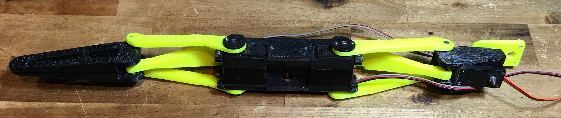
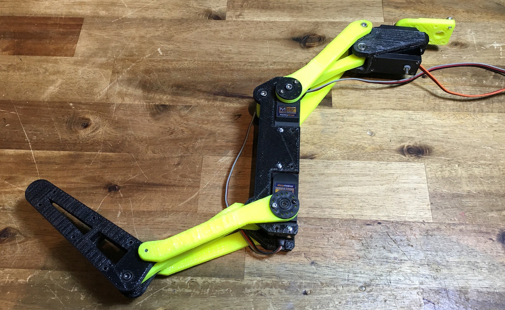
Servo Tail
06/07/2019 at 14:13 • 0 commentshttps://www.thingiverse.com/thing:3676891
3 Servos HK47360TM (23kg/cm, 0.12sec/60deg, "Titanium" Gear, 61g, HV)
Tail Rotation (left / right)
Upper Tail Curl (Double Joint)
Lower Tail Curl (Double Joint)
![]()
![]()
![]()
![]()
-
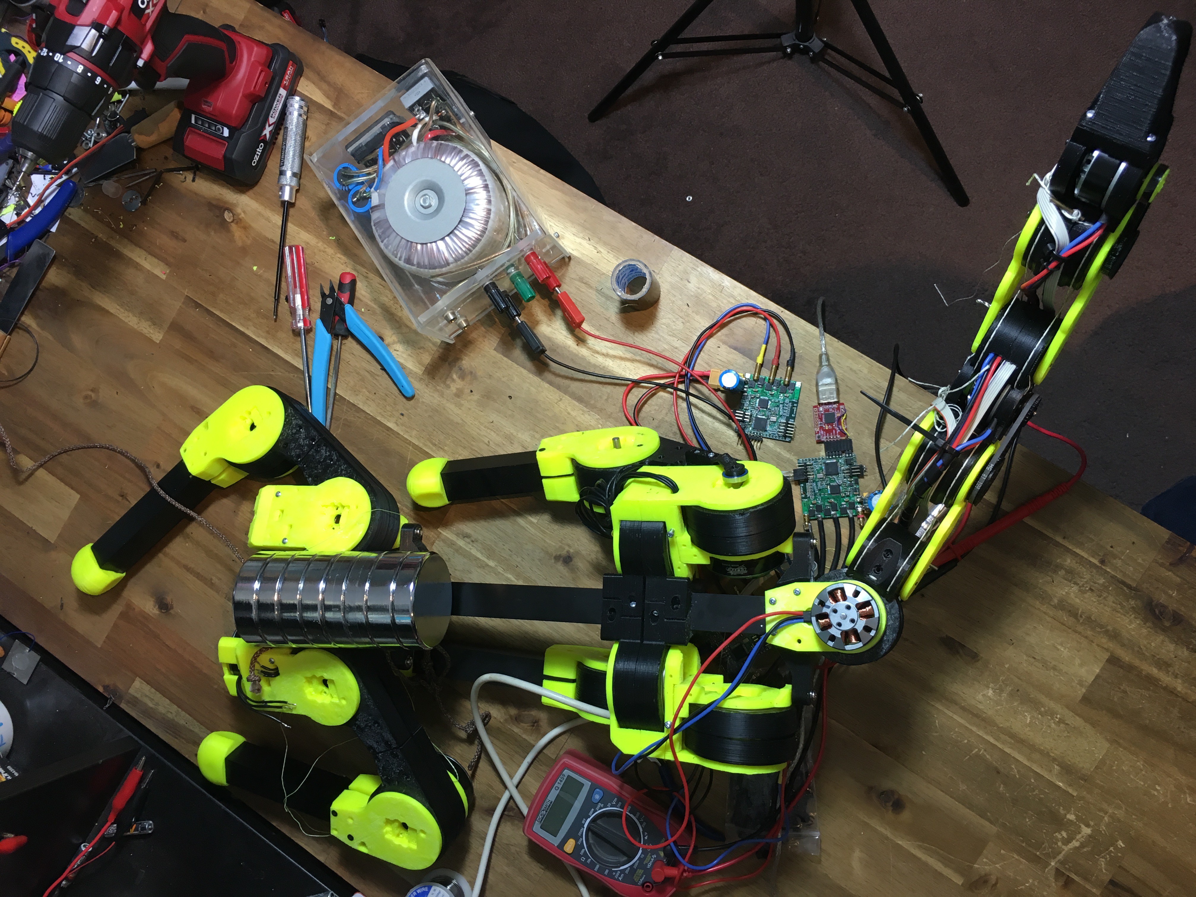
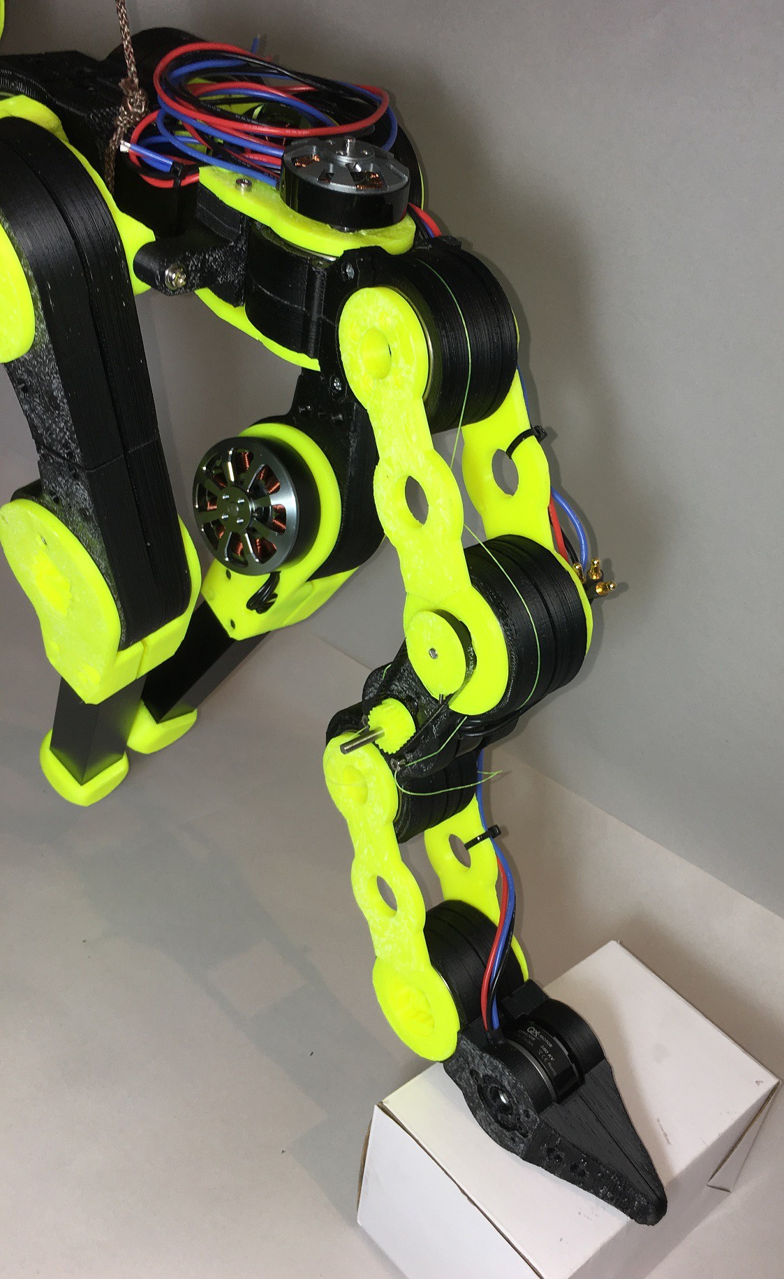
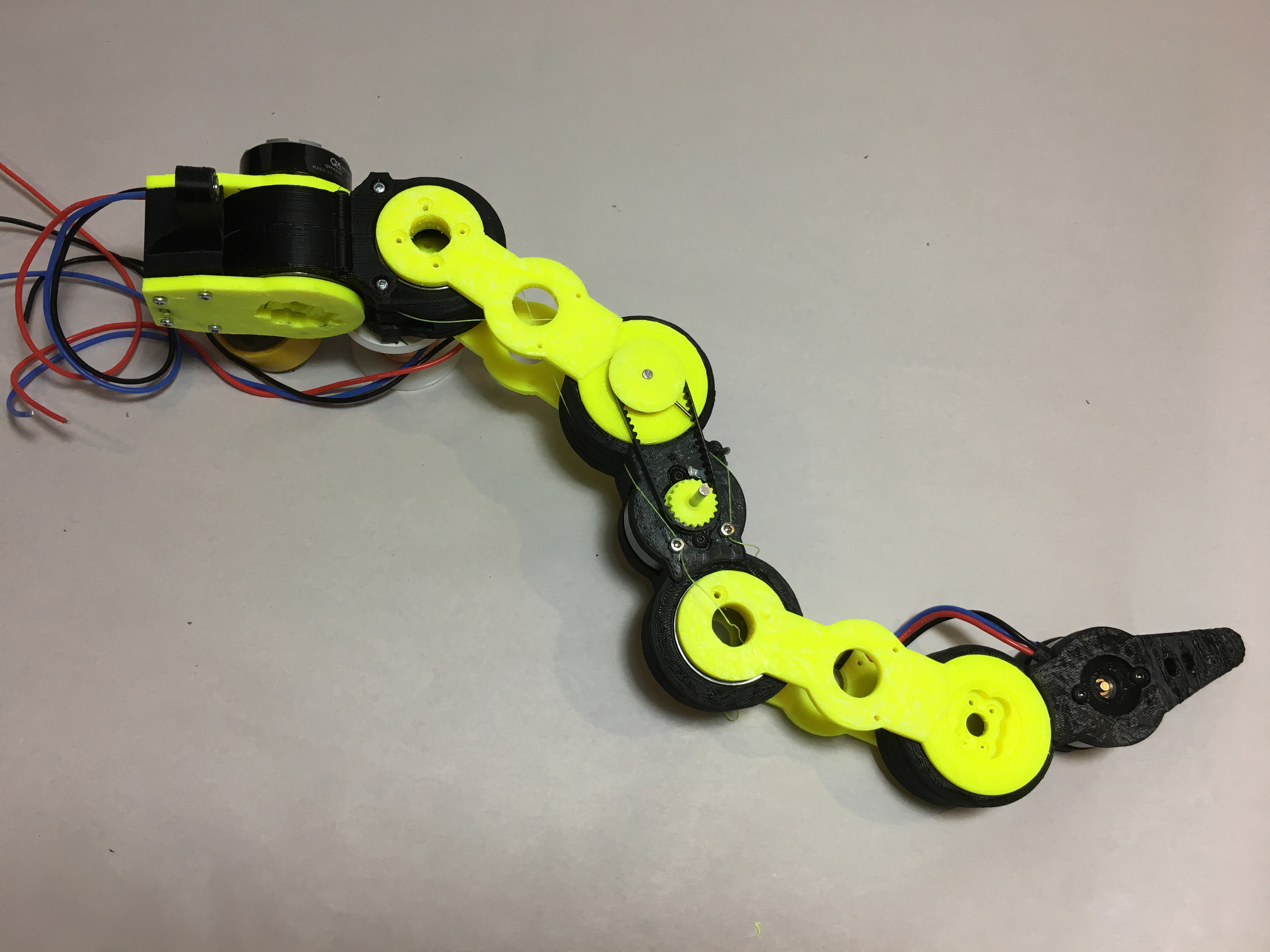
Wired up, motors calibrated, joints can move
05/06/2019 at 15:34 • 3 commentsThree motors
Three Controllers
Three Magnetic Absolute Encoders
Five Joints
1Kg
![]()
Motion Control is next
-
Testing
02/17/2019 at 16:58 • 0 commentsIt is not moving under its own power yet.
-
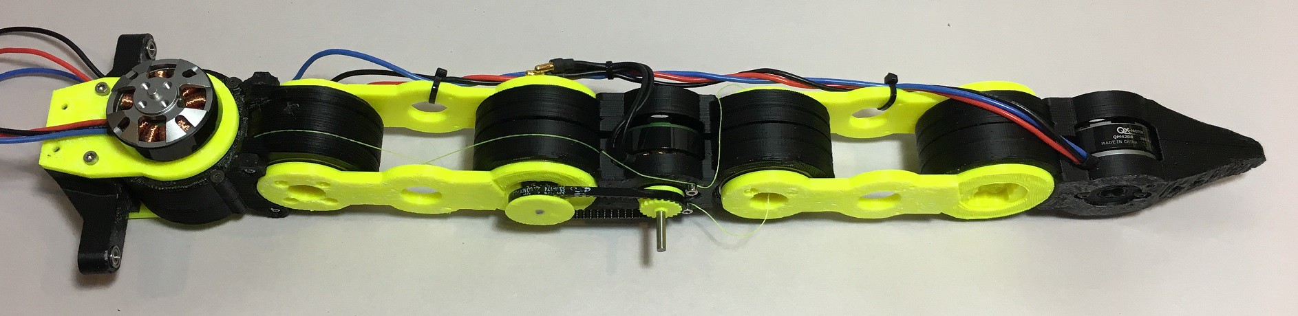
Range of motion
02/17/2019 at 16:56 • 0 commentsAll joints can move ±90°
![]()
![]()
-
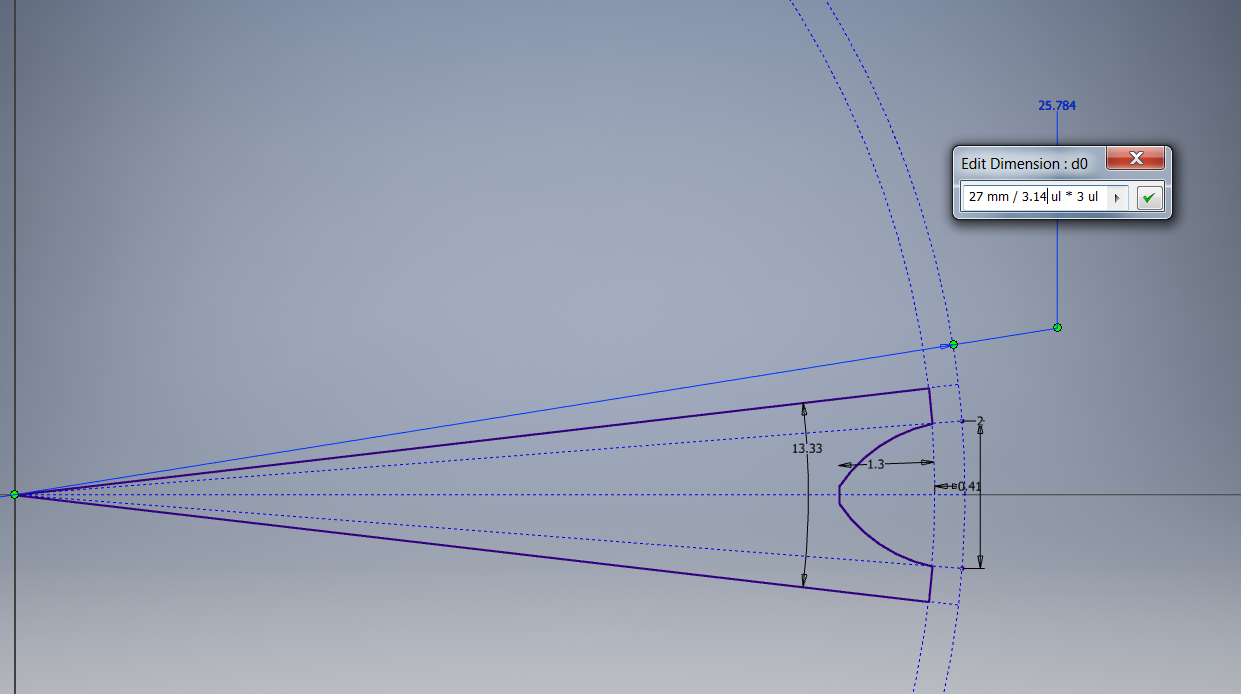
Timing Pulley
02/17/2019 at 16:46 • 0 comments3mm Pitch timing belt 27 teeth. Dimensions are from a standard timing pulley datasheet.
1.5mm Hole is for a steel pin to lock the pulley on to the shaft
![]()
-
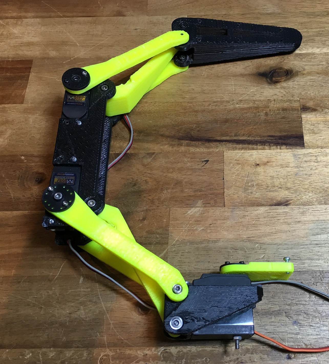
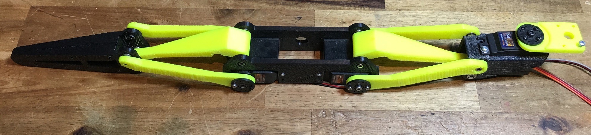
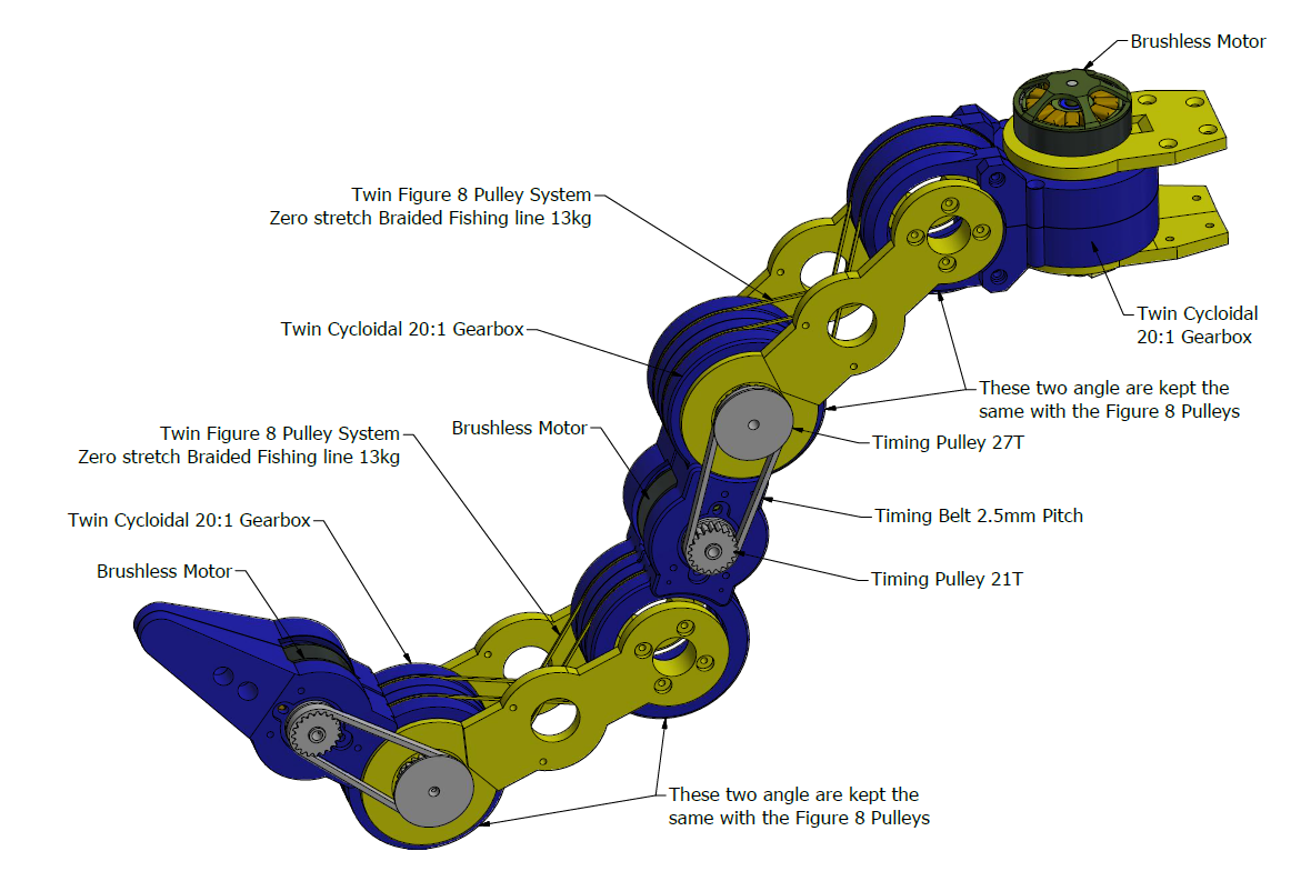
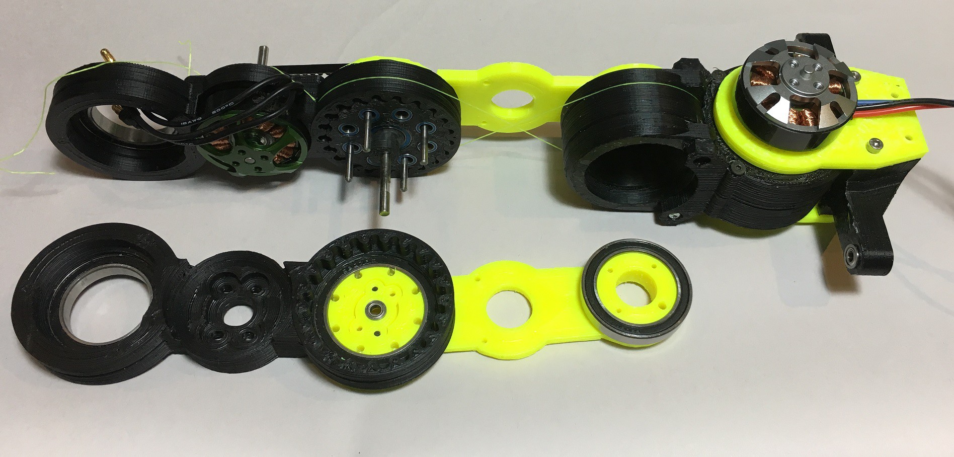
Tail Design - 5 Joints, 3 Actuators
02/17/2019 at 05:42 • 0 commentsBy linking two joints a smoother range of motion is possible with less actuators. A figure 8 pulley system using braided fishing line matches the angles of two adjacent joints.
The next step was to make the tail narrower, which meant placing the motor to the side of the cycloidal gearbox and using a timing pulley to transfer the torque. The joint can now be made 55mm wide.
![]()
![]()
![]()
![]()
-
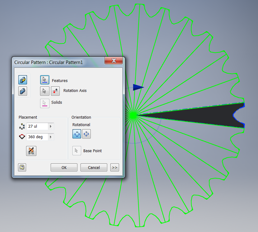
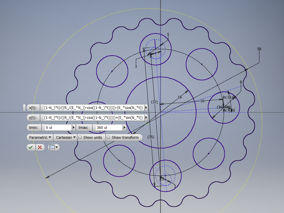
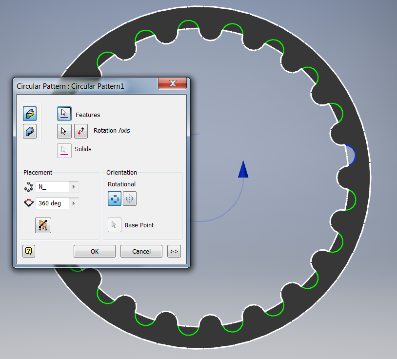
Gear box Design
02/17/2019 at 05:09 • 0 commentsBackground
Autodesk Inventor Parametric Design Cycloidal Gear (from my other project)
N_ (number of rollers)= 21 ul
number of teeth = number of rollers - 1
E_ (eccentricity) = 1 mm
Rr_ (radius of rollers) = 2 mm
R_ (radius of Rotor) = 25 mm
x(t) = (R_*cos(t))-(Rr_*cos(t+atan(sin((1-N_)*t)/((R_/E_*N_)-cos((1-N_)*t)))))-(E_*cos(N_*t))
y(t) = (-R_*sin(t))+(Rr_*sin(t+atan(sin((1-N_)*t)/((R_/E_*N_)-cos((1-N_)*t)))))+(E_*sin(N_*t))
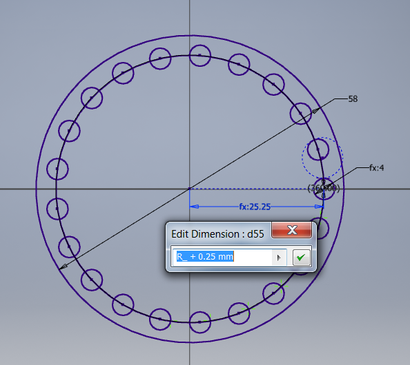
Outer ring design (replaces rollers)
The + 0.25mm is the tolerance added to on my 3D printer to make it work nicely.
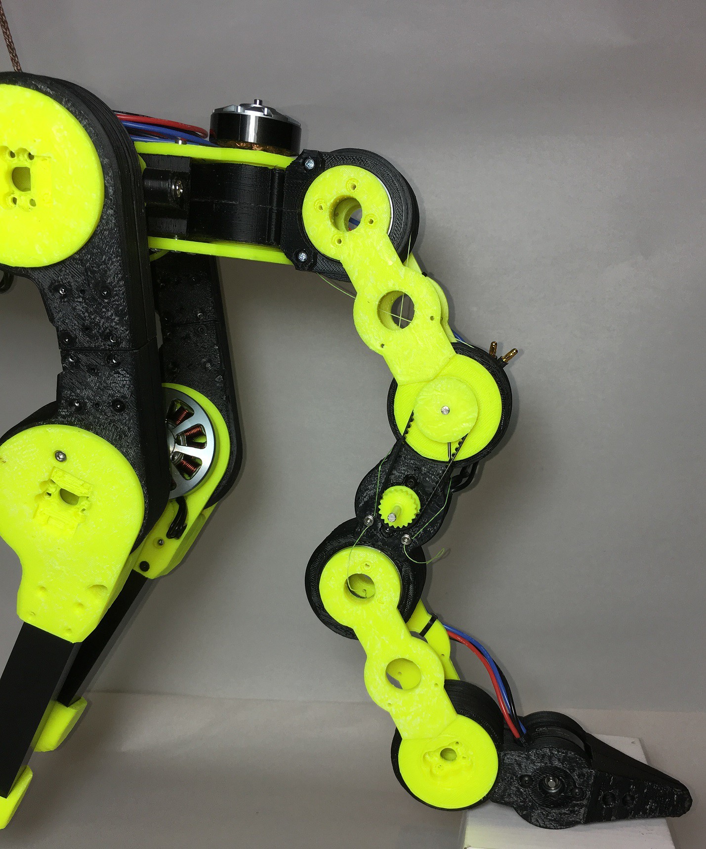
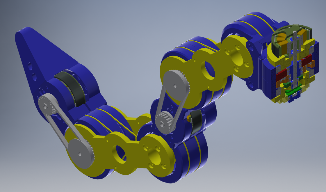
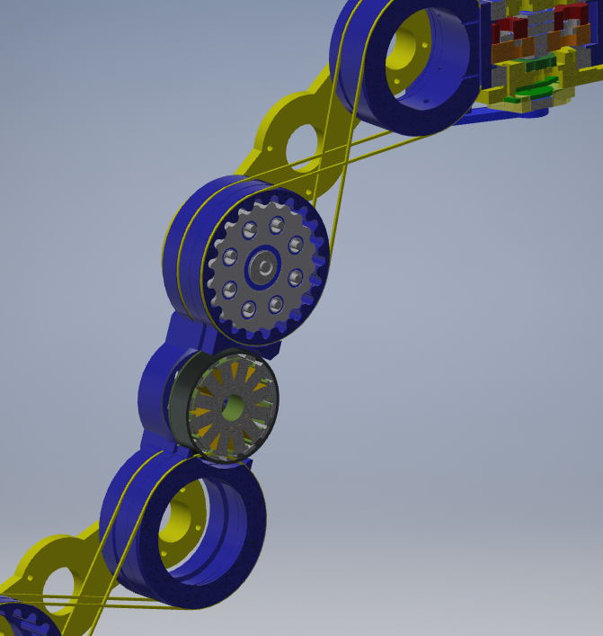
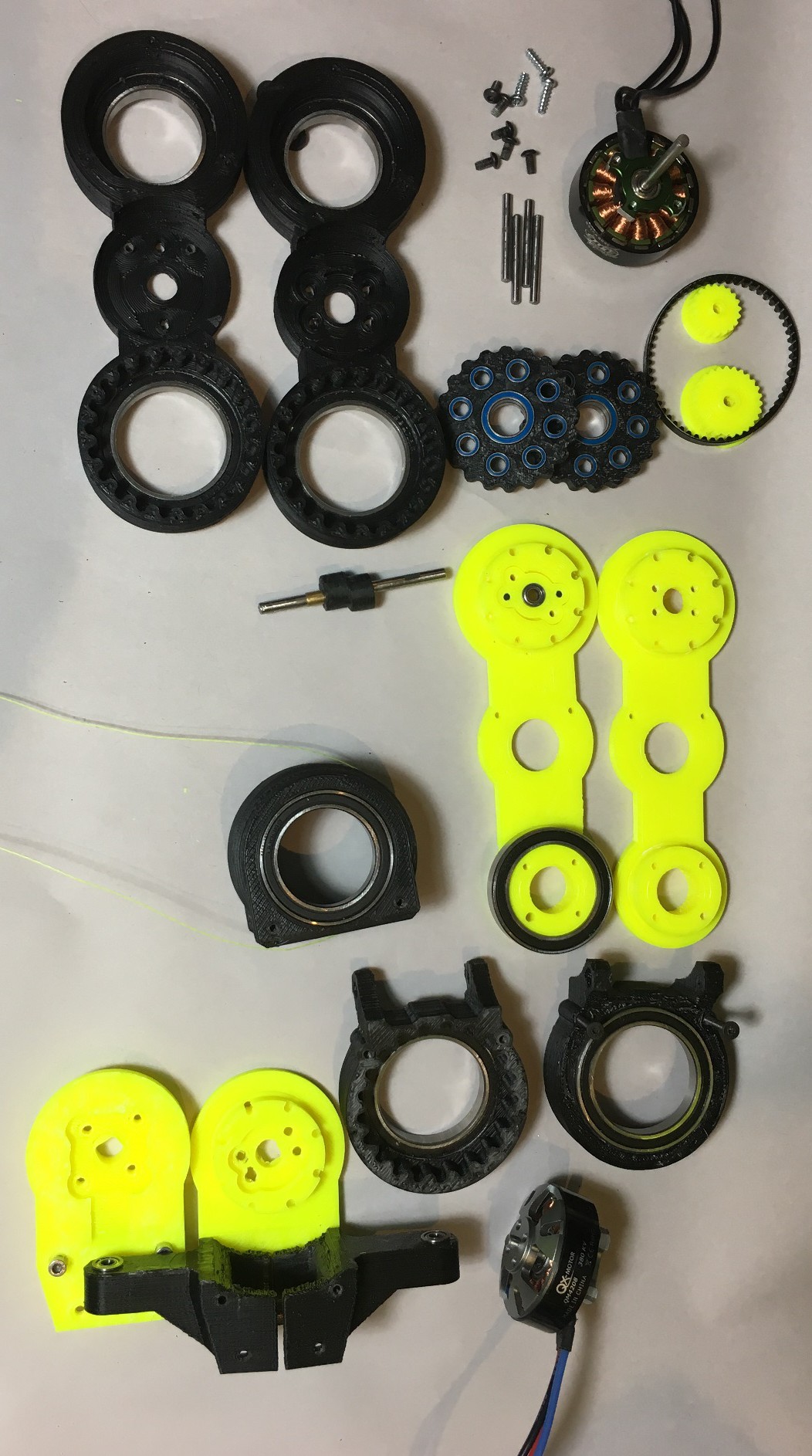
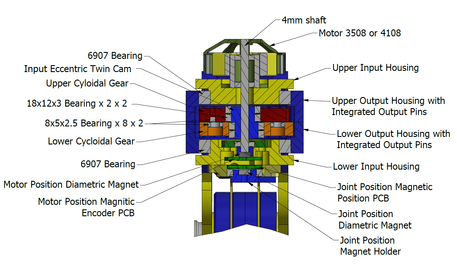
The whole actuator consists of a brushless motor, motor position sensor, cycloidal gearbox, joint position sensor. All of this is controlled by my custom BLDC controller.
Cutaway of the Upper Actuator
This actuator is a similar to the ones used by the legs. It is just a bit smaller. It is only used to "swish" the tail side to side. This type of actuator is 75mm high. This is way too wide to be used for the tail's lower joints.
-
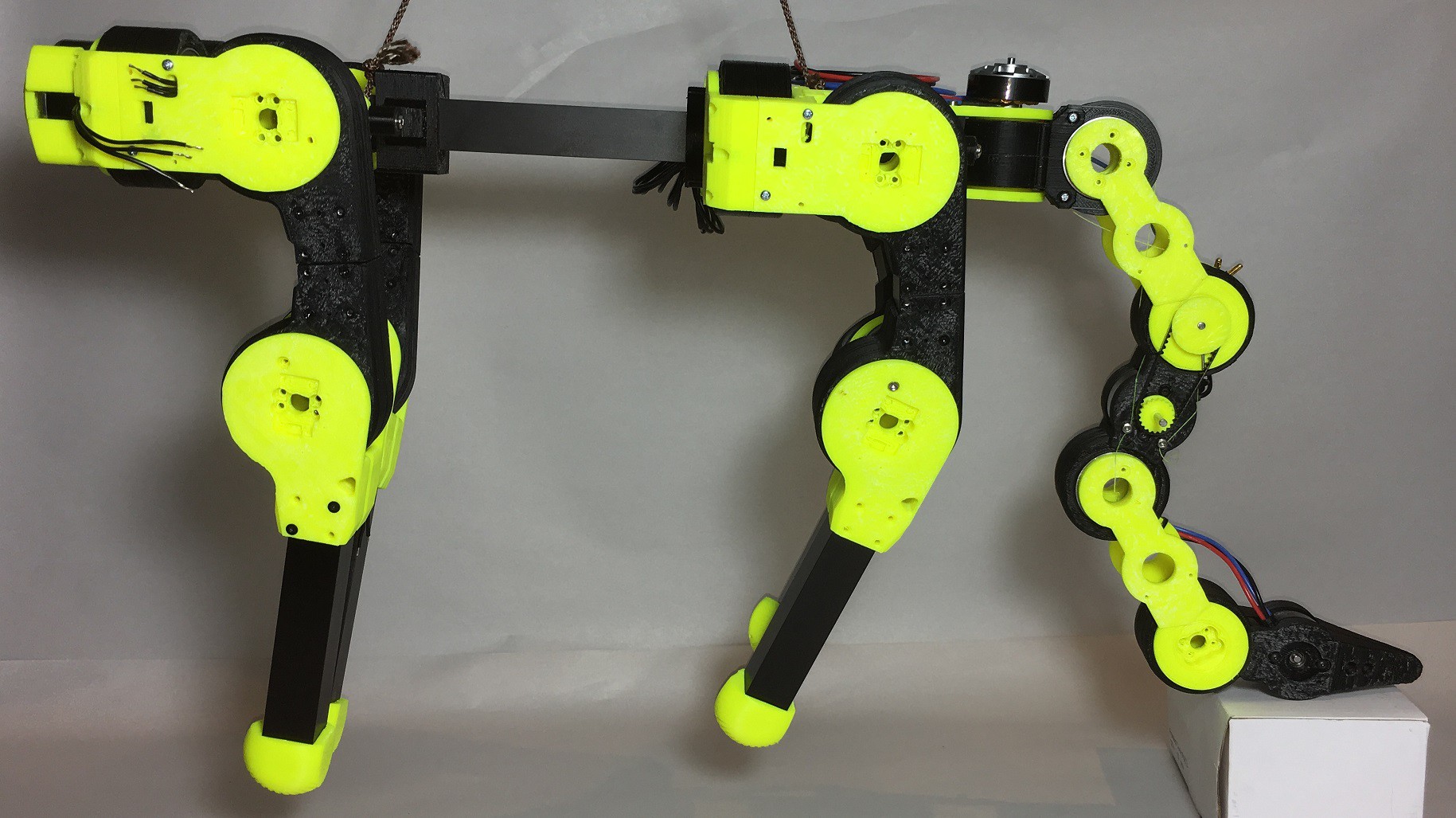
Quadruped Tail
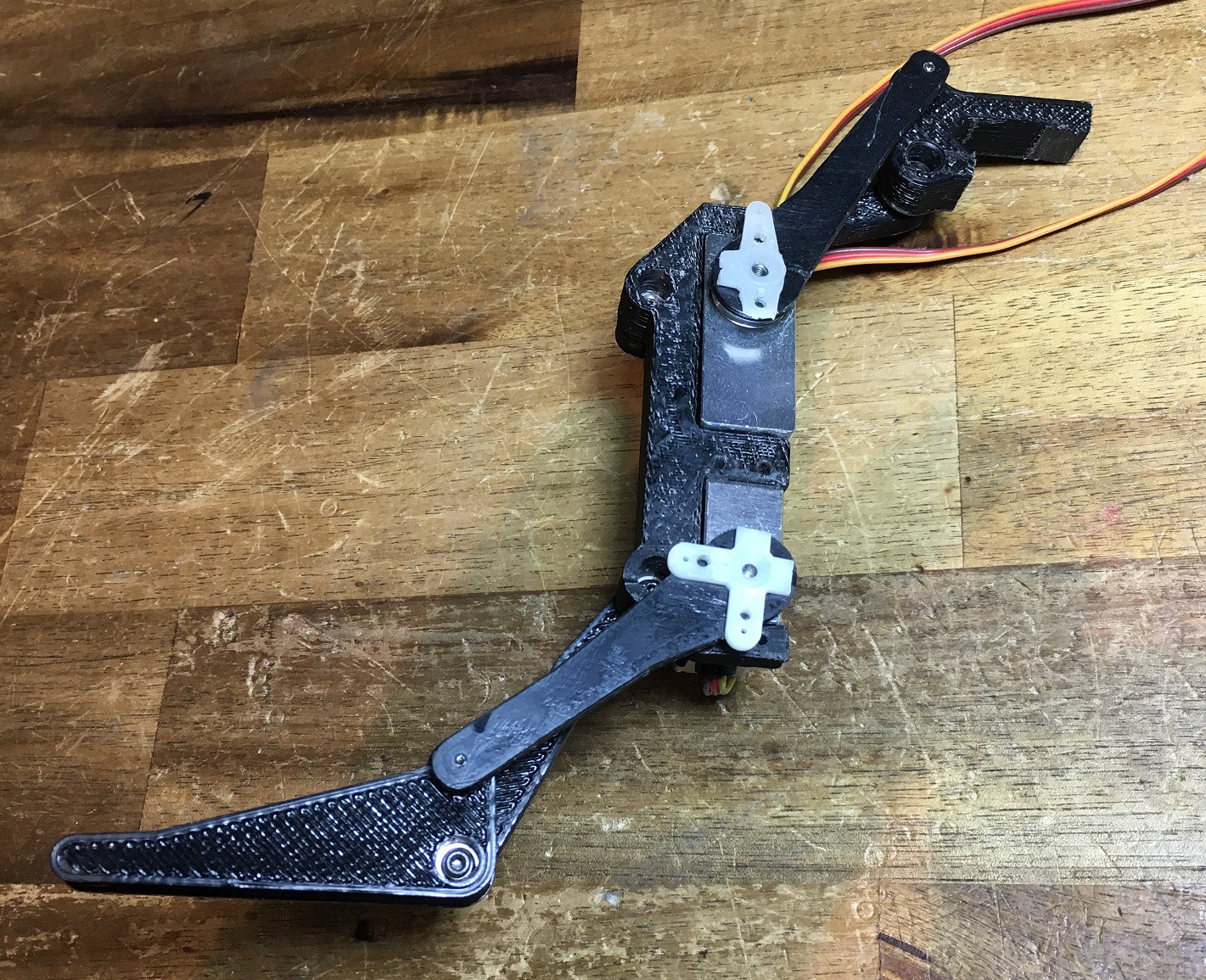
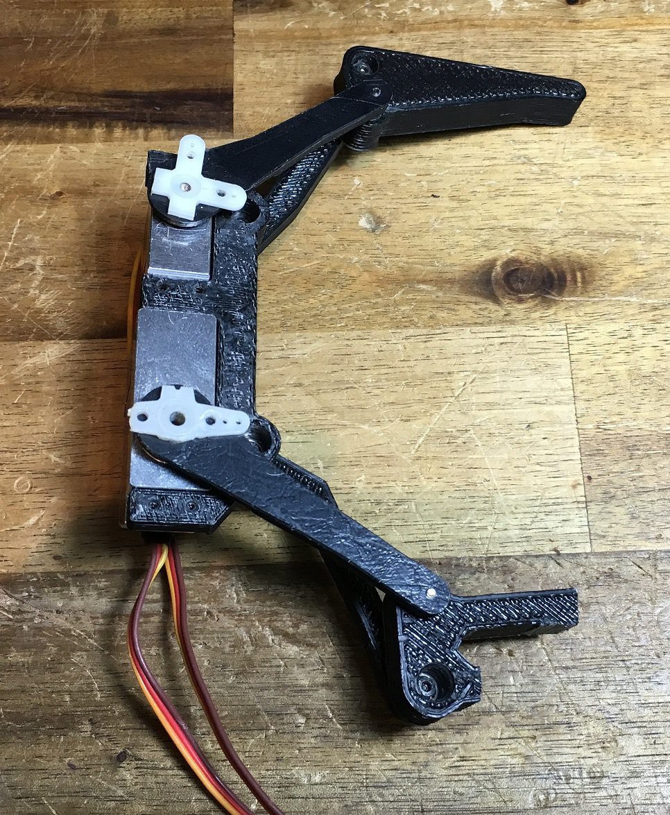
02/07/2019 at 13:37 • 0 commentsLast year I started a new, light 3D printed quadruped using cycloidal gearboxes. It now needs a tail.
![]()
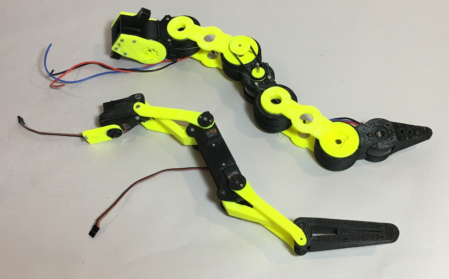
The first design was based around standard RC servos but it was a bit boring. Does there need to be a good reason??? It was a bit slow, lacked torque and had a limited range of motion. Servos were HK47360TM.
![]()
My 3D printer is an very cheap i3 clone. It has an enclosure and a ported extraction system. I print only in cheap ABS, with a raft, on a perforated board. So removing the prints from the bed takes a long time.
The tail is not finished but it seemed time to share the design in the "3D Printed Gears, Pulleys, and Cams Contest". The cycloidal gearbox has been proved in the previous project but this time the roll pins has been replaced with 3D printed parts. This reduced the number of parts by half and take ten times less to make. Bearings are still used to handle the torque. Cycloidal gearboxes are great at sharing the torque across multiple "teeth" and "rollers".
Low Cost 3D printed Robot Tail
Cycloidal gearbox, brushless motors and Timing Pulleys