 Plasmode
Here are Tiny030 design files:
Schematic, the schematic was created with the now obsolete WinDraft by IVEX. The labels in green color are connections hooked up in pc board. The labels in blue color need to be manually hook up.
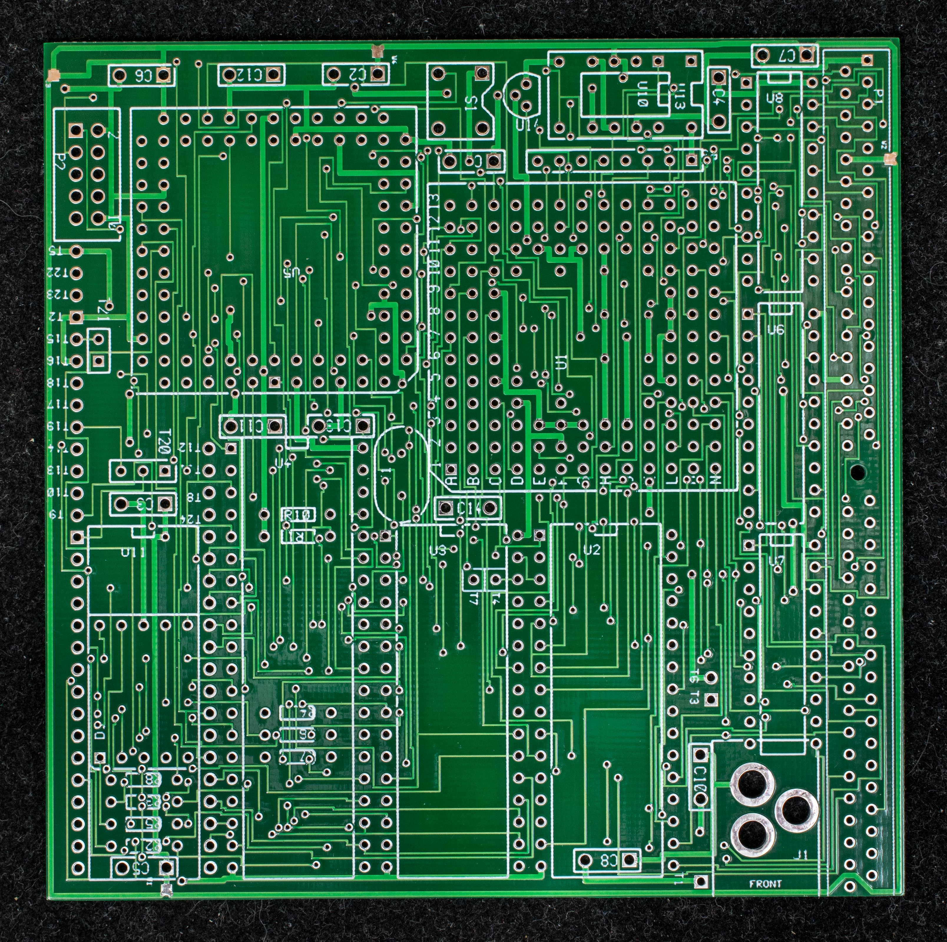
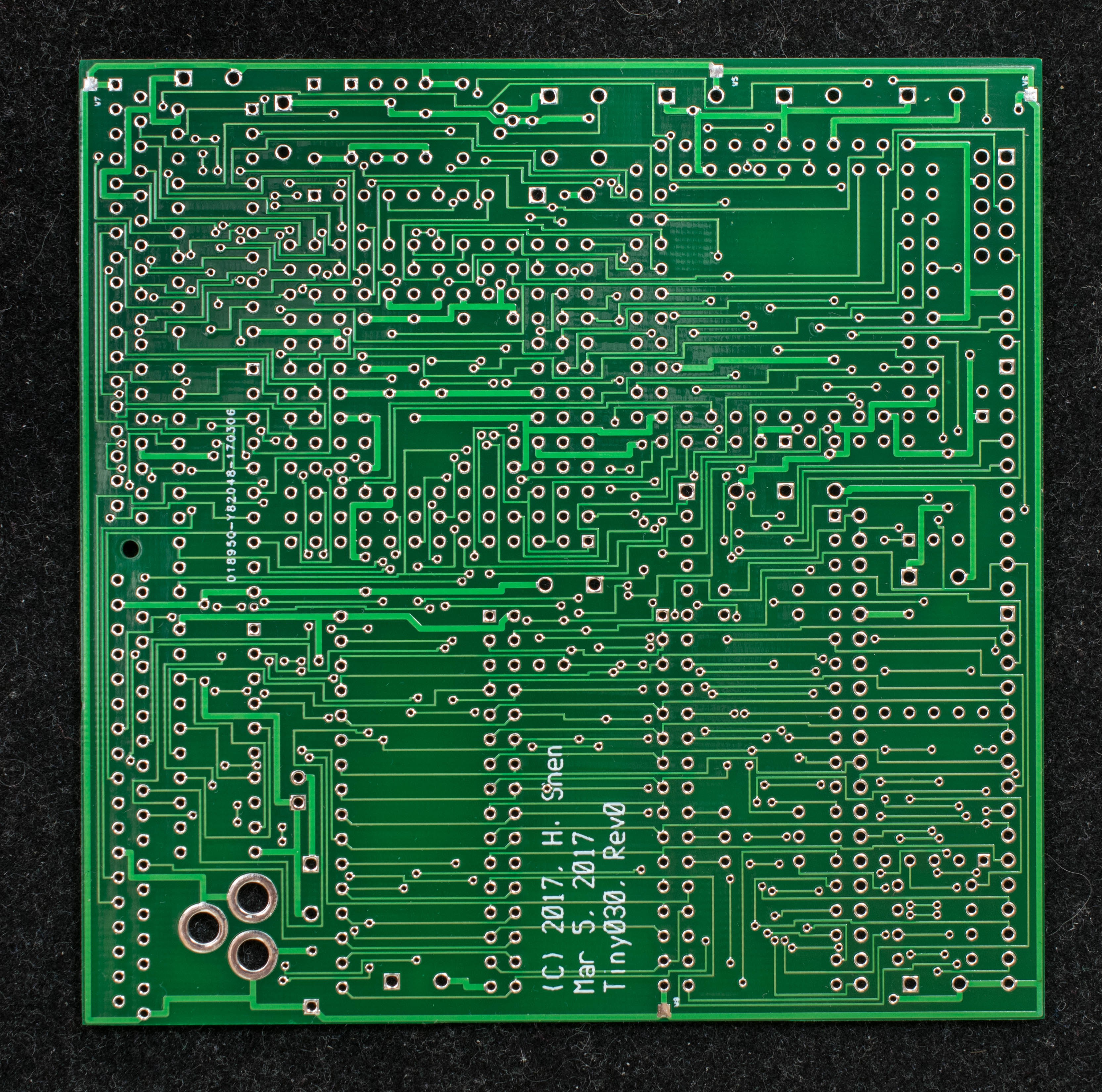
PC board gerber photoplots. This board is layout with WinBoard by IVEX. The pc board was manufactured by SeeedStudio.
The 5 stages of construction are:
1. Assemble and programming the CPLD to blink a few LED,
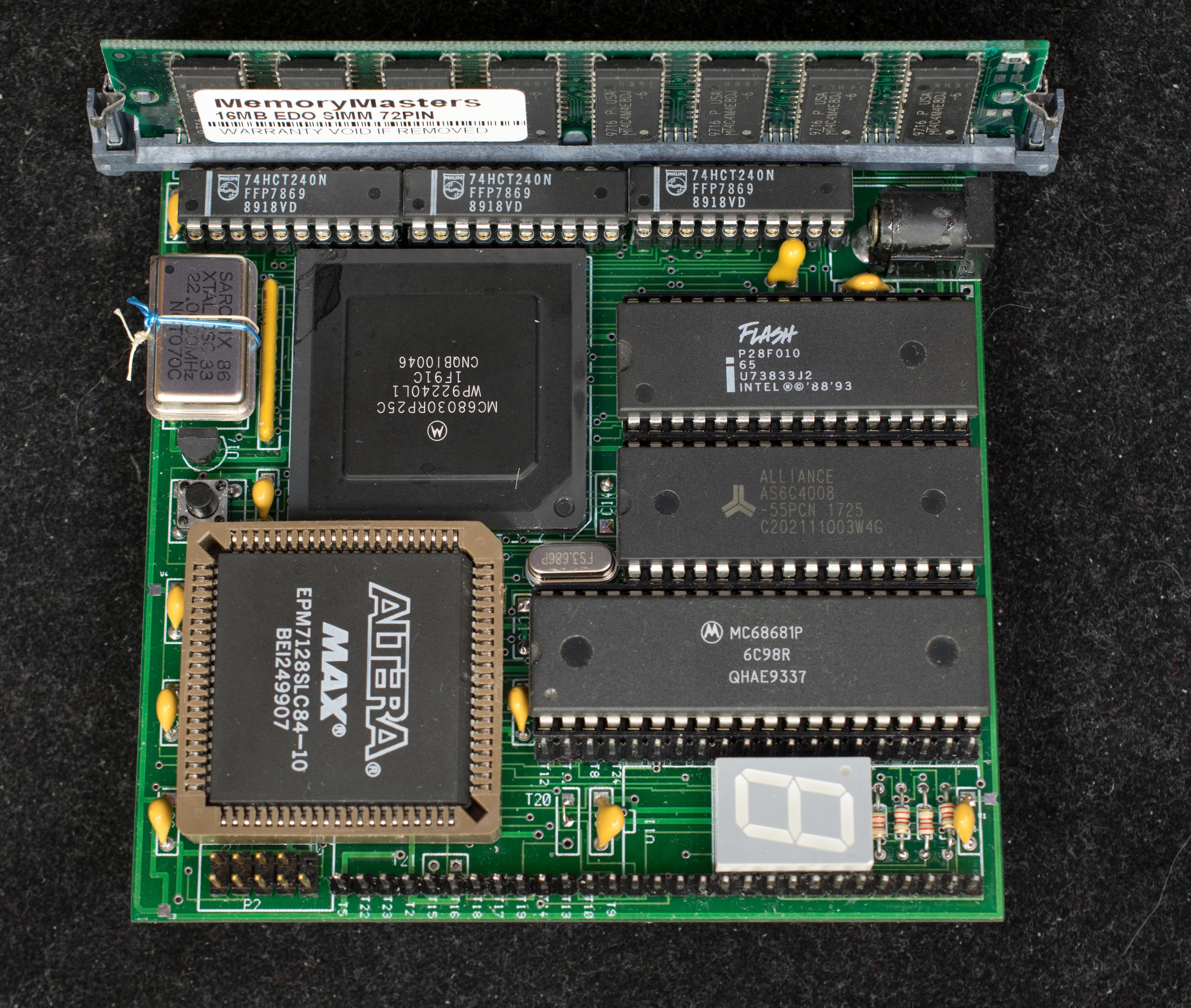
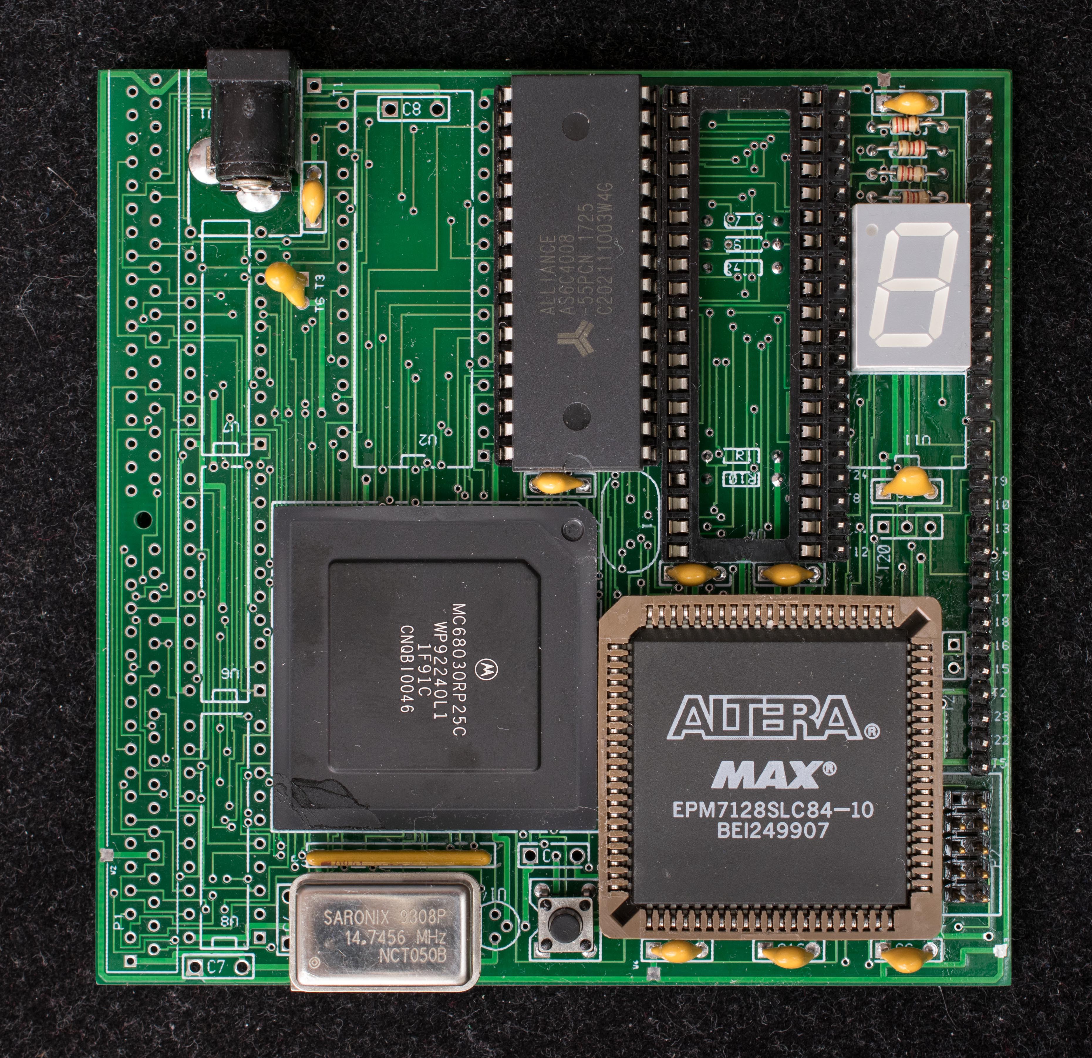
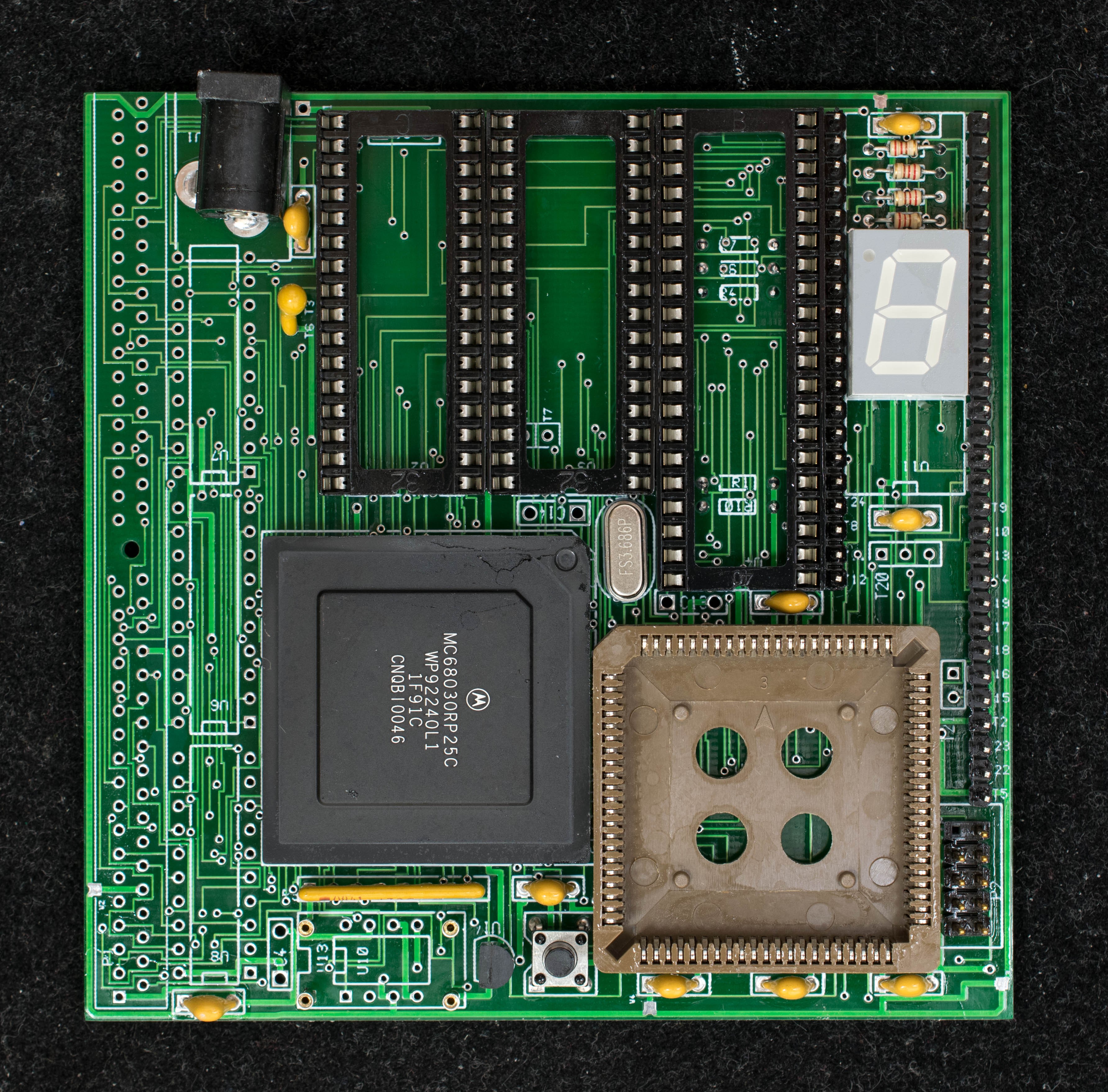
- A minimum functioning 68030 with 3 chips,
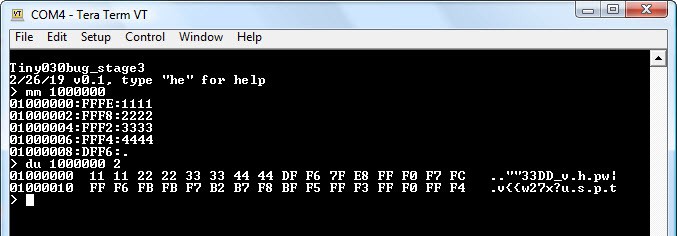
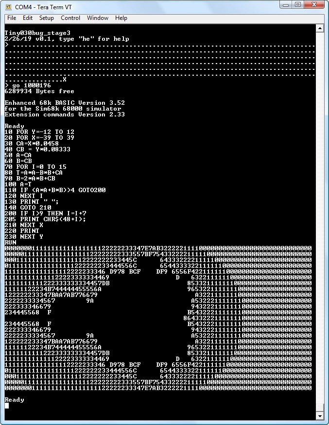
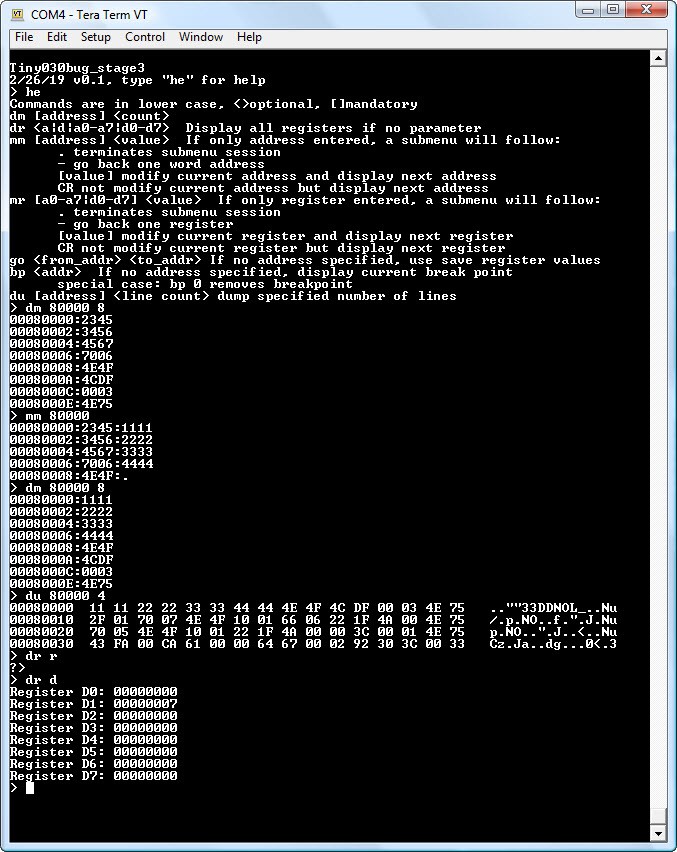
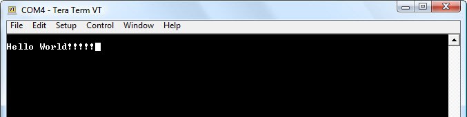
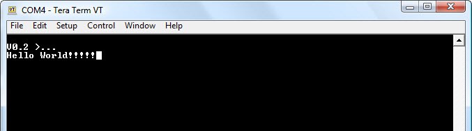
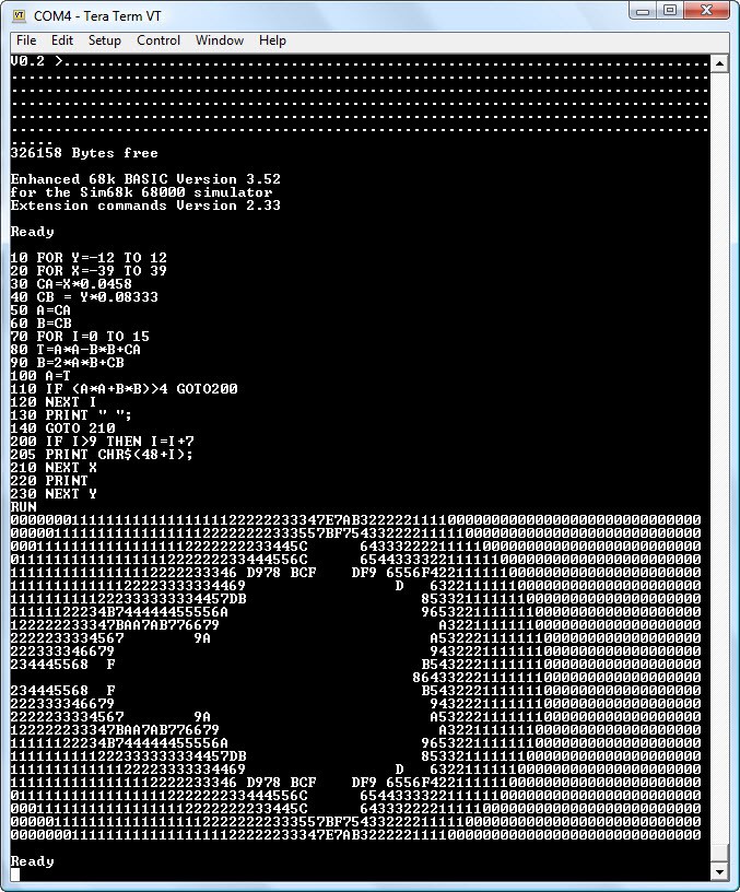
- Running software on the minimum 68030 computer
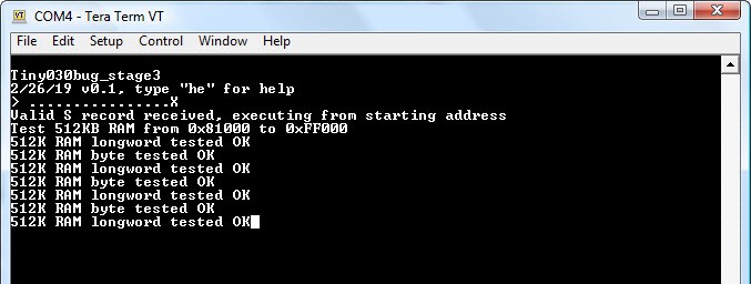
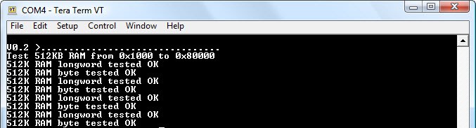
3. Basic 68030 with Serial port, RAM, and EPROM
4. 68030 with 16-meg DRAM,
- Stage 4 Hardware, Adding 16-meg DRAM
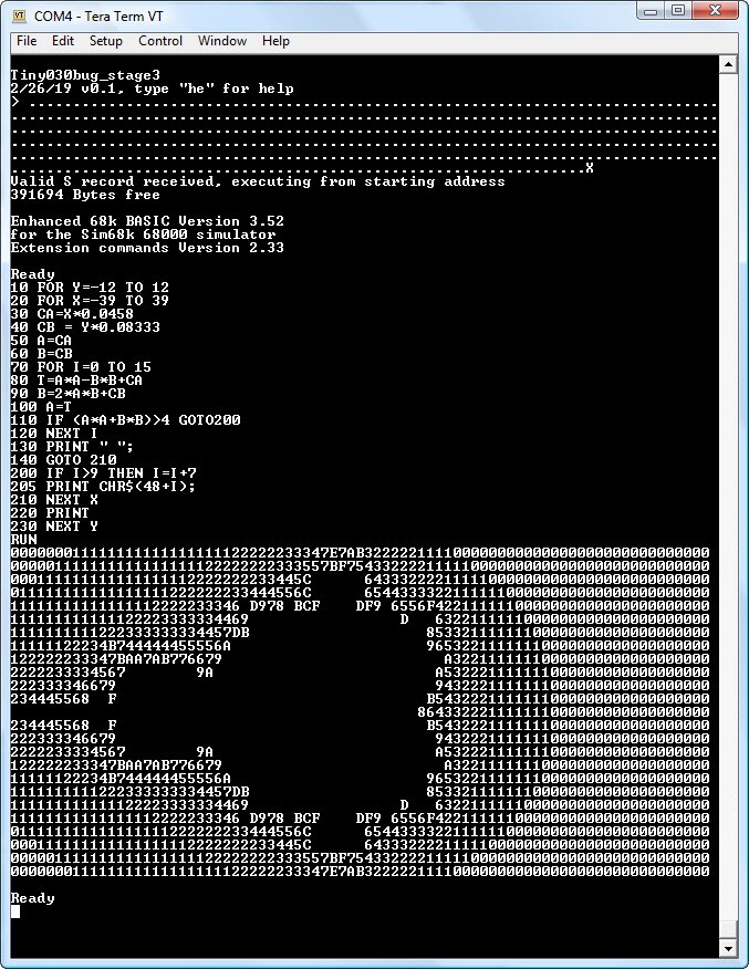
- Stage 4 Software,
5. CP/M-68K ready 68030 computer.

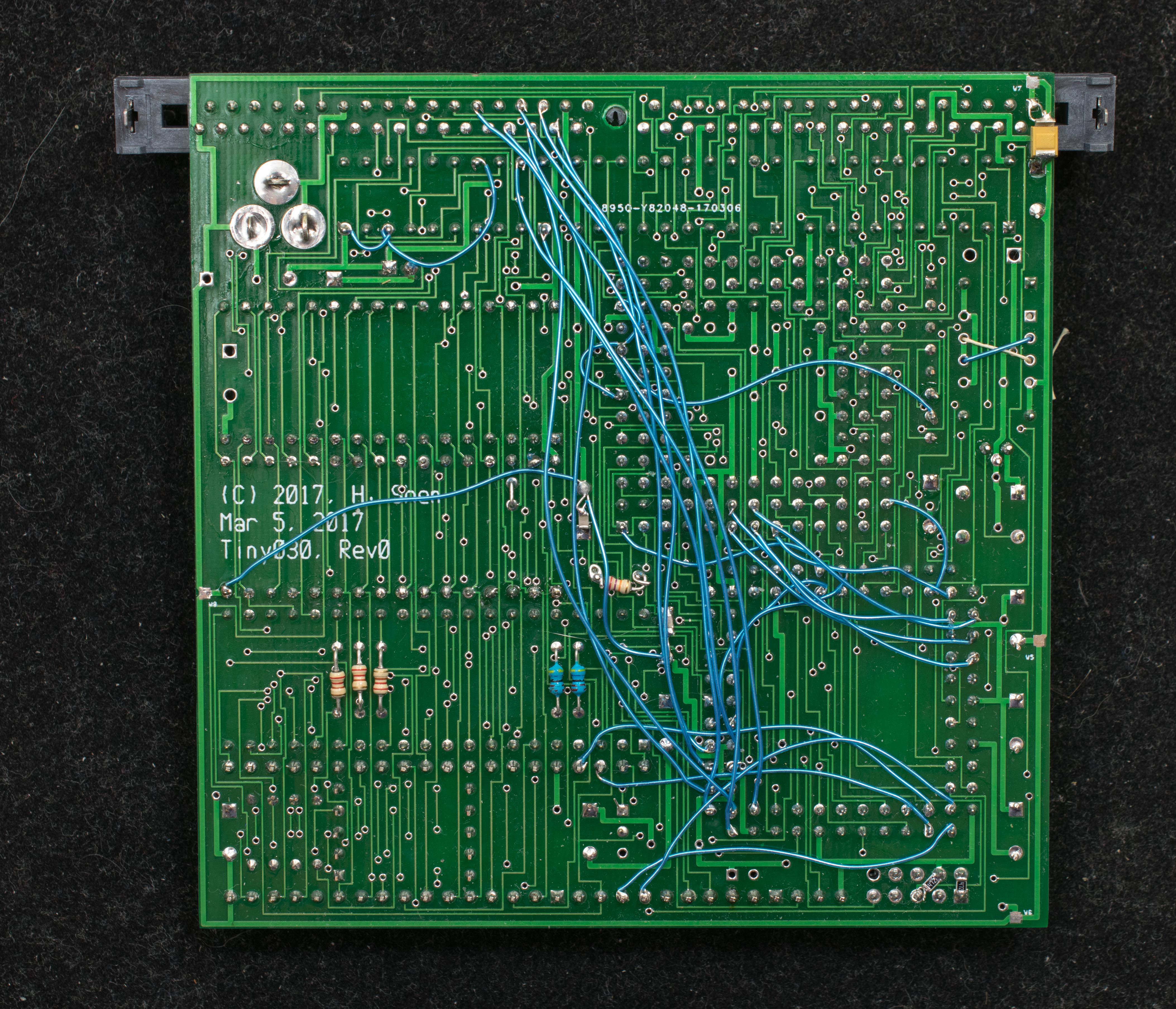
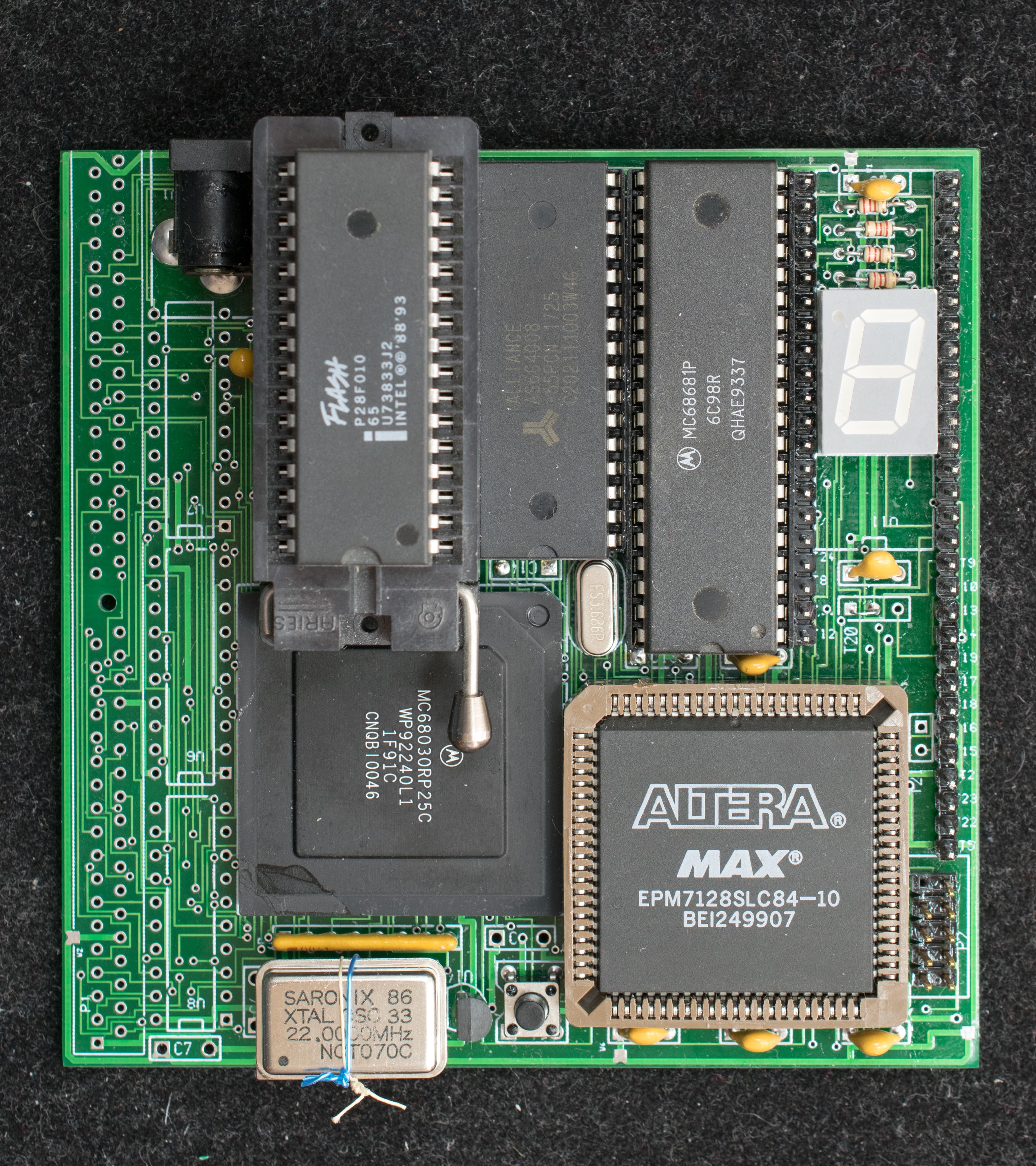
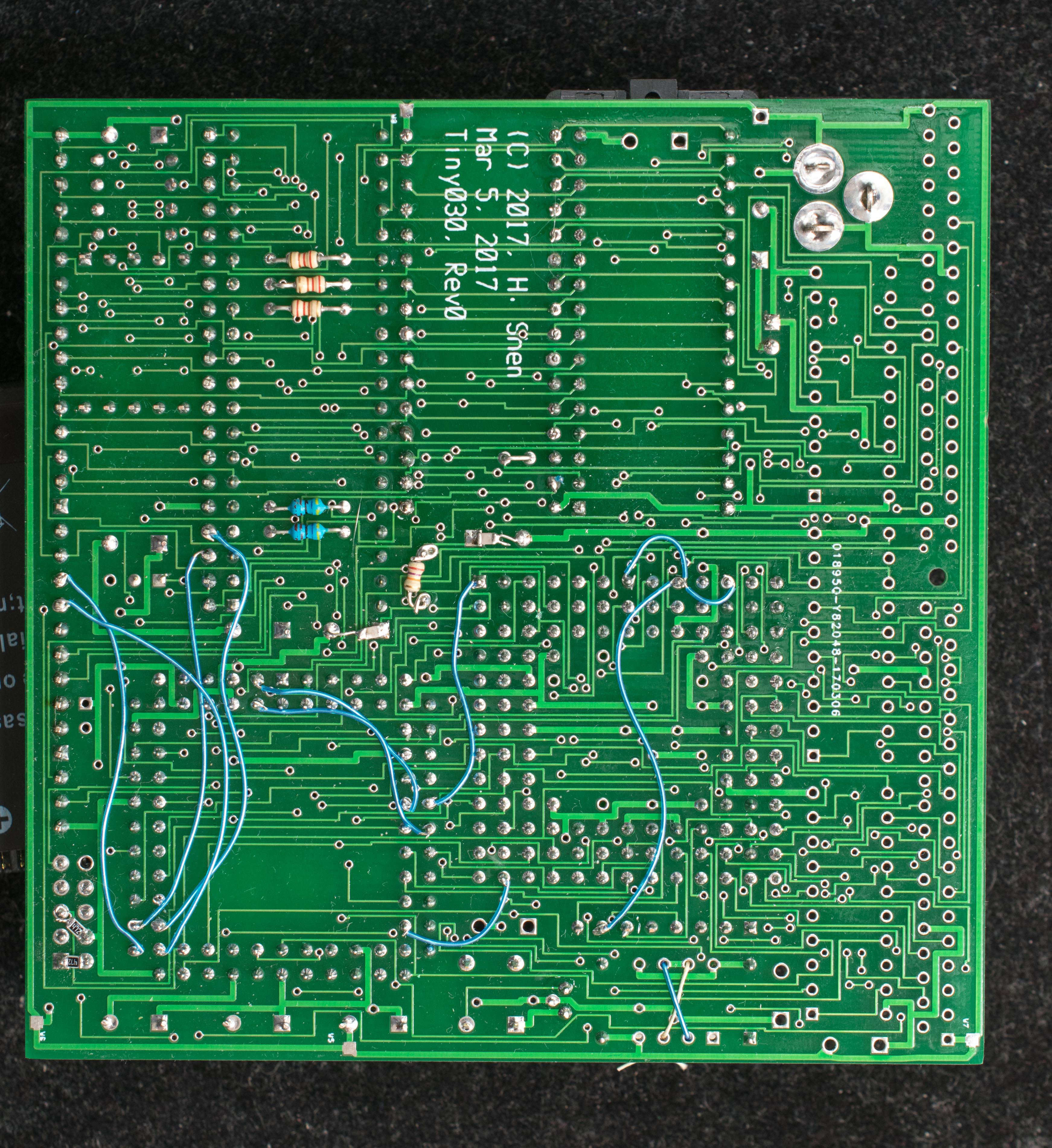
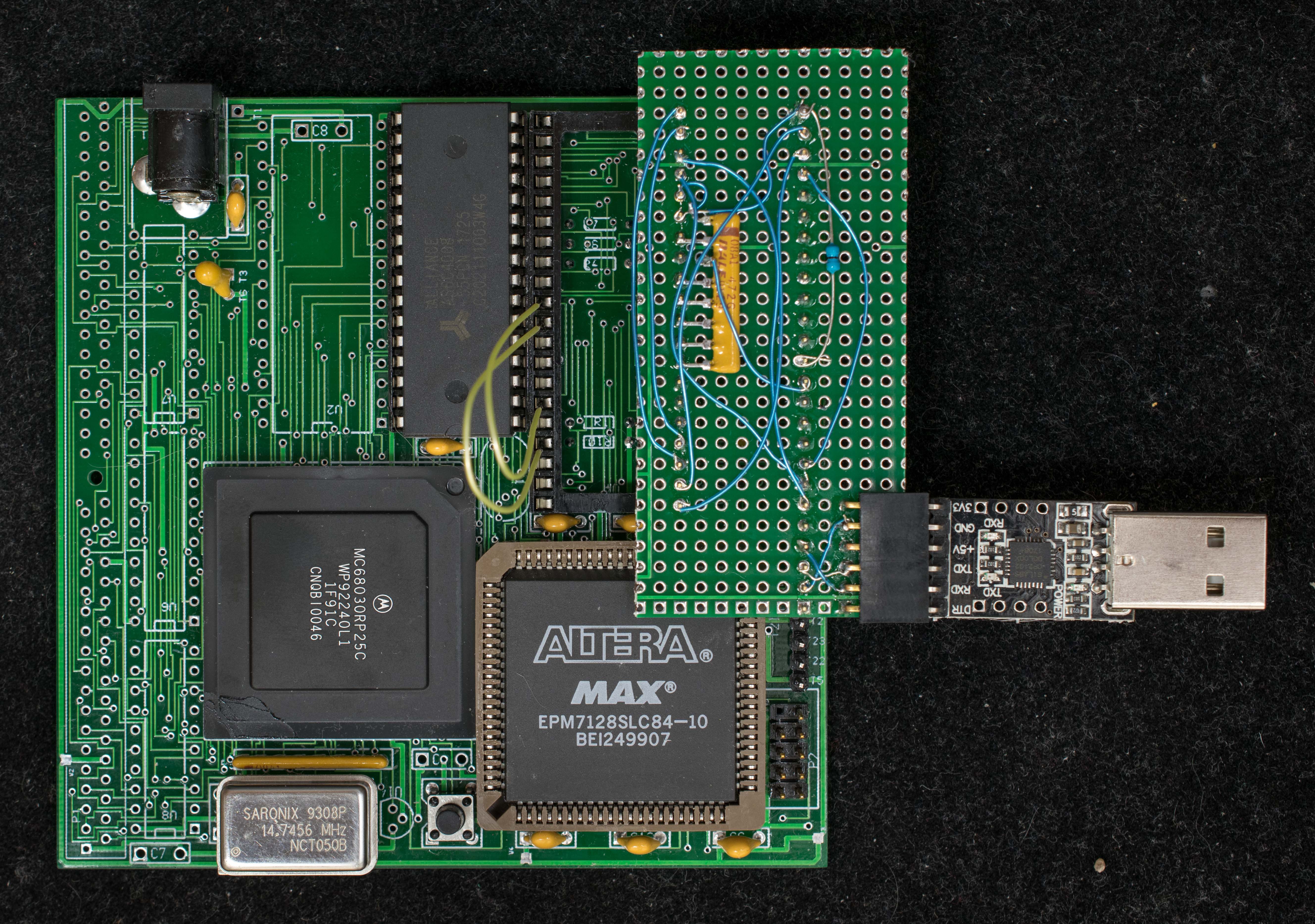
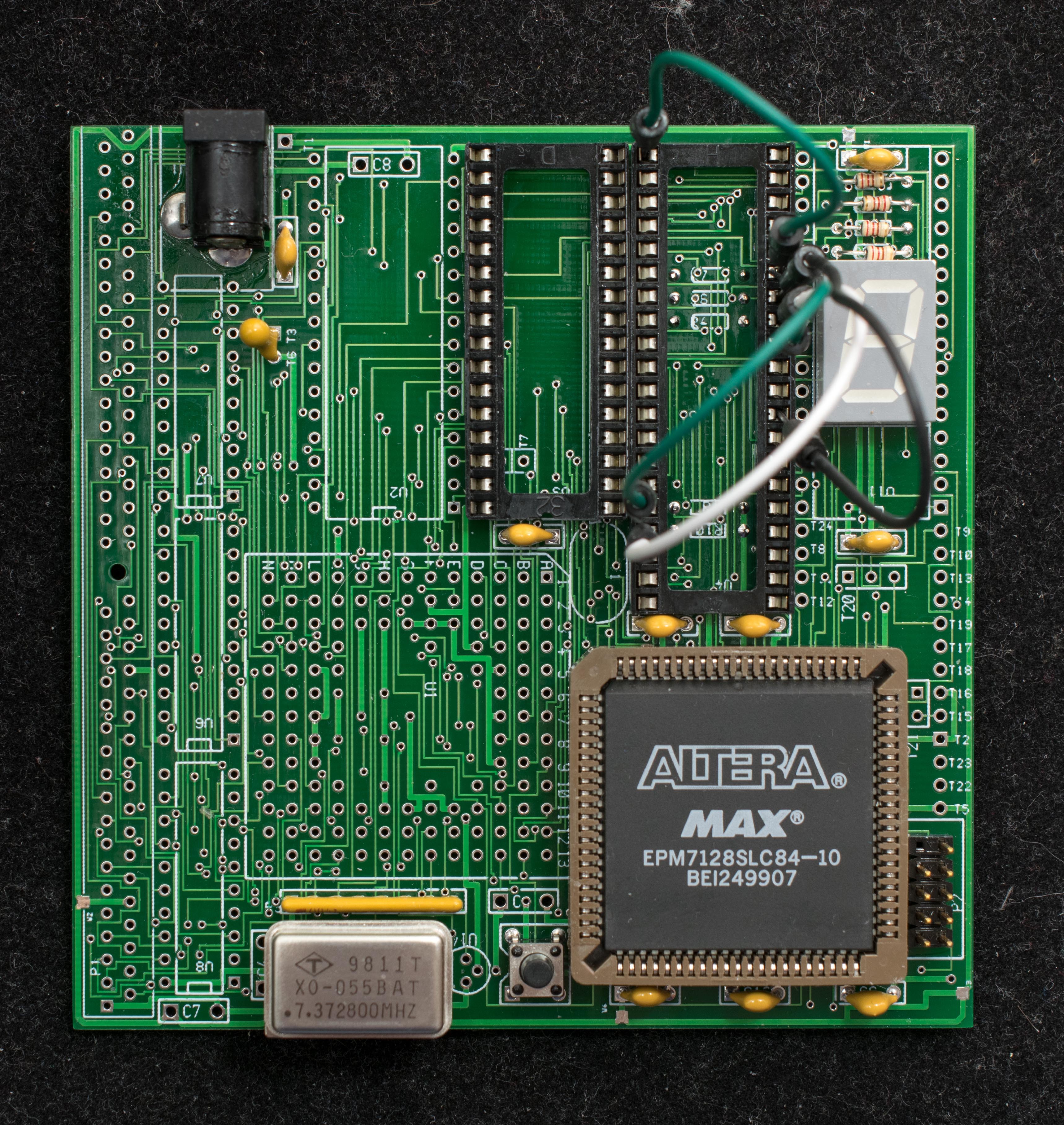
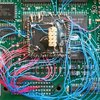
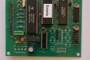
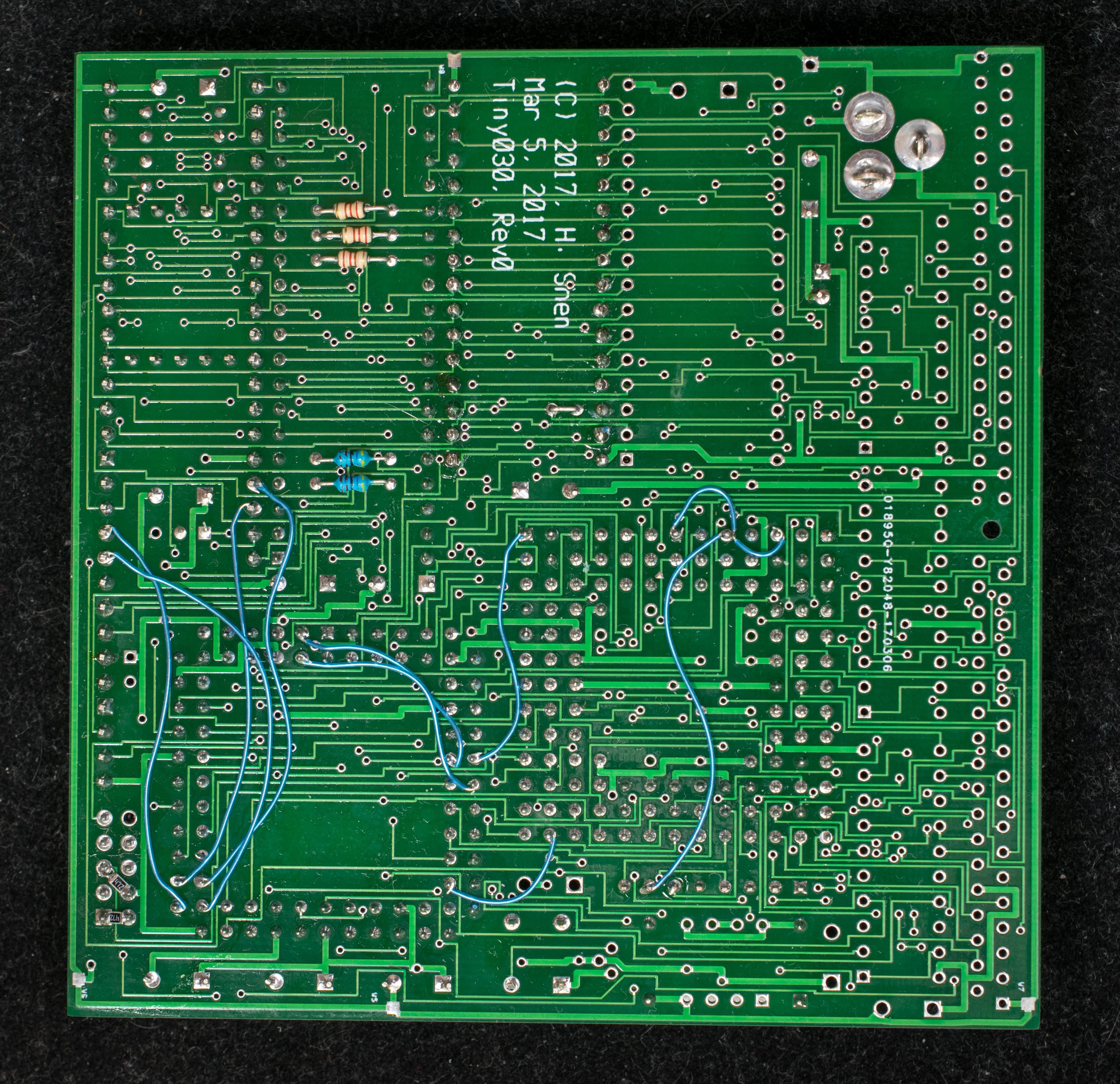 A prototype board with additional manual wires need to plug into the expansion headers, U11 to enable the serial bootstrap function
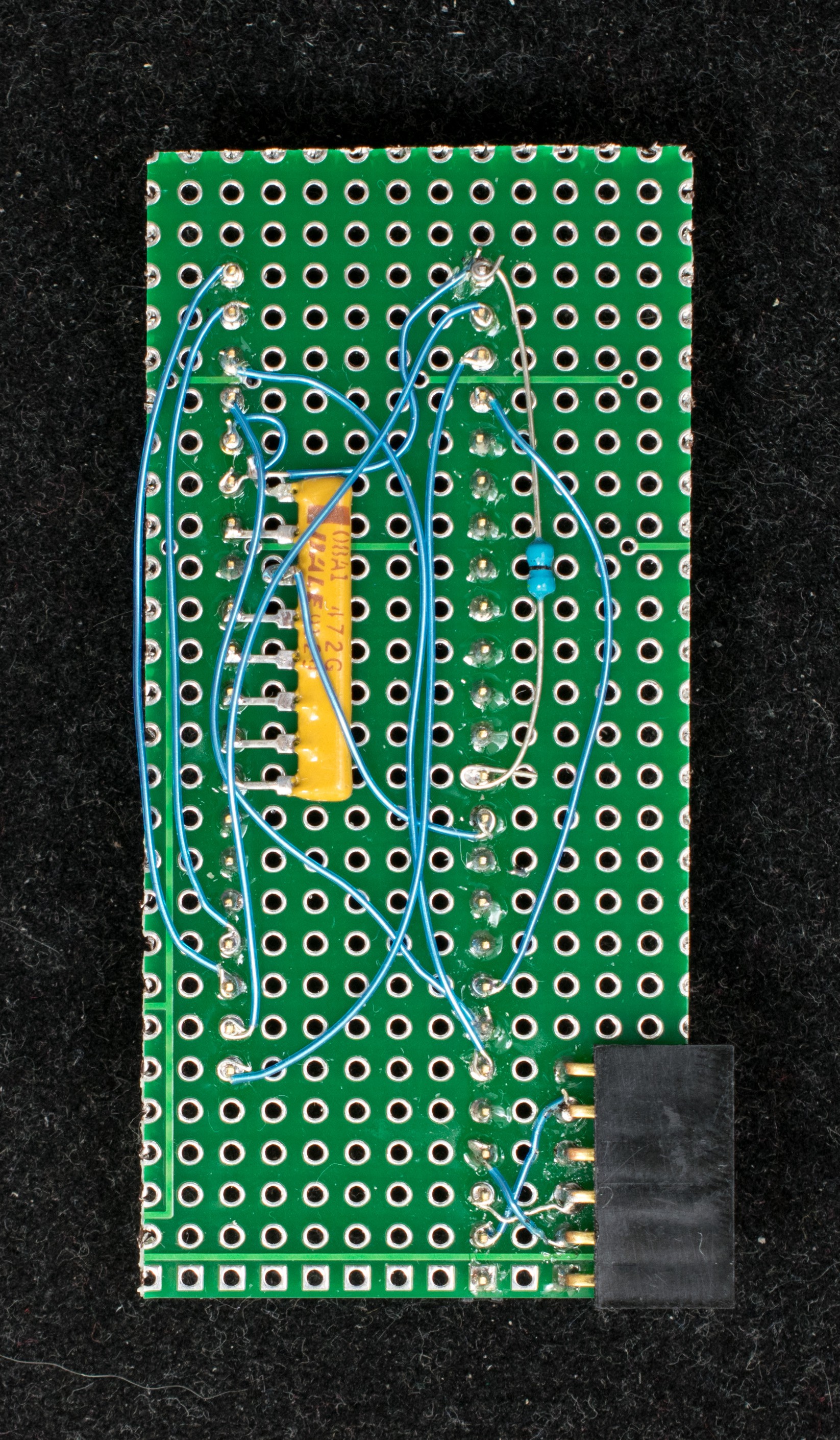
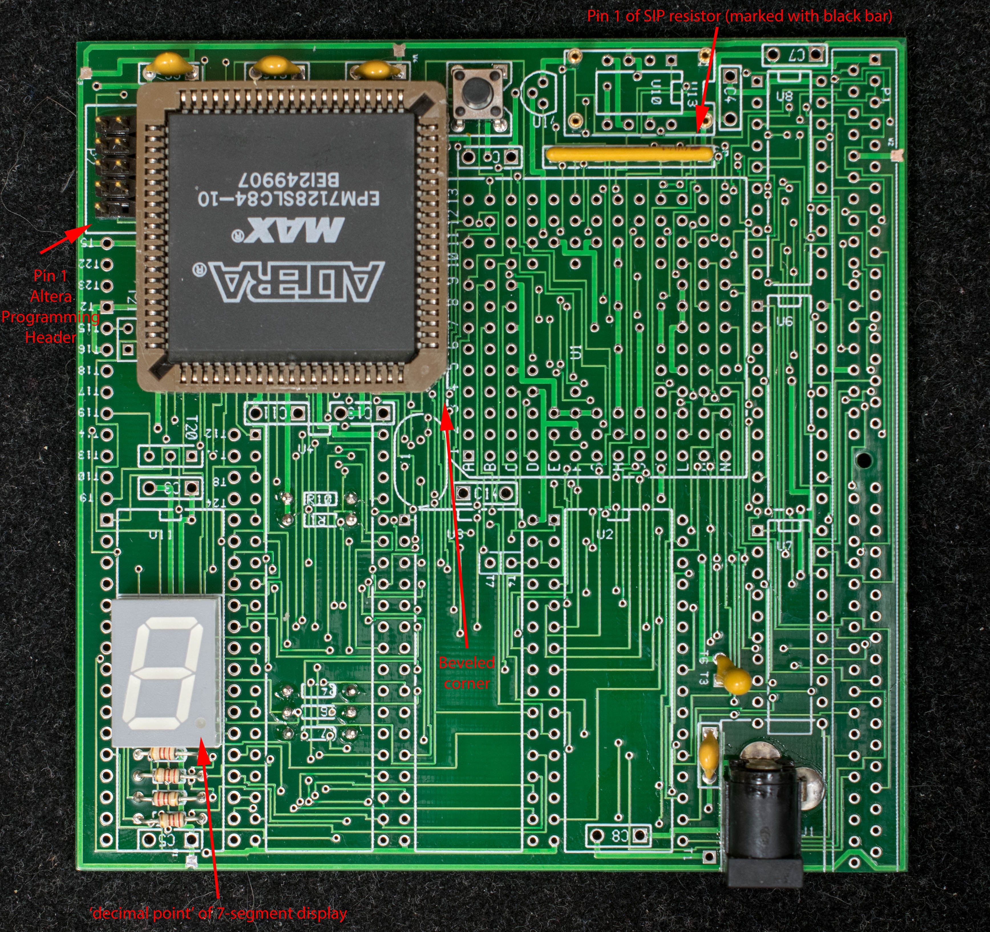
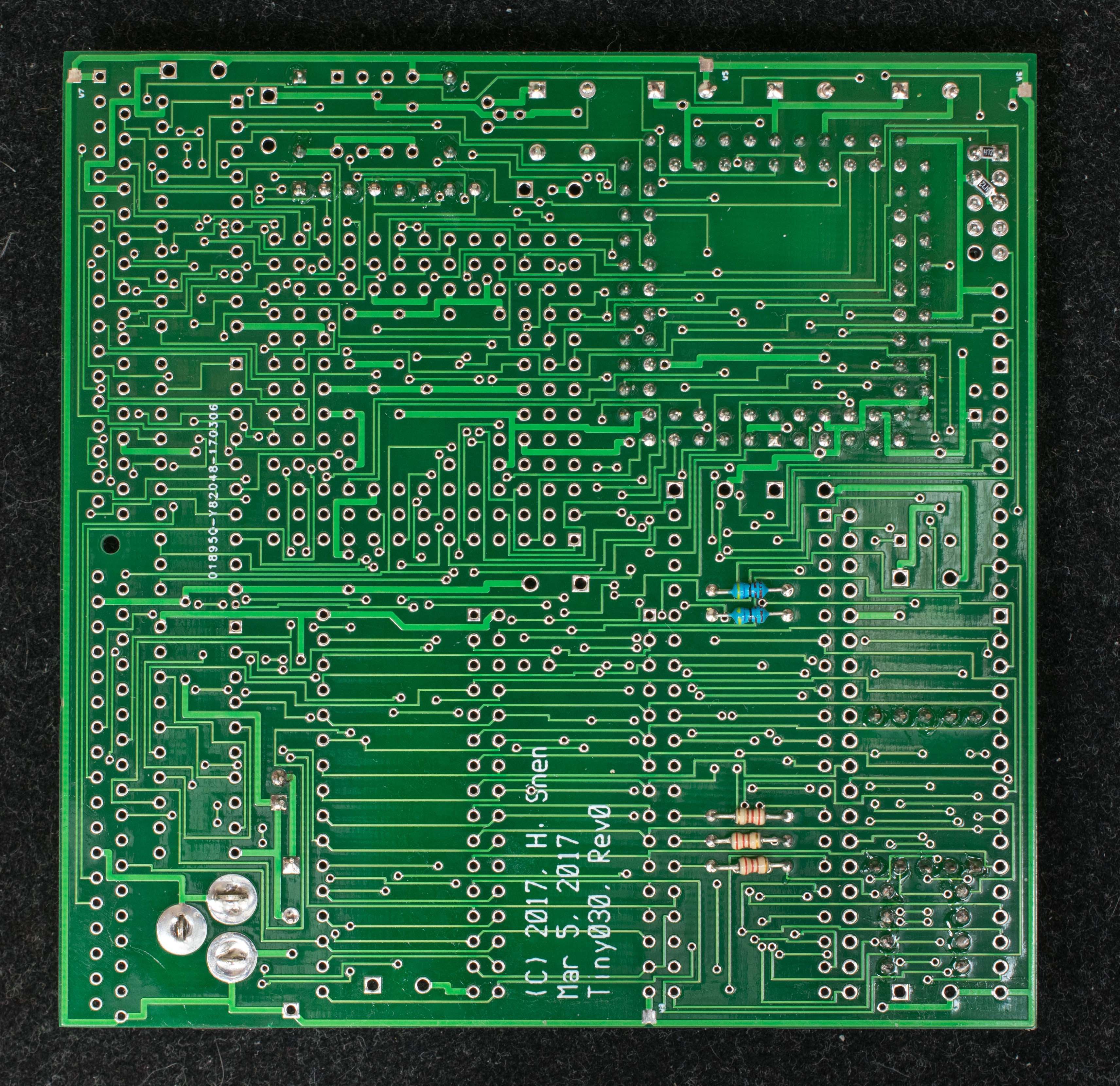
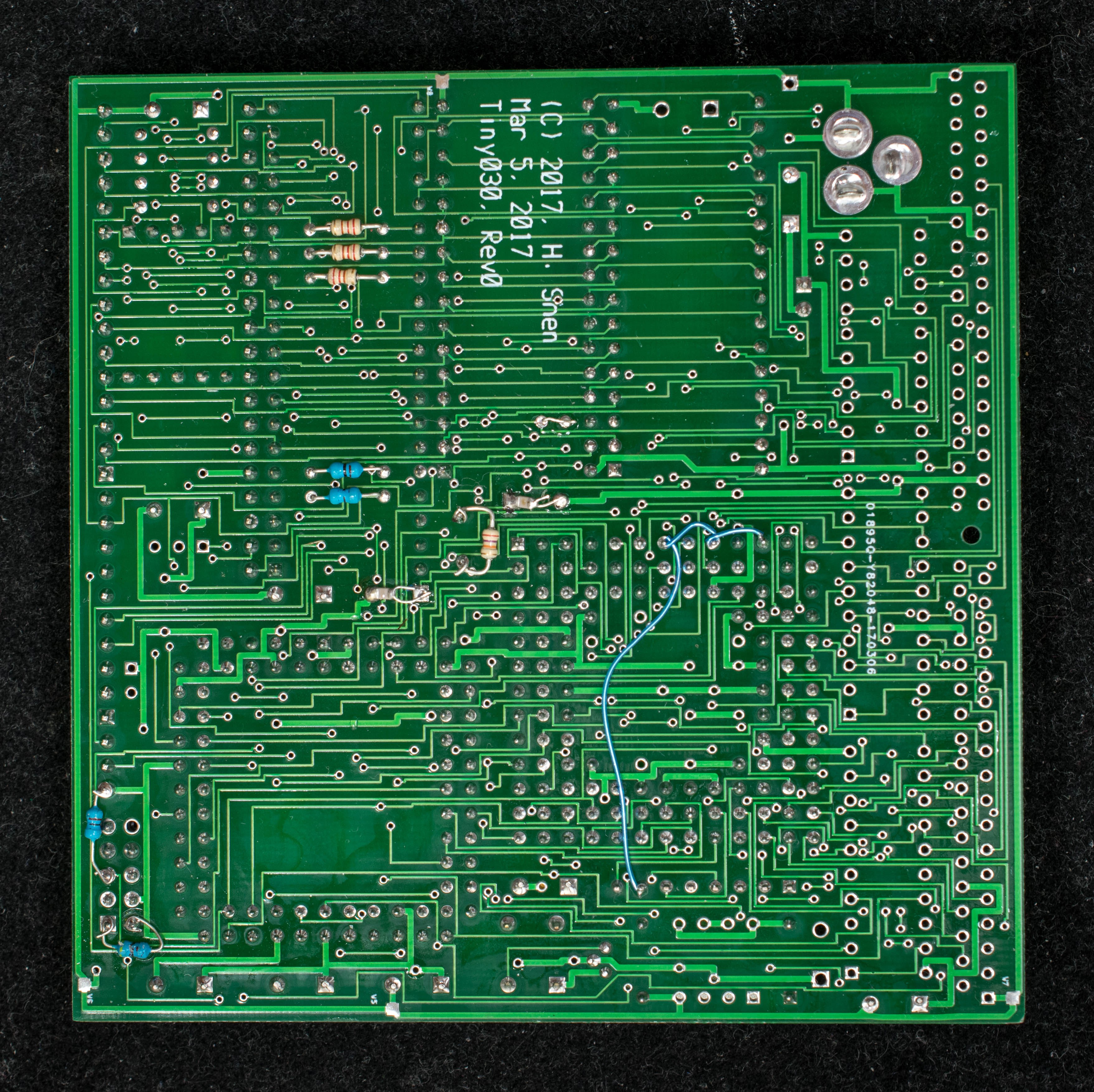
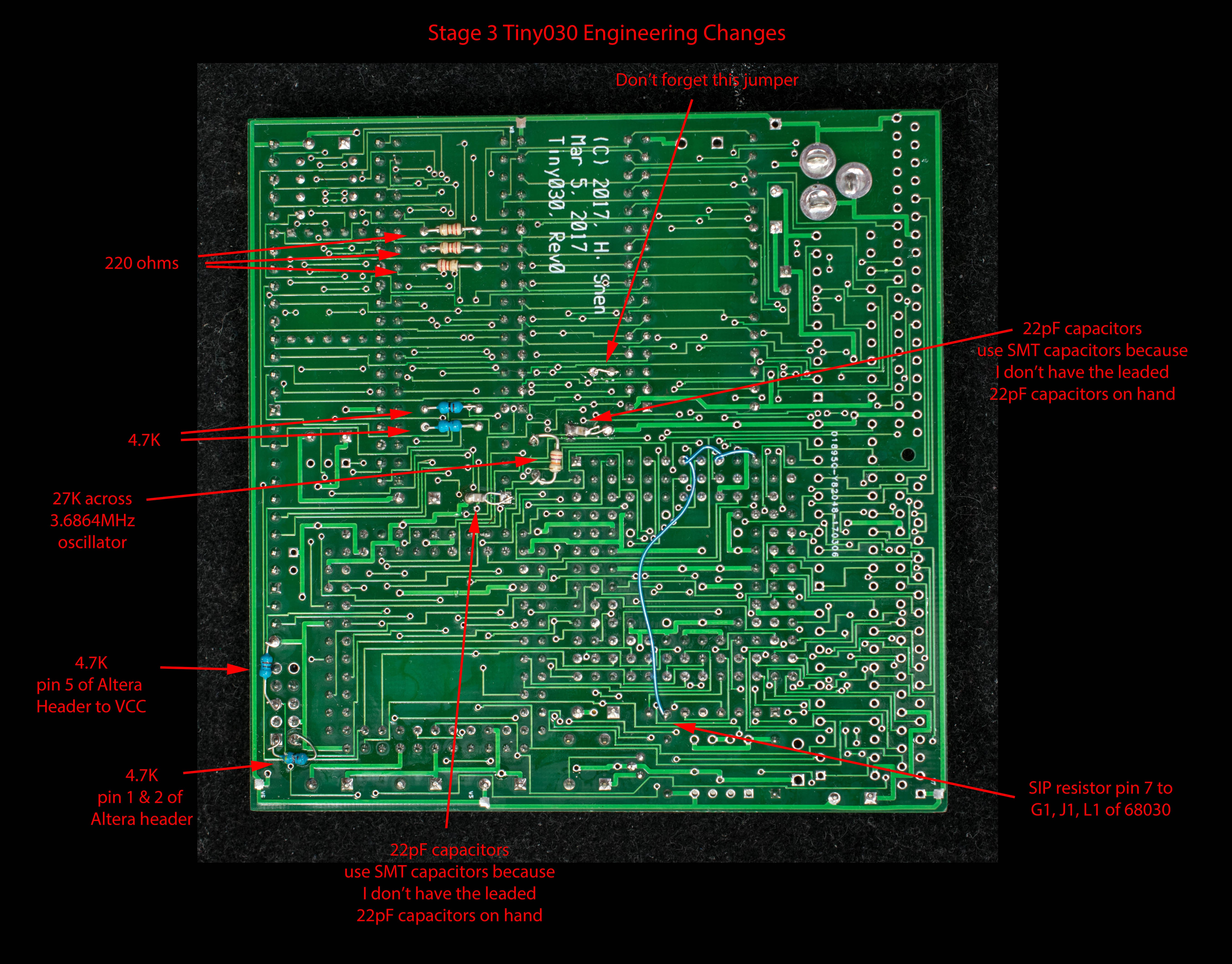
 Picture below shows the location of two 22pF capacitors. I do not have the leaded capacitors, so I substitute two SMT 22pF capacitors on the solder side of the pc board.


 Keith
Keith
Thanks for your feedbacks. I added links in Tiny030 project page to Tiny030 homepage as well as CB030 homepage.
Getting retro parts is a big challenge especially having consistent, steady supplies over a period of time. Even when parts are available, the cost and qualities can change quickly.