 Plasmode
-
1Building Instruction for Stage 3 of Tiny030
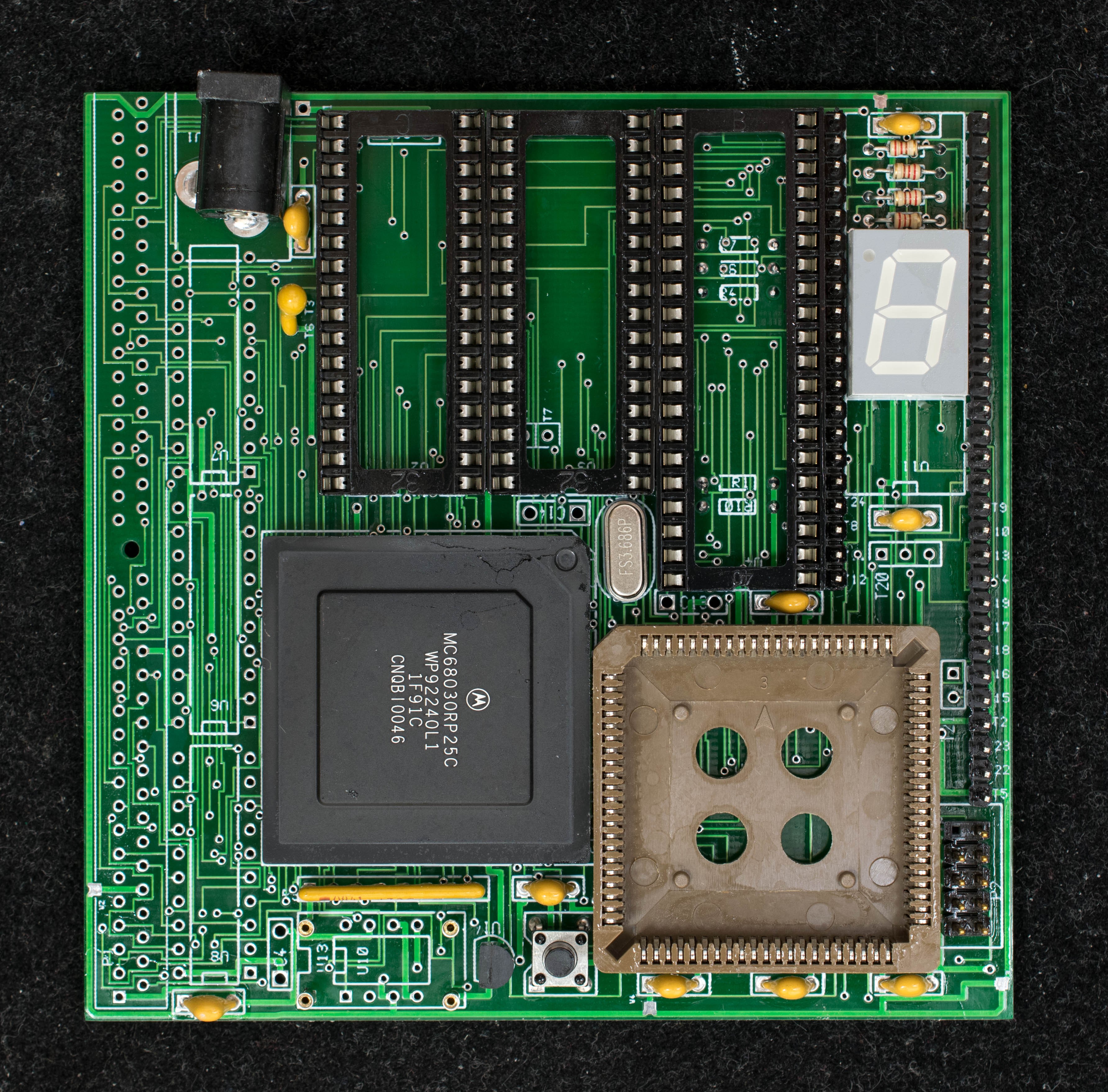
There are lots of manual wires in Stage 2. It is meant to help me designing a revised Tiny030 board. If you are working with rev 0 pc board, you may want to do Stage 1 to check out CPLD functionalities, skip over Stage 2 and follow this Stage 3 Instruction. Or if you are confident about the CPLD, you can start with this instruction and skips over stage 1 and stage 2. Tiny030 pc board needs minor engineering change just for stage 3. 3 extra resistors are needed and 3 extra wires are needed. The three pictures below show the component side of Tiny030 at stage 3, solder side, and lastly populated board.
![]()
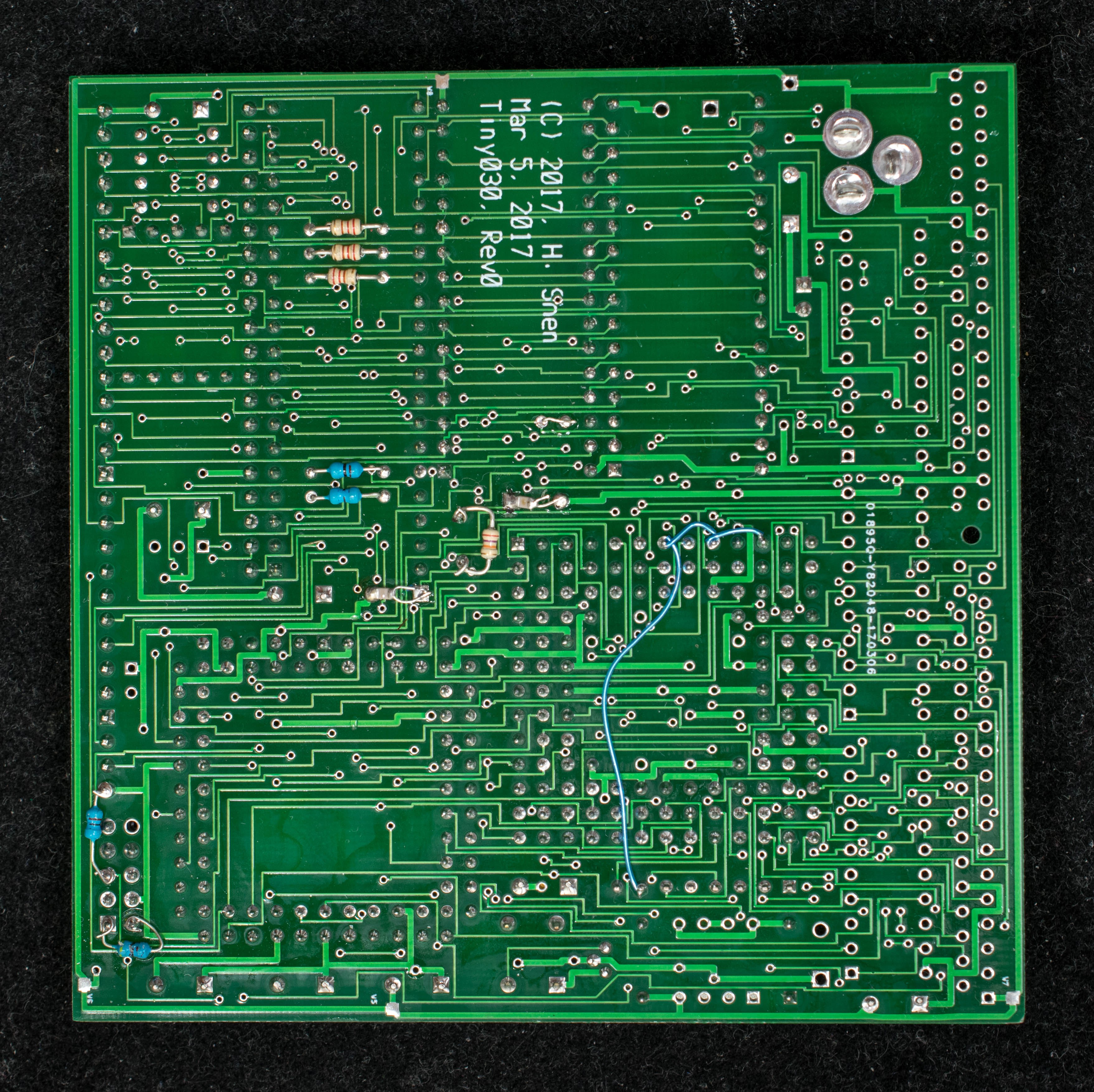
![]()
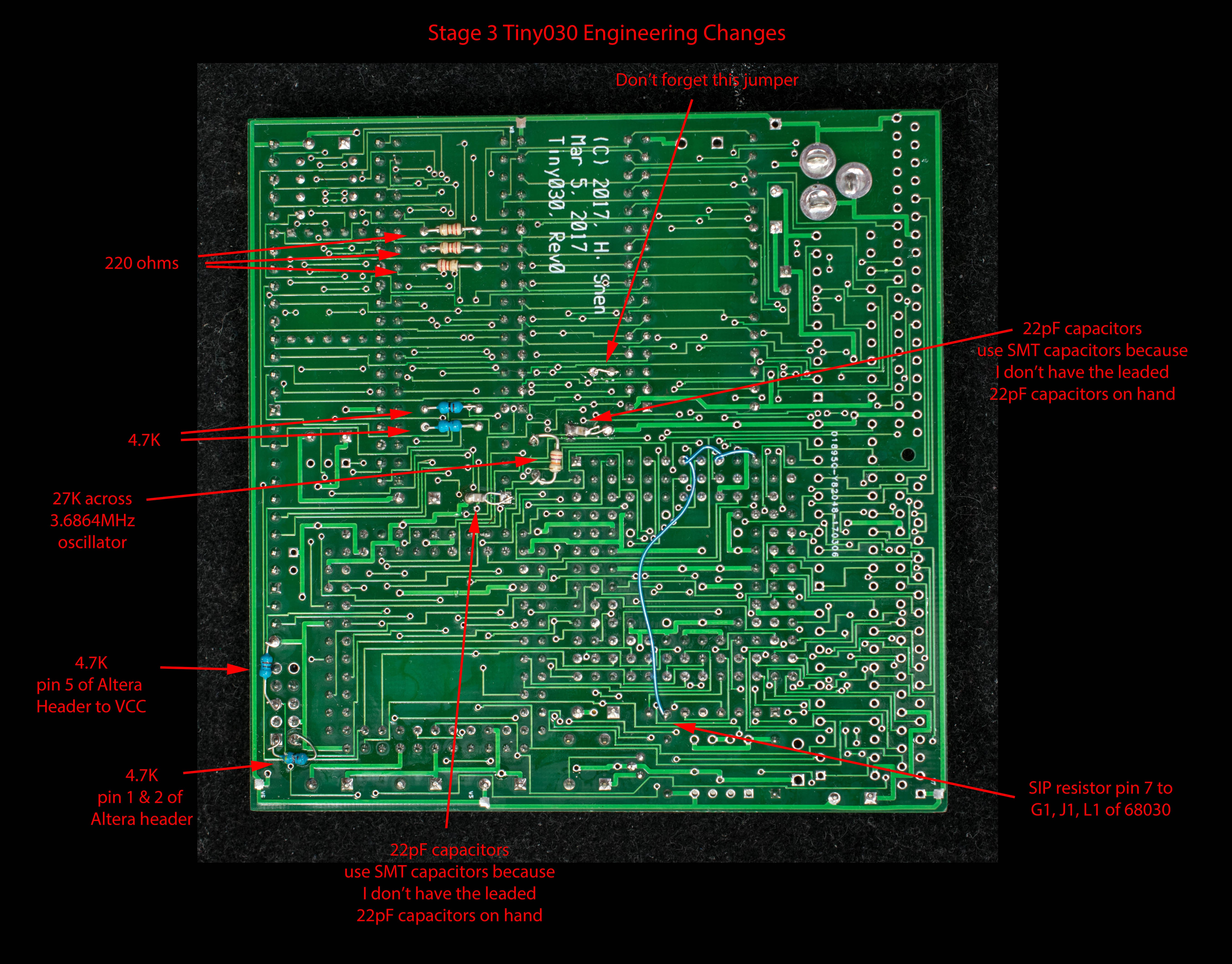
![]() Picture below shows the location of two 22pF capacitors. I do not have the leaded capacitors, so I substitute two SMT 22pF capacitors on the solder side of the pc board.
Picture below shows the location of two 22pF capacitors. I do not have the leaded capacitors, so I substitute two SMT 22pF capacitors on the solder side of the pc board.![]()
Picture below show the engineering changes required for Stage 3 Tiny030
![]()
The CPLD equations, ROM monitor, EhBASIC, and memory diagnostic described in stage 3 projects all work with this board.
 Picture below shows the location of two 22pF capacitors. I do not have the leaded capacitors, so I substitute two SMT 22pF capacitors on the solder side of the pc board.
Discussions
Become a Hackaday.io Member
Create an account to leave a comment. Already have an account? Log In.