-
Untethered!
12/15/2019 at 14:57 • 0 commentsAs of yesterday, DEVROM itself can detect a memory card during reset. When detected it will continue to boot from there instead of jumping to the built-in main menu. This means you don't need the Arduino route anymore when playing with the expander.
Naturally everything still needs refinements. But from here we can theoretically bootstrap an entire new system without ever updating the EPROM again, and without being tethered to a laptop/PC.
Some unrelated but noteworthy recent updates:- Preliminary interrupt support is now available (vIRQ)
- We have the ROM files discoverable with a new function: SYS_ReadRomDir. With this we can iterate over the built-in files and get their ROM address for reading. I can see this become useful in a simple command line shell. Or for making libraries.
- TinyBASIC now accepts hexadecimal numbers ($....) in expressions. This could be squeezed in without sacrificing free bytes.
-
First conversation with SDCard
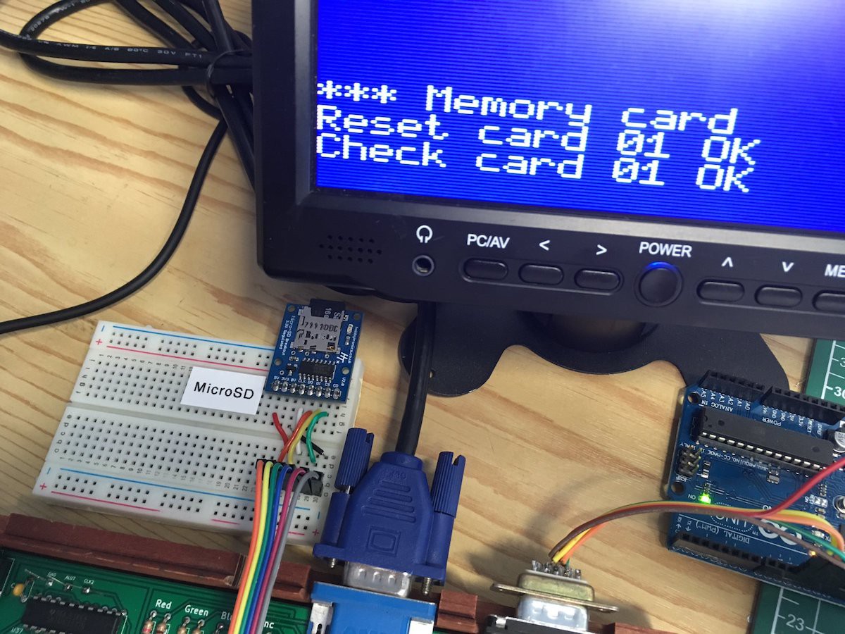
09/01/2019 at 13:04 • 0 commentsFirst messages exchanged with a physical memory card. "Reset" (aka CMD0) puts the card in SPI mode. "Version" (aka CMD8) is the canonical method to check if the card is ok. The reply bytes come from the card and are the expected value (0x01).
![]()
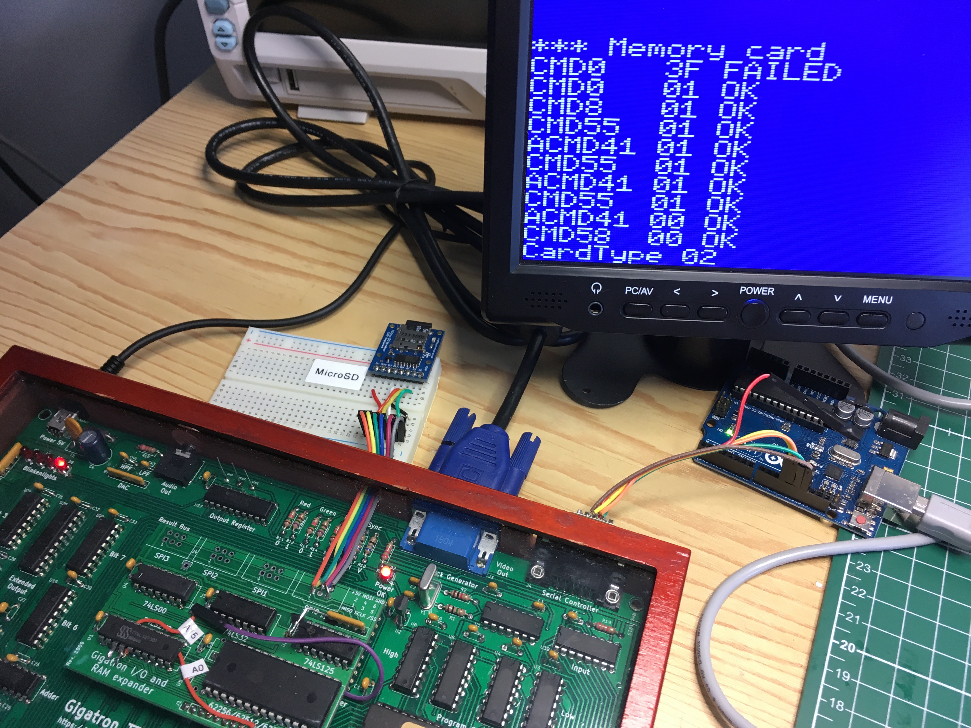
A few hours later we can correctly initialise the card and detect the card type:
![]()
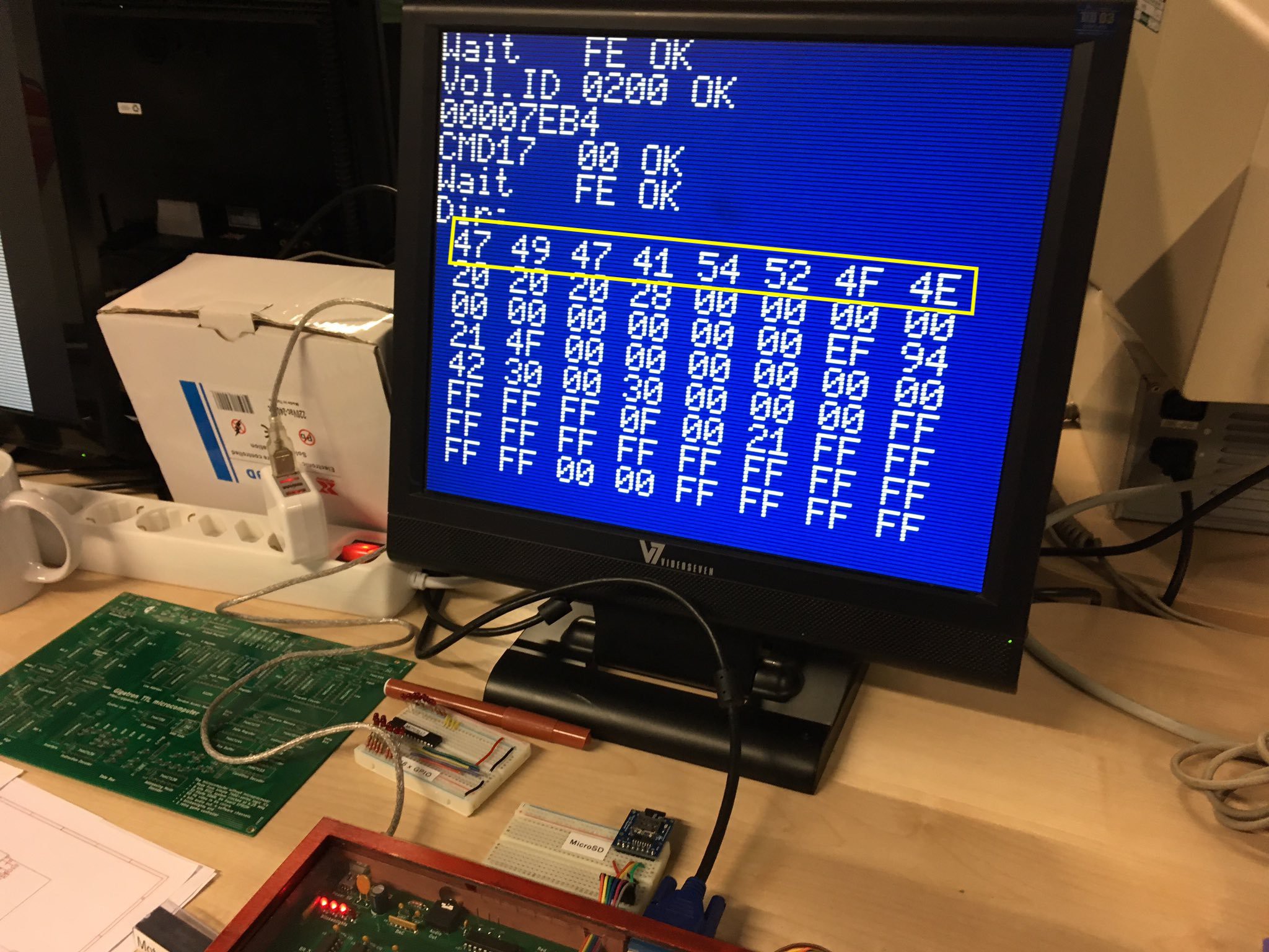
Update: And here's the root directory. It takes a bit of 32-bit arithmetic to locate it correctly. You can see the volume label in the first slot. It reads "GIGATRON".
![]()
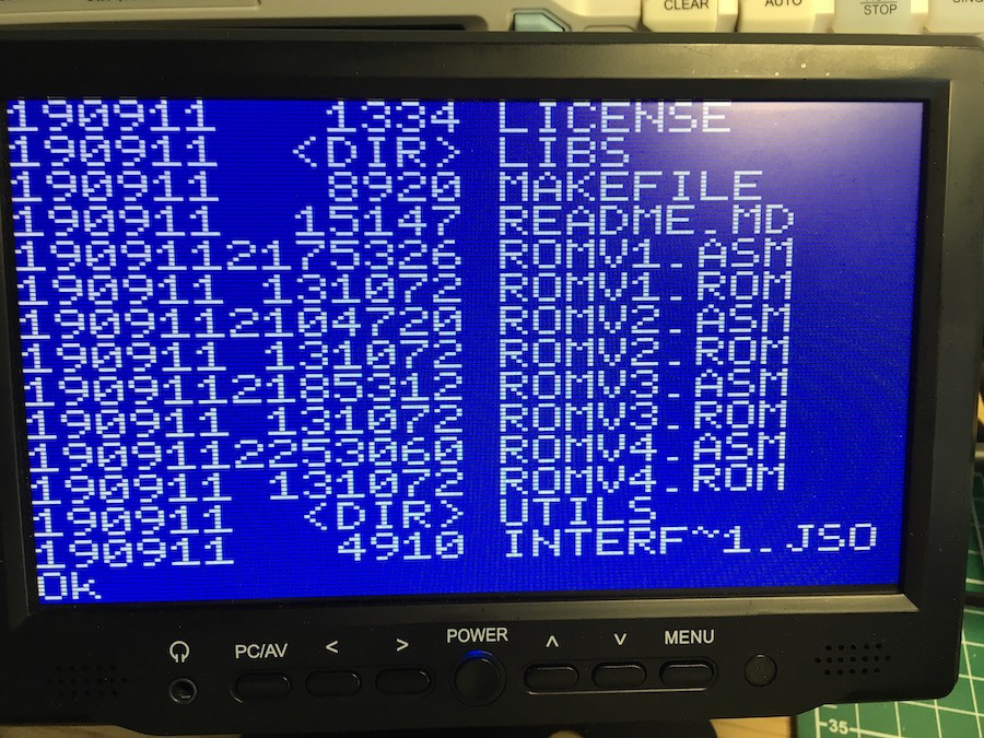
Update 2: and here is a proper listing:
![]()
-
Roadmap for Gigatron expander
05/19/2019 at 21:02 • 0 commentsAs usual, the hardware turns out to be easier than the software. So where can we take this now that we've covered the hardware support for SPI, memory cards and 128K of banked memory? It's clear to me that this subproject must aim for proper FAT filesystem R/W compatibility. Not some halfway solution with image files. But I really don't feel like coding it from scratch in vCPU. @roelh has suggested FatFs. But that needs a C compiler...
![]() But I don't feel like porting FAT support from C either. Are we stuck?
But I don't feel like porting FAT support from C either. Are we stuck?In Seattle I briefly met with [Pat Gavlin]. A month later he surprised the world by announcing that he's retargeted LCC to the Gigatron vCPU. Just wow.... HaD covered it recently. This is a proper ANSI C compiler (C89) with fancy stuff such as strength reduction and common subexpression elimination. One of the great things about Pat's backend is not just that it targets vCPU, but moreover that it overcomes the Gigatron's non-linear memory address space: C programs "see" a fairly standard environment. Currently we're still ironing out the bugs that you inevitably bump into when compiling larger programs. And we're working on the C library. For example, printf is working already.
Now a roadmap starts to sketch itself:
-
Full recovery & mission accomplished
03/31/2019 at 14:34 • 6 commentsAfter returning from the VCF, three things needed recovery: 1. the jetlag, 2. a stomach bug and 3. the little brittle breadboard with dummy peripherals. Today it all worked again. And even better: the SPI test routines now load from my laptop into the Gigatron (through an Arduino Uno that acts as a bridge). Now I don't have to type in hex codes anymore, and that should help with our follow-up project: talking to the MicroSD card.
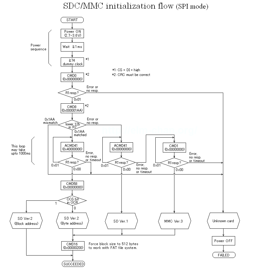
A glimpse of the mountain that is now ahead of us:
![]()
And that's just for initialising the card, so you know you can talk to it. The best thing of this? This reassuring quote:
"This is just one example of such an initialization sequence. [...] It’s possible that it may work or not depending on the type of card you use and on its manufacturer. Other similar such flowcharts exist. [...] Most of the times, you will have to try to implement several of them until you will get it to work"
Now imagine deciphering the FAT file system on top of that. This can easily take the remainder of the year to get right.
Down the rabbit hole we go...
![]()
Source: http://www.mayumitokuda.com/2d-illustration/art-stuff/7246032
-
VCF inspiration
03/26/2019 at 18:55 • 2 commentsI needed some inspiration before resuming with the I/O expander, so this weekend I visited the Vintage Computer Festival in Seattle.
![]()
It's only a 10 hour flight. There are ways to deal with that, such as watching 3.5 movies per leg.
![]()
Seattle is a friendly place and great for playing tourist.
![]()
The Aquarium is nice too. But why does its restaurant serve fish?
![]()
The festival was held at the late Paul Allen's Living Computers Museum + Labs.
![]()
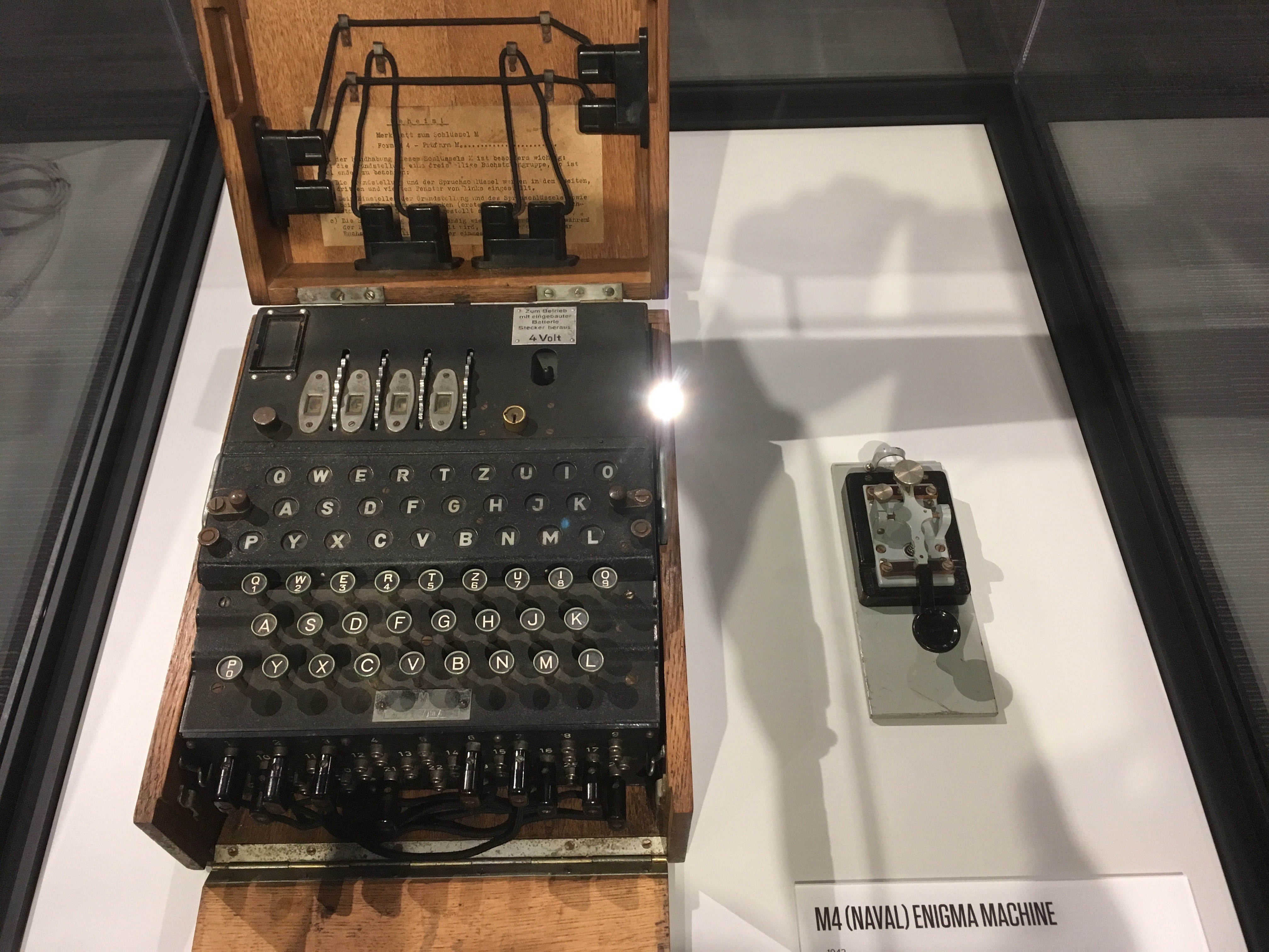
Every computer museum must have an Enigma machine of course.
![]()
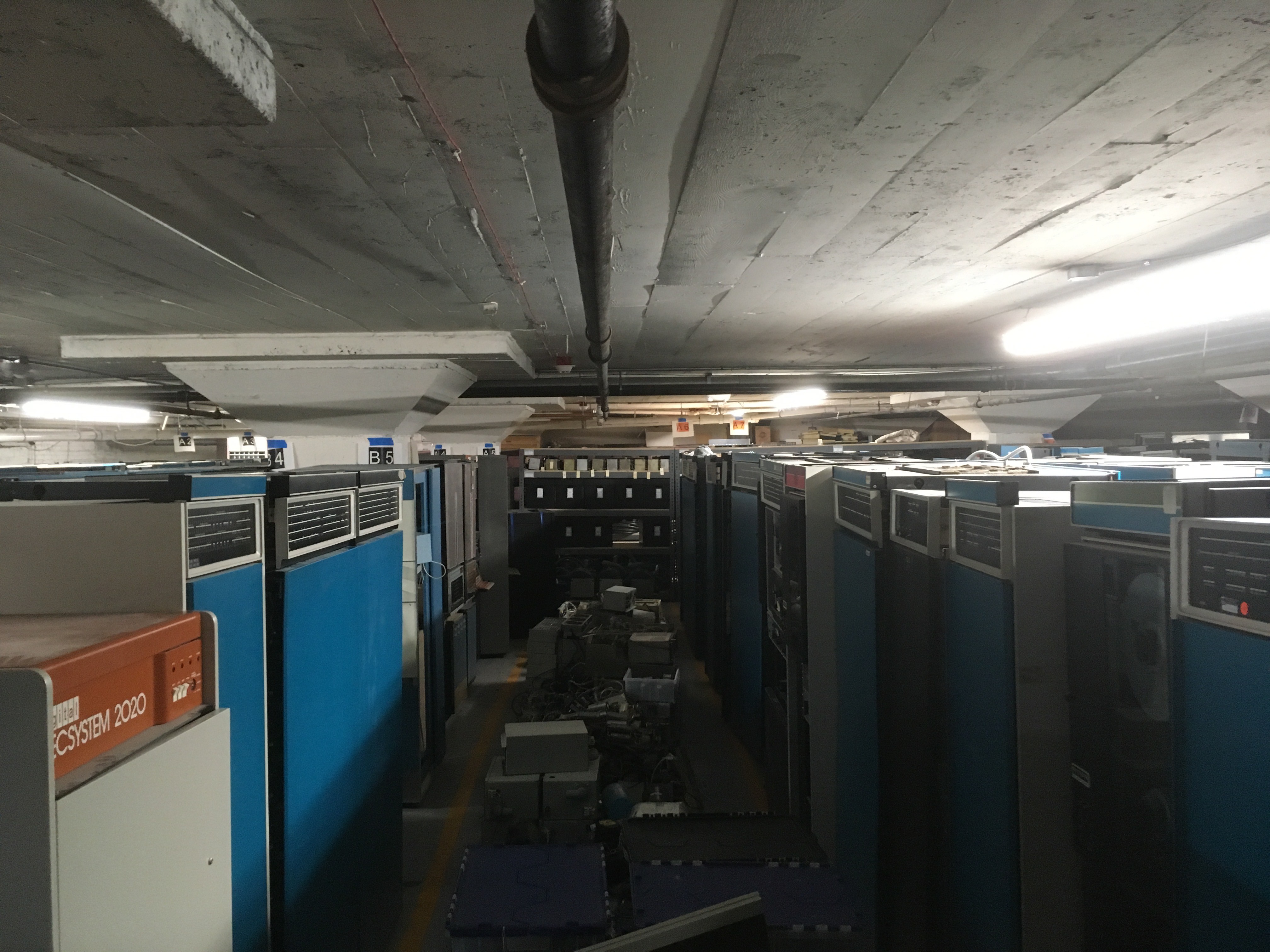
But how many PDP-10's does your museum have in its basement?
![]()
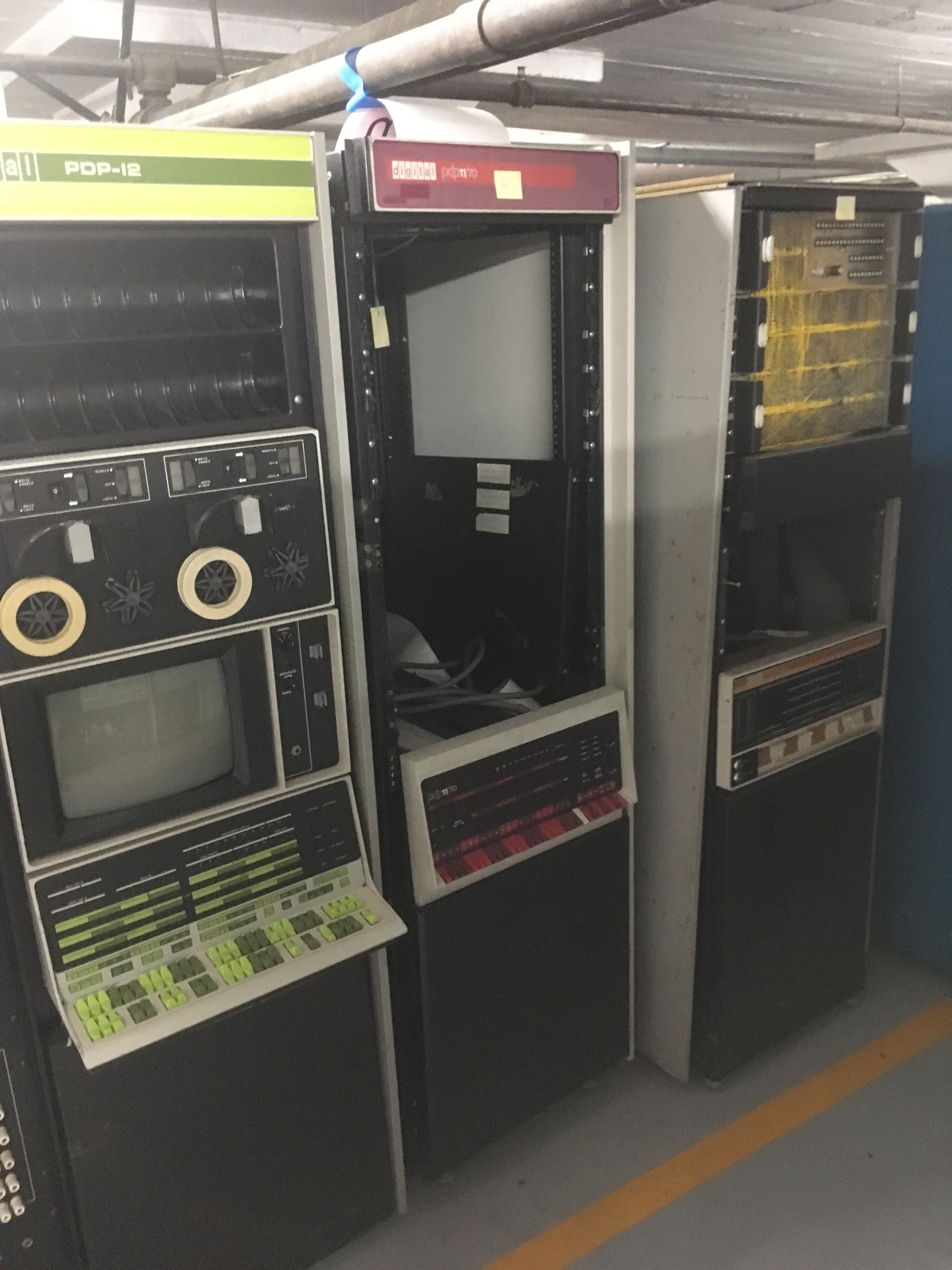
PDP units everywhere... Here some PDP-12, PDP-11 and PDP-8 processors and front panels.
![]()
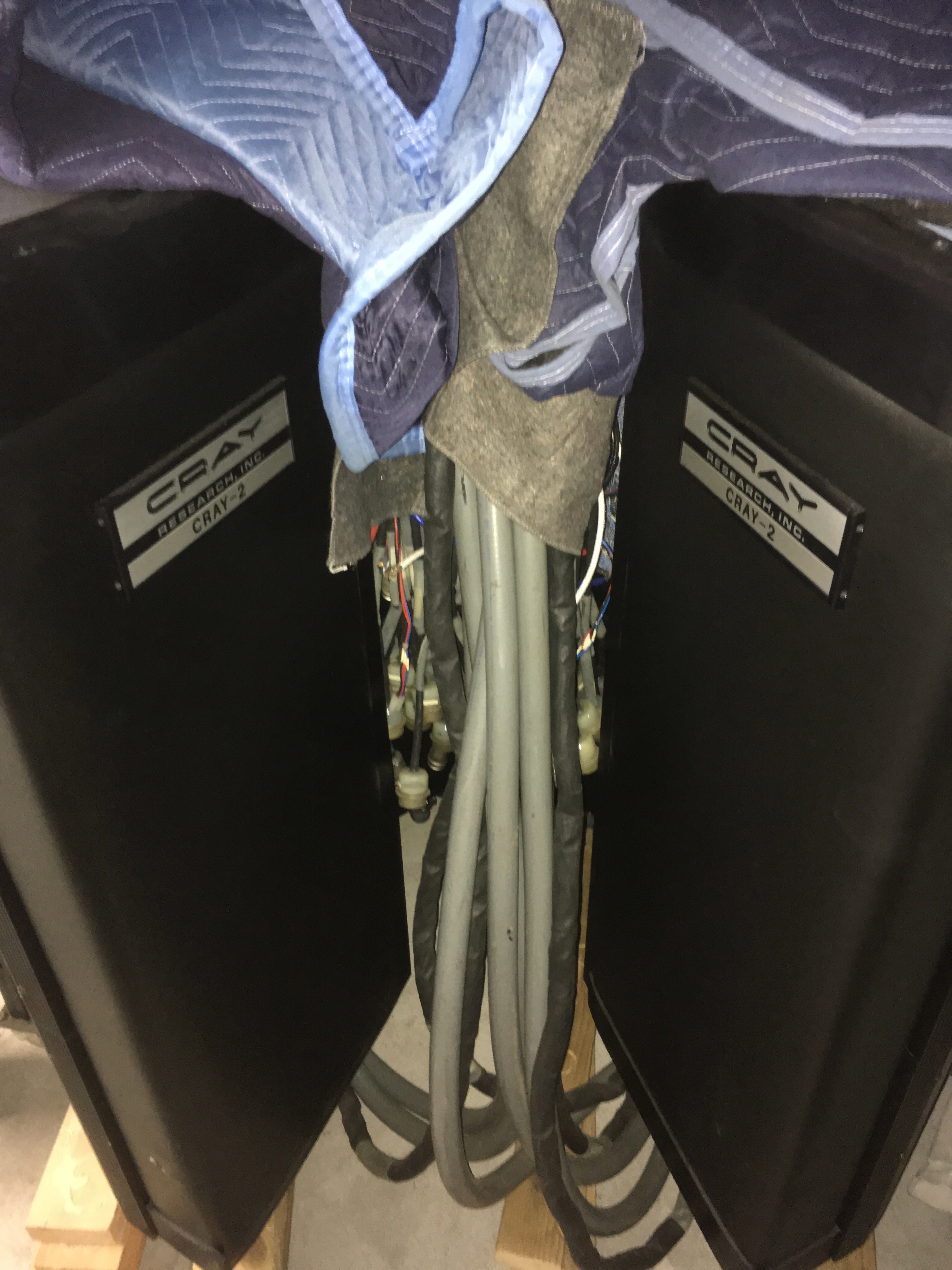
When you have a Cray-1 on the main floor just as a visitor's bench, the Cray-2 can sit in storage.
![]()
An original Apple 1 that needed some reprogramming. They have three such ultra rare machines on display, but none are even mentioned on the website...
![]()
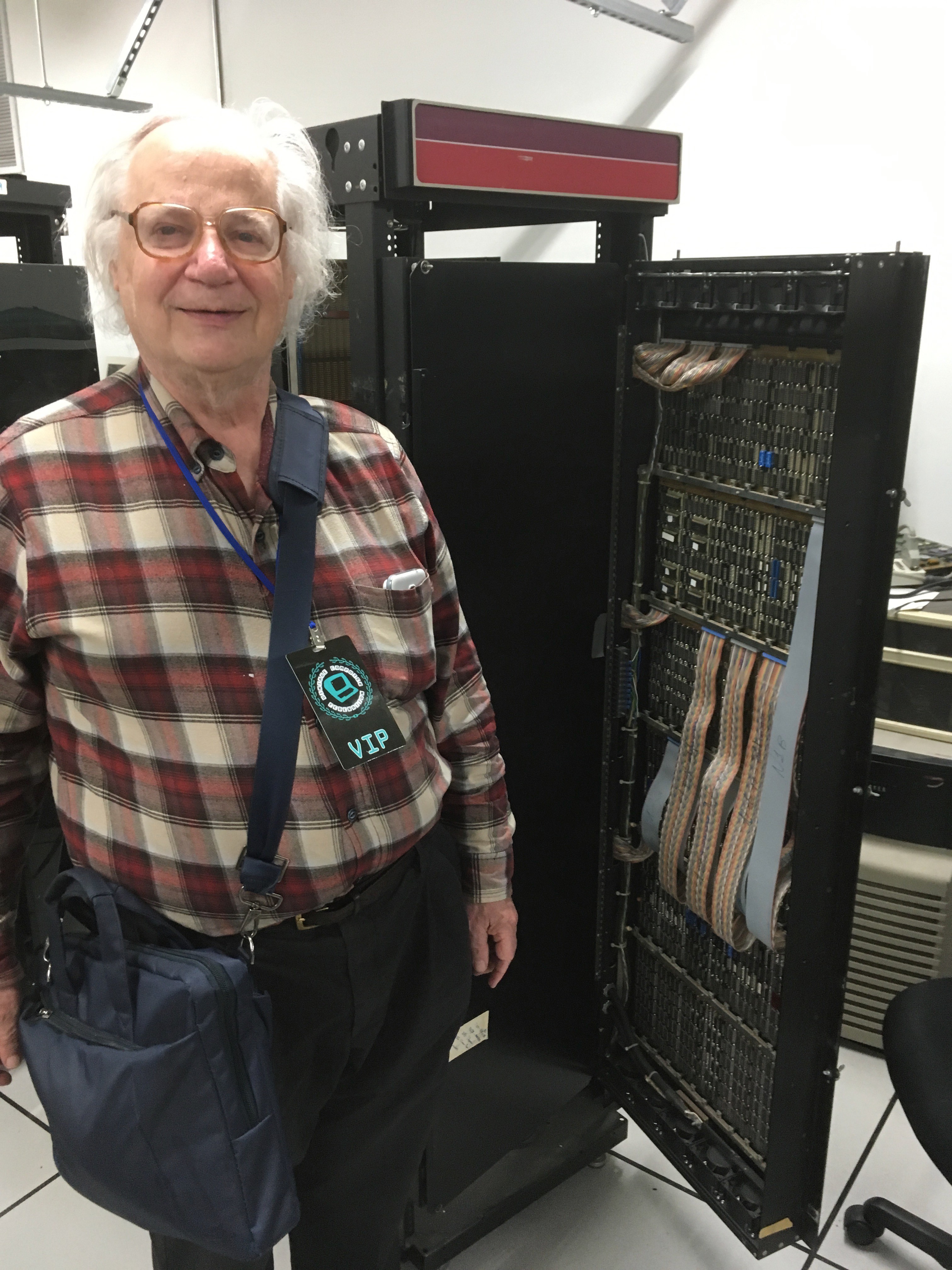
I found Richard Greenblatt and a couple of CADR aka LISP machines in the attic. It's part of what makes it a Living Museum I guess.
![]()
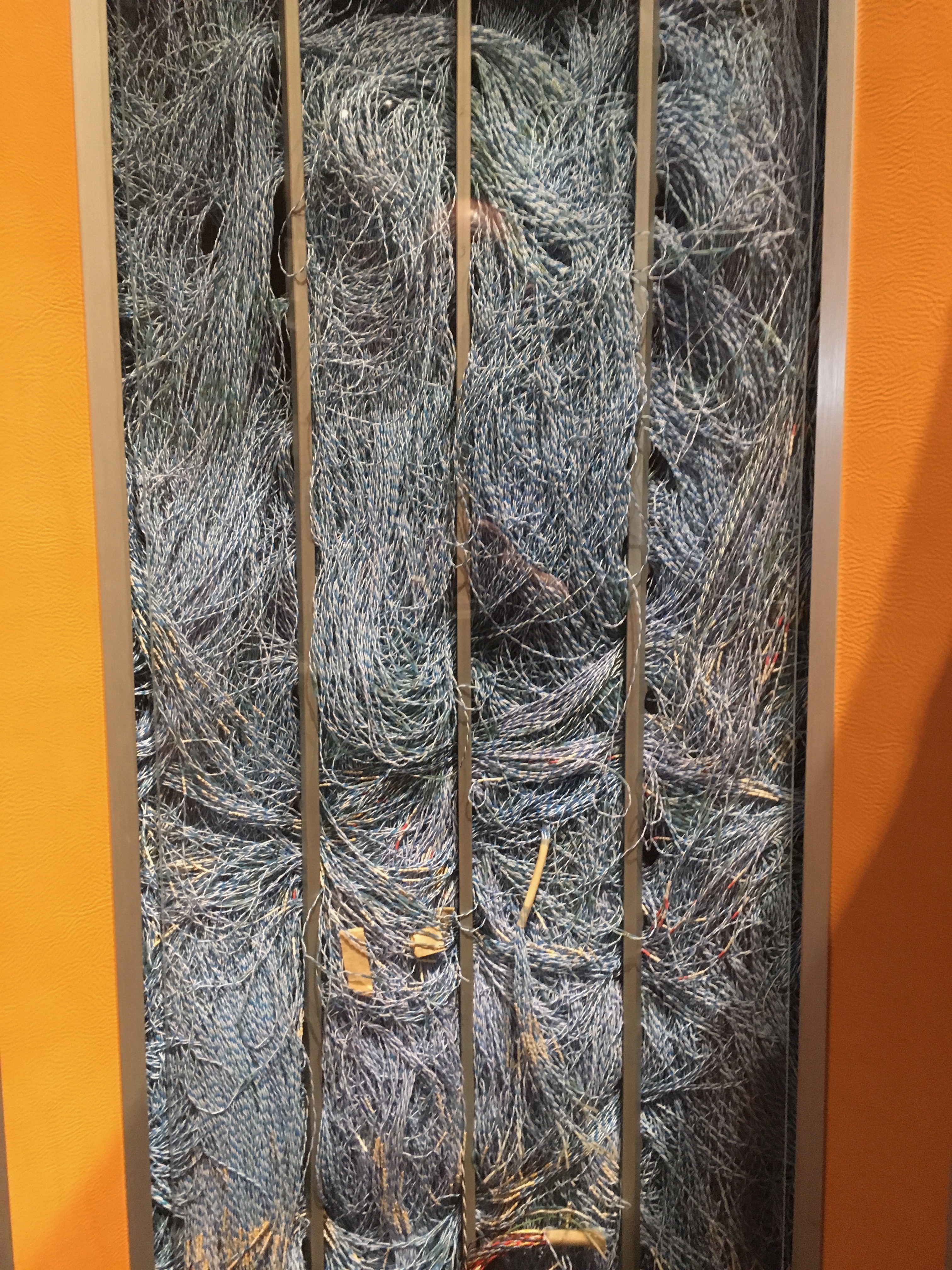
How the LISP machine is wired.
![]()
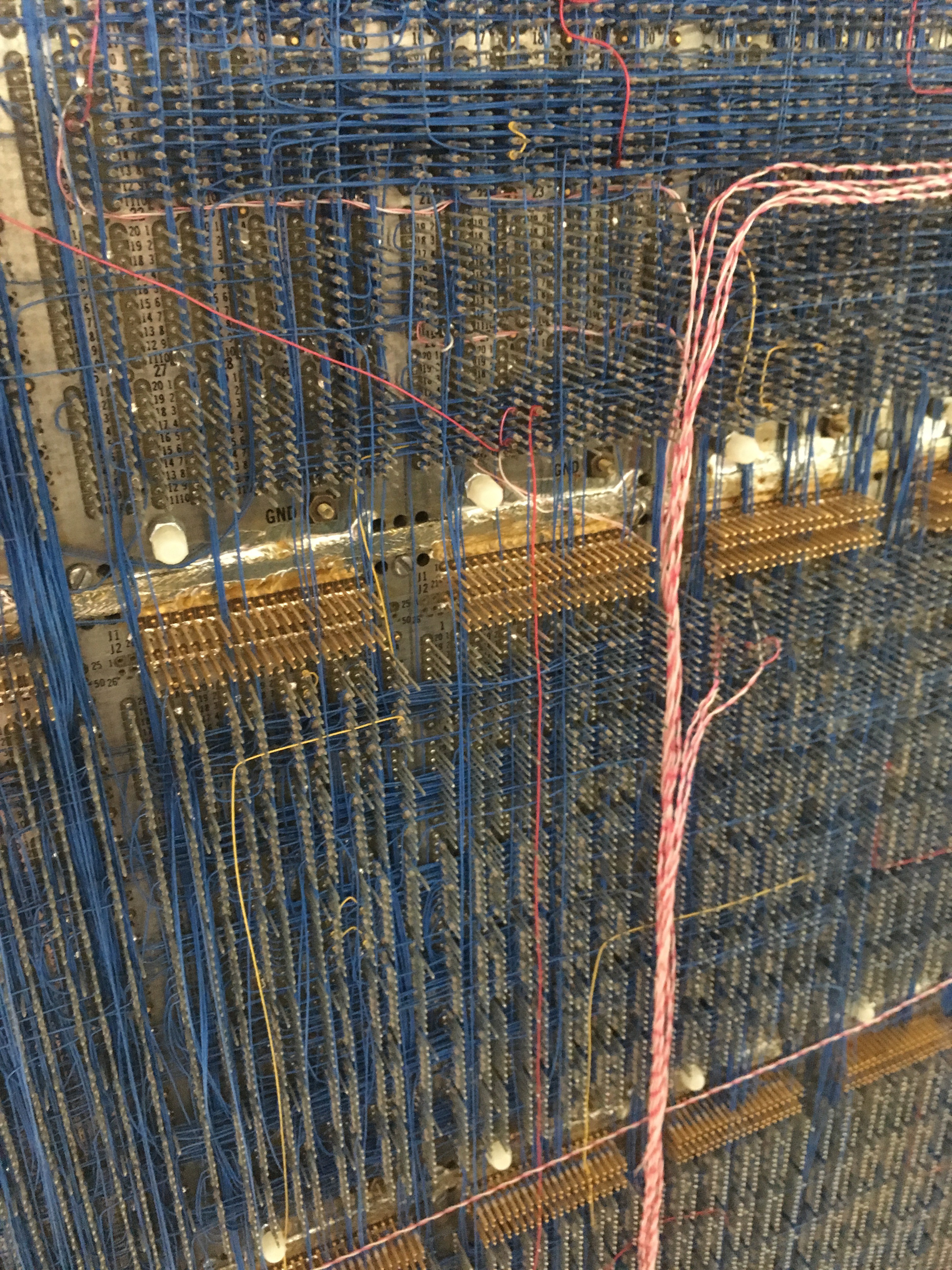
And how the Cray-1 is wired.
![]()
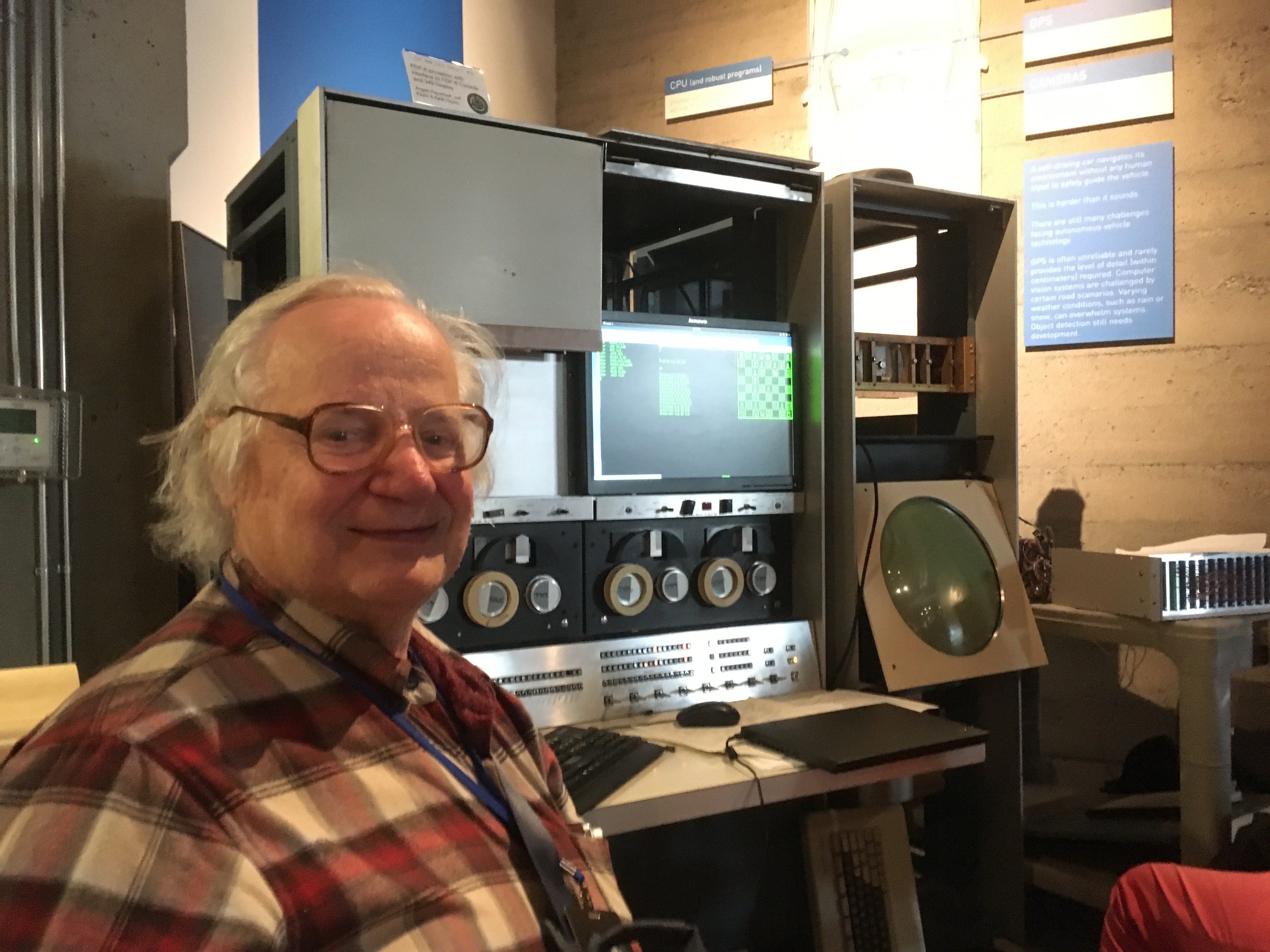
Richard and a PDP-6 front end, with his Mac Hack Six chess program running in the background.
![]()
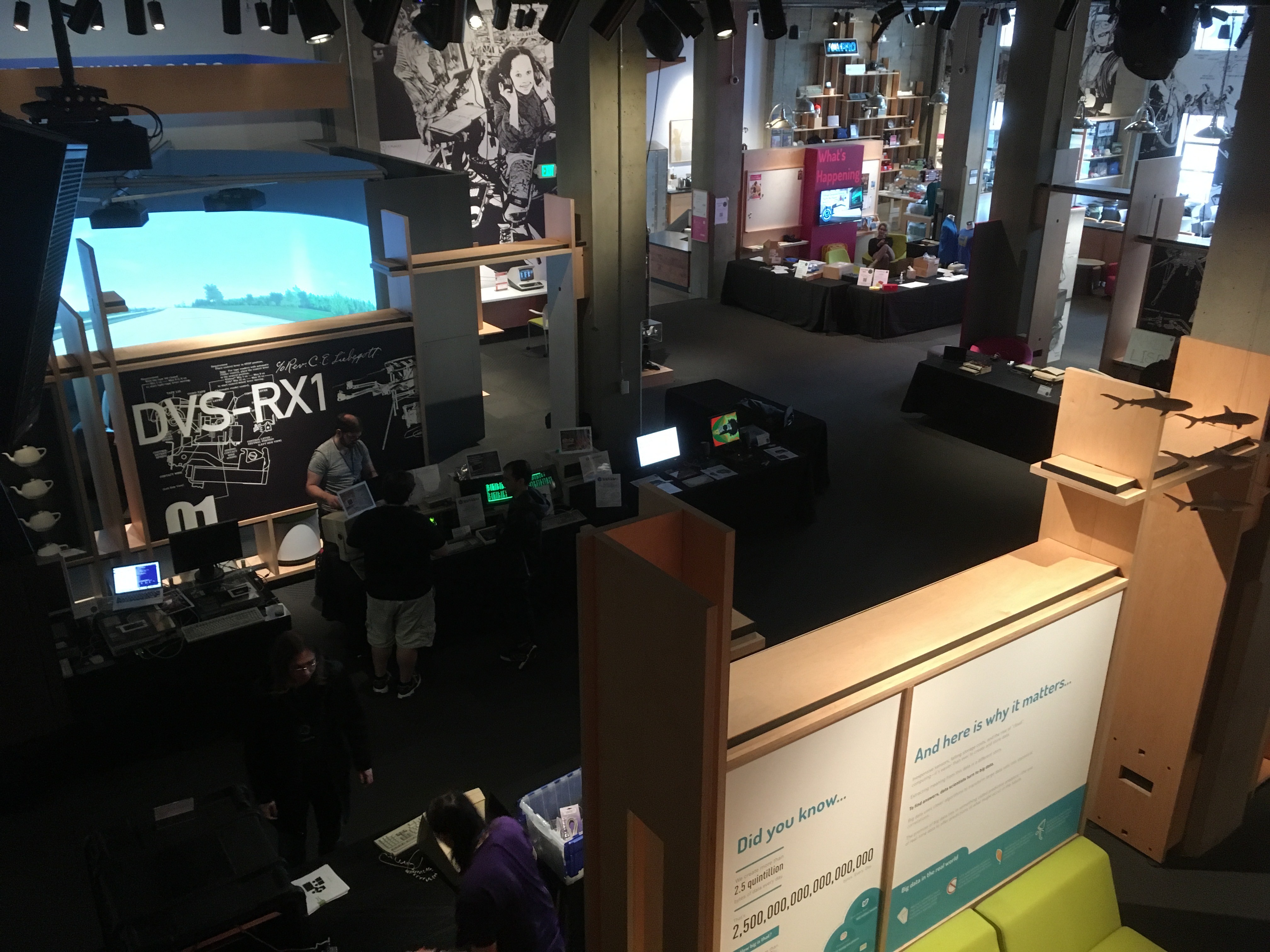
Part of the VCF show just before opening. You can see my exhibit of two Gigatrons in the center. I only brought one: the Gigatron that I'm using for the I/O expander project. The other I borrowed... believe it or not.... from the museum itself. How bizarre is that.
![]()
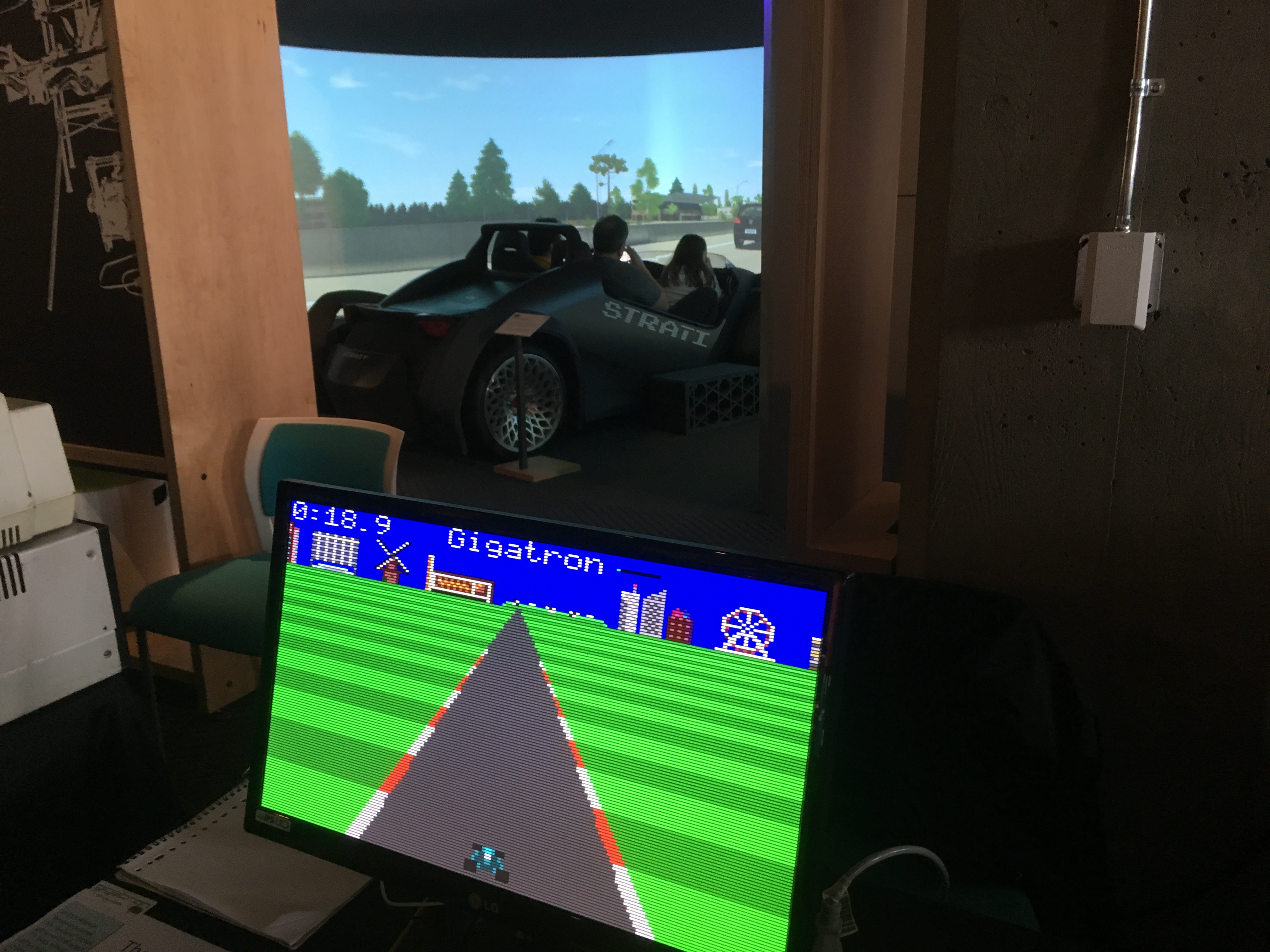
Driving simulator shootout. All right, we'll call it a draw.
![]()
I almost bought this laser videodisc, but it was bundled with the player and I didn't want that.
![]()
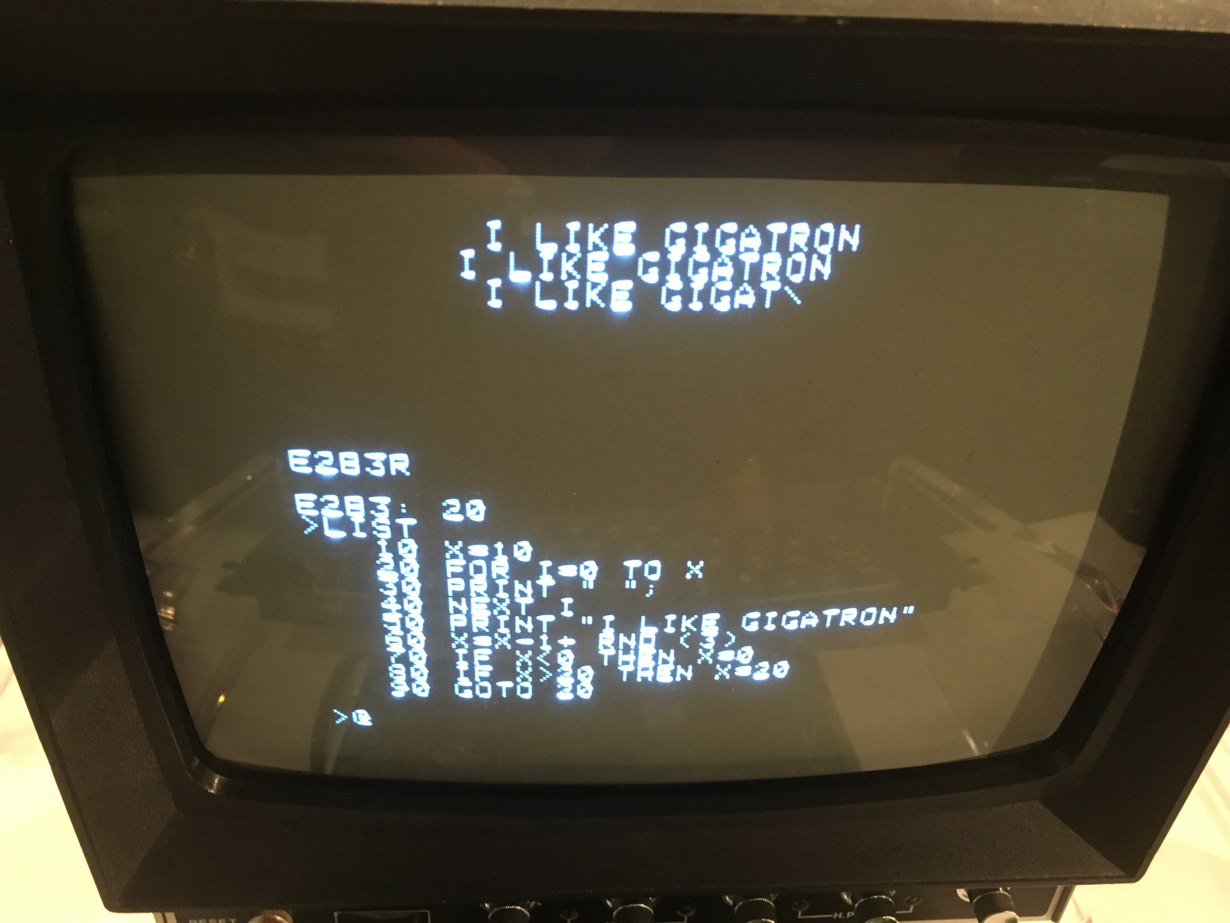
The result of all of this is a slightly improved version of the LED blinking program.
![]()
It controls 16 LEDs using the following SPI commands to the MCP23S17:
40 00 00 ; Set PORTA to all-output

40 01 00 ; Set PORTB to all-output

40 14 xx ; Send byte value xx to PORTA

40 15 xx ; Send byte value xx to PORTB
Blinking lights are essential for vintage computer shows, especially when your table is next to Oscar Vermeulen's fabulous mini PDP-replicas.
-
Success! Now we can have 512 GPIO pins
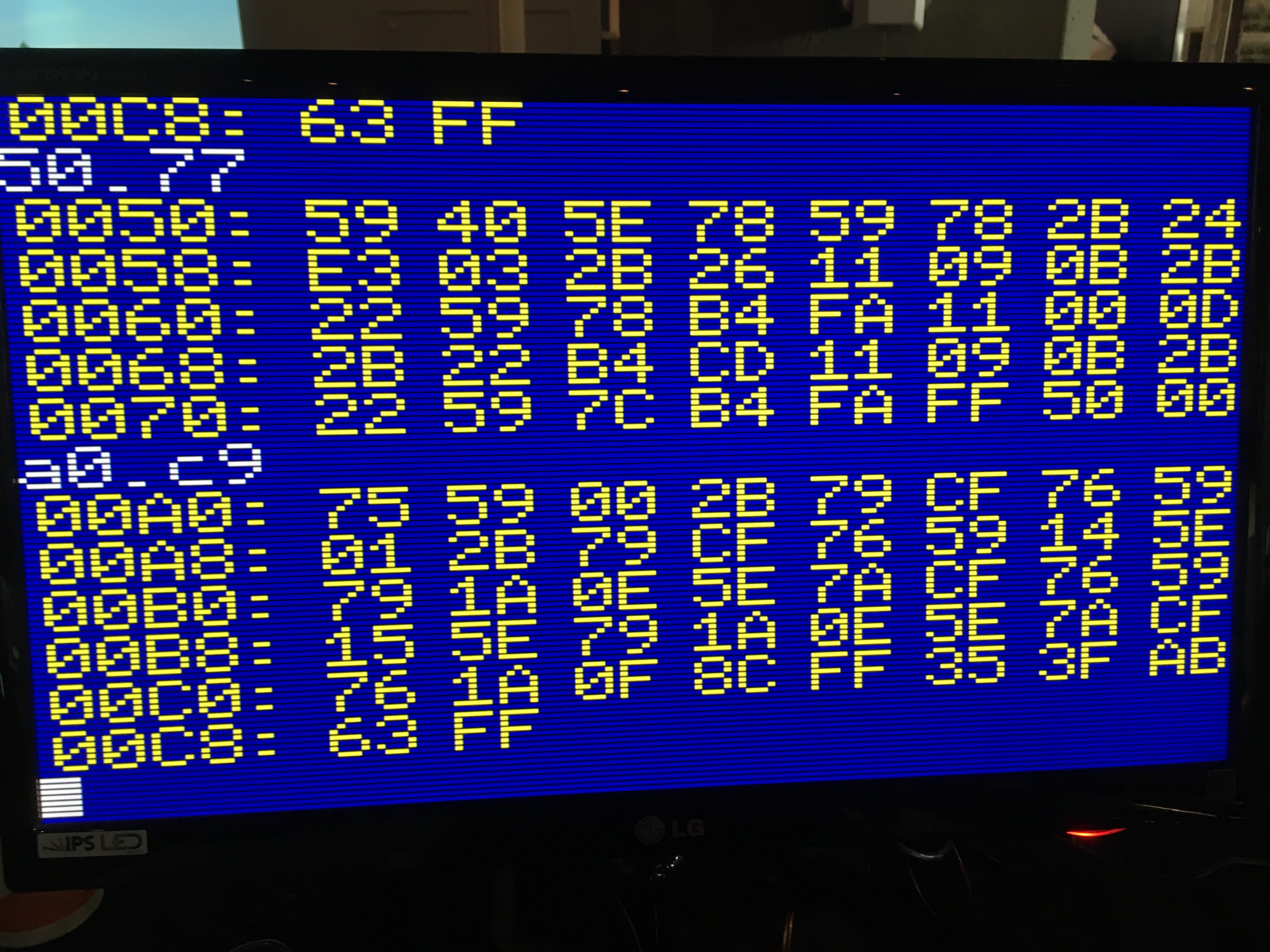
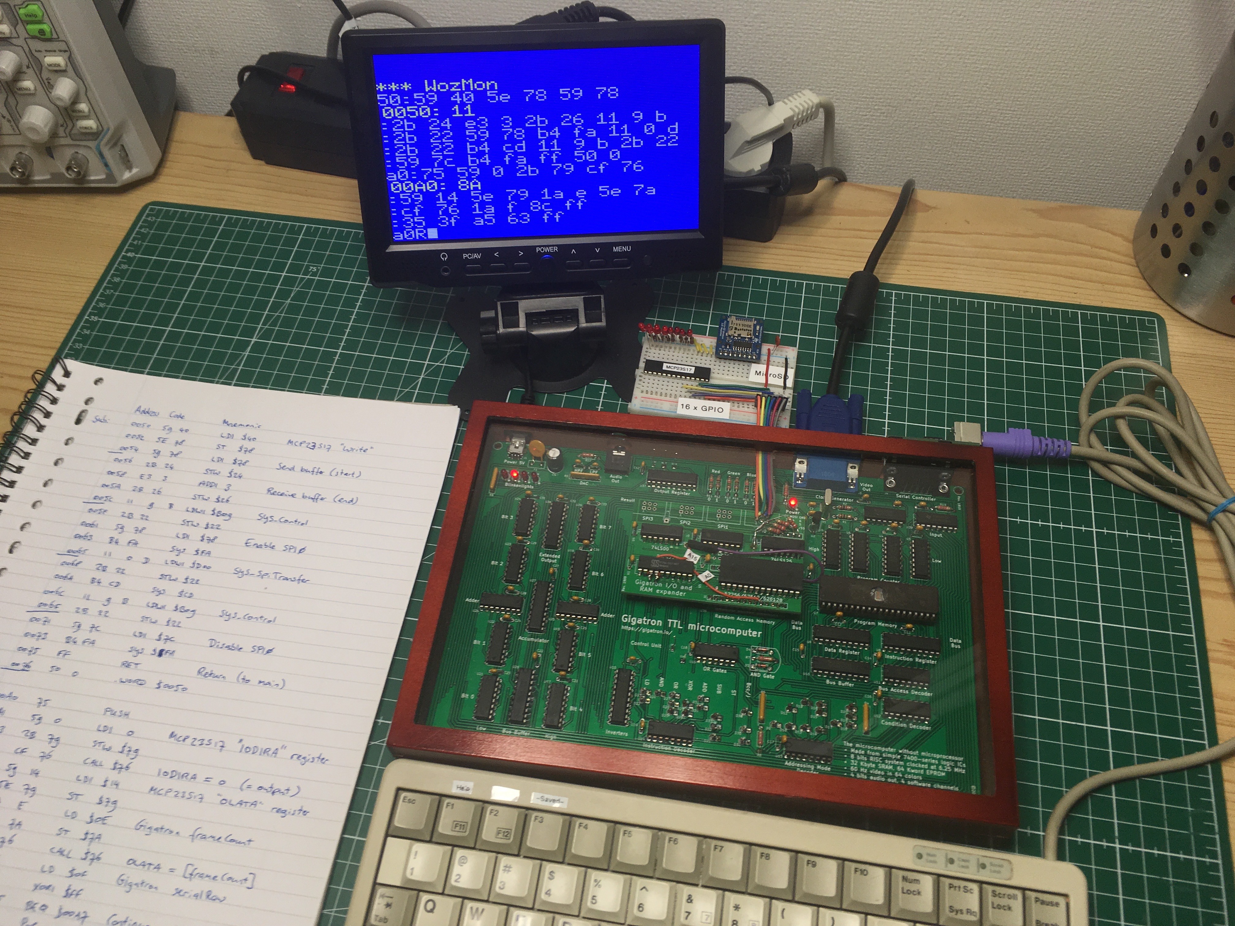
03/11/2019 at 23:51 • 0 commentsIn this video I control some GPIO pins over SPI from a Gigatron TTL computer with the expander prototype. The chip on the breadboard is an MCP23S17 16-bit I/O chip with SPI interface. Because this is the retro challenge RC2019/03, I wrote the test program on paper and toggled it in using the WozMon. Then I started filming:
It works the first time! The test program first configures 8 pins as outputs, and then continuously copies over the Gigatron's 60 Hz frame counter. There are two SPI commands involved:
40 00 00 ; Set PORTA to all-output

40 14 xx ; Send byte value xx to PORTA
It turns out this chip is addressable and can share select lines without causing contention on the MISO line: it keeps its SPI output in high-impedance unless addressed for reading. There are 3 pins for setting its hardware address, giving 8 addresses. We have 4 ports, so we can effortlessly hookup 4x8x16 = 512 GPIO pins...
The next step would be talking to an MicroSD card using the AdaFruit breakout board. (SparkFun has a similar one.) You can see it's already installed on the breadboard. These breakouts come with voltage level shifters, so they should work just like that.
![]()
-
Driving SPI with the WozMon
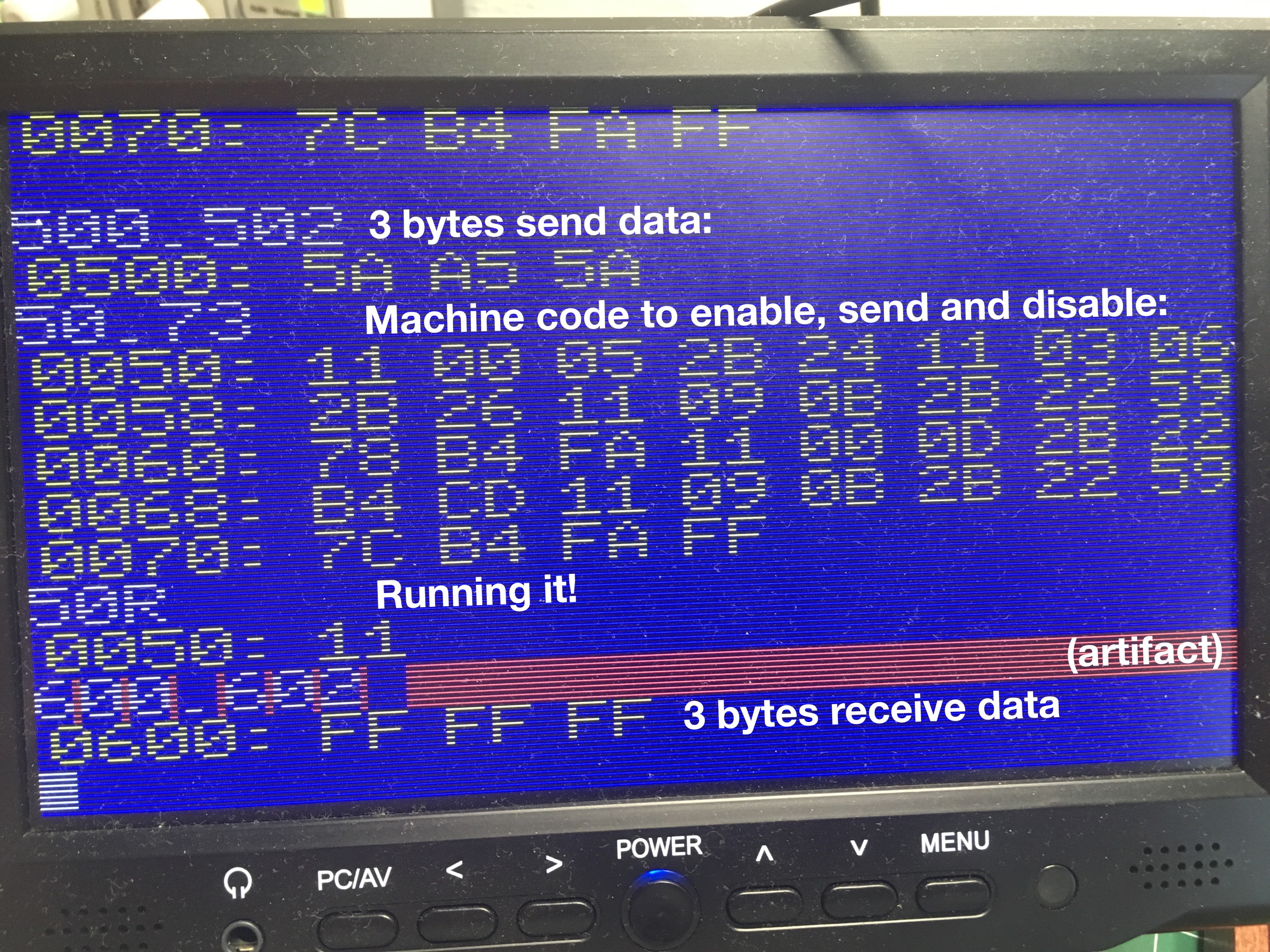
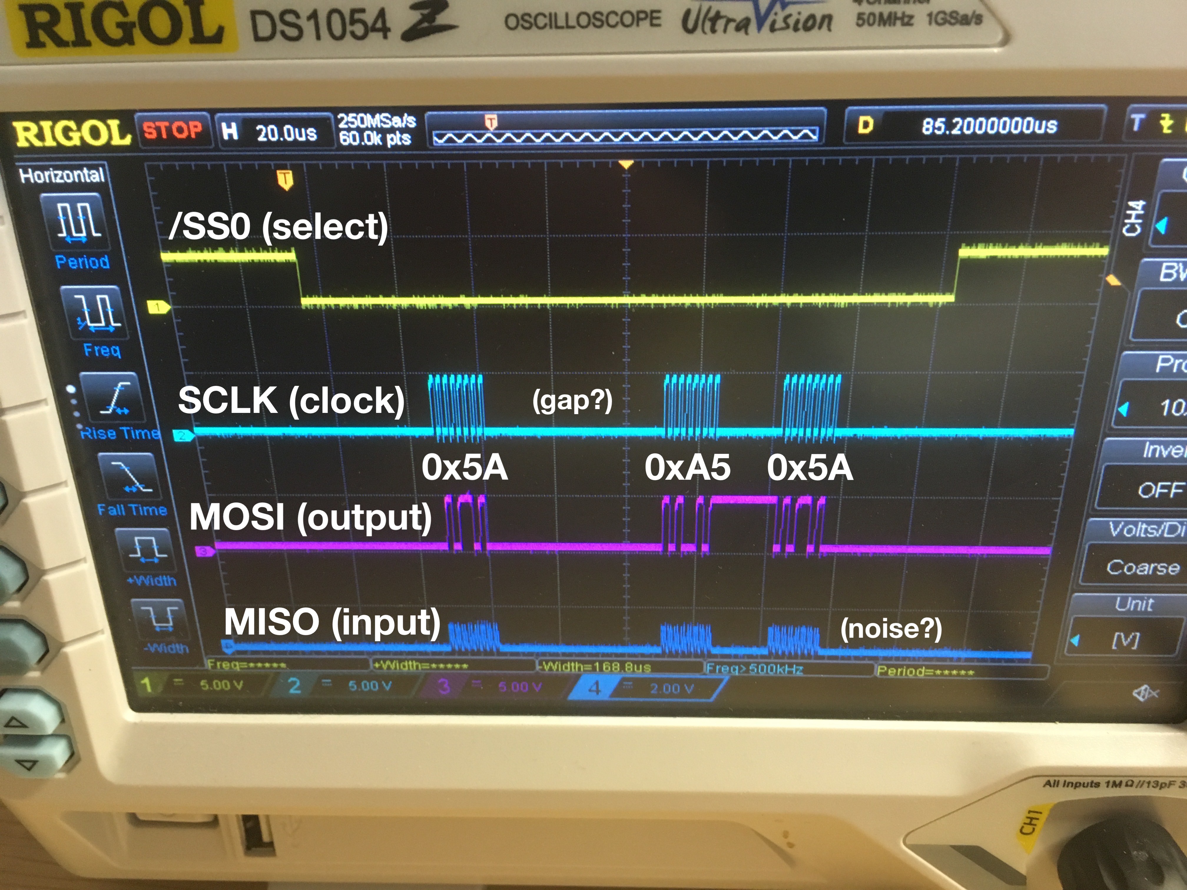
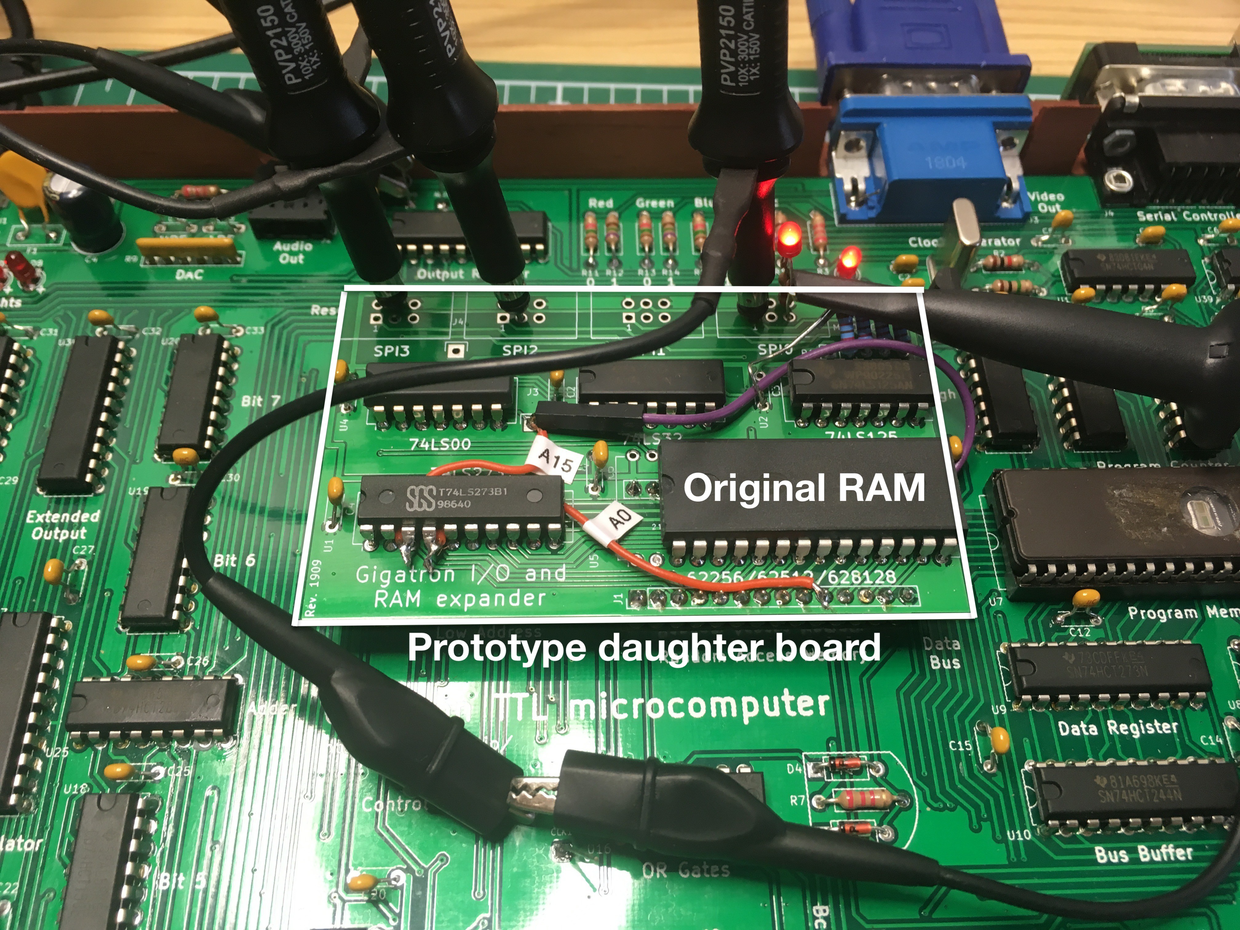
03/09/2019 at 13:34 • 0 commentsThe board is now integrated. Regular pin headers won't fit in the machined RAM socket: a square peg doesn't fit a round hole, literally. You need machine pin headers. Luckily the local electronics shop had a couple. After fixing a cycle counting bug in the driver code, I decided on using the WozMon for testing the board. With an LED I could easily determine that I can drive the enable lines of each SPI port. The next step is to send data. Here is what it looks like:
![]()
It looks promising on the scope. We are sending out the expected data while the Gigatron maintains its video signal. The longer gap is caused by a VGA pixel burst, during which the application is stalled. However, the input comes in as all-ones where we expect all-zeroes. The input lines looks noisy as well. As if the pull-down resistors don't do anything. [Edit: And that was exactly the case: bending over the resistors had broken off some of them.]
![]()
To be continued...
![]()
-
Will it work?
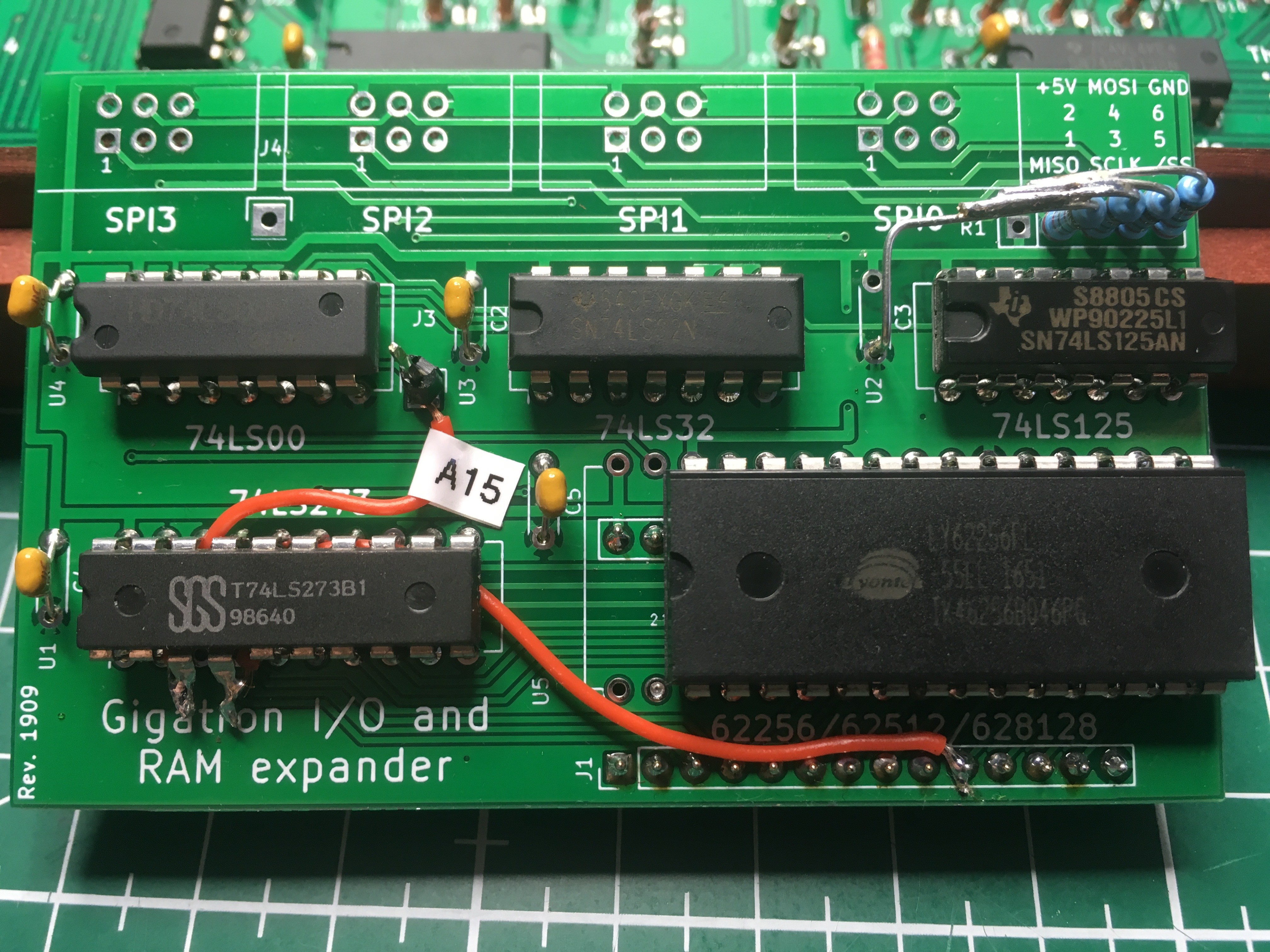
03/08/2019 at 16:08 • 0 commentsWhile waiting for the prototype board, it became clear that some small changes are desirable for much easier programming. Today the board came in and it's already obsoleted. To test our ideas, we add two patch wires and change the resistors from pull-up to pull-down. The pins for banking will also change, but I didn't bother to patch those as I put in the original 32K chip anyway. Nothing is socketed, so it fits inside the existing enclosure. Will it work?
![]()
Gigatron I/O and RAM expander
Adding four SPI ports and up to 128K of banked RAM using nothing more than 4 TTL chips and some wizardry.
 Marcel van Kervinck
 But I don't feel like porting FAT support from C either. Are we stuck?