Jack Flynn
-
When reality kicks your design in the nuts!
06/19/2019 at 08:22 • 0 commentsDesign to win
So online competitions there's a game to be played. A lot of the time a pretty mock up or design can do better than a more basic working model. Unfortunately when you try to make that pretty design in the real world the reality of manufacture and cost can really kick it in the nuts! With the LED Cubular the design was about meeting the criteria of lower cost but I also have very specific ascetics that I'm trying to achieve. Now that I'm trying to get the first prototypes made I'm finding the "low cost" aspect needs more focus and stock levels really do matter.
Low Stock - Design Change Required
The part - MMT-104-01-L-DH - is a small 2mm pitch 2 row 8 pin surface mount header that looks great in the design and fits in perfect but the stock level is a big fat "0". Like 0 everywhere, so that sucks. I'm going to have to adjust the design and use a more traditional 2.54mm pitch when then increases the overall footprint of the connector and may have further knock on effects. Damn.
High Cost? Kind of..
Looking at the cost factor for the bill of materials the MAX7219CWG+ is roughly £8 a piece and I need 6 per cube. Ouch. The annoying factor for me is that I looked online when making the decision and found a lot of cheap boards on ebay using the MAX7219 so I wrongly assumed it would be possible to pick it up cheaper. As always, getting into the higher quantities brings the cost down but that doesn't help me right now. I may need an alternative to this one...
-
#FR1Challenge - 2nd Place
06/05/2019 at 09:20 • 0 comments#FR1Challenge Results are In!
The FR1Challenge from circuit maker was the reason I actually found the motivation to start the LED Cubular Project. I figured if I could get myself into the top 10 I had a good chance of possibly getting some PCB vouchers to be able to produce a project. The LED Cubular has been sitting in the back of my mind as a pipe dream for about 5 years now. I never thought it would prove to be as popular as it is and I'm really thankful for all of the positive feedback I've had from the hackaday and circuitmaker community. Turns out, my design got me a 2nd place in the competition! Super chuffed.
So with the competition finally complete there's the ability to use the prize winnings to actually produce the LED Cubular. That's amazing! Watch this space, I'm on a roll now...
![]()
-
Pedestal Platform
06/04/2019 at 11:11 • 2 commentsPedestal Mock Up
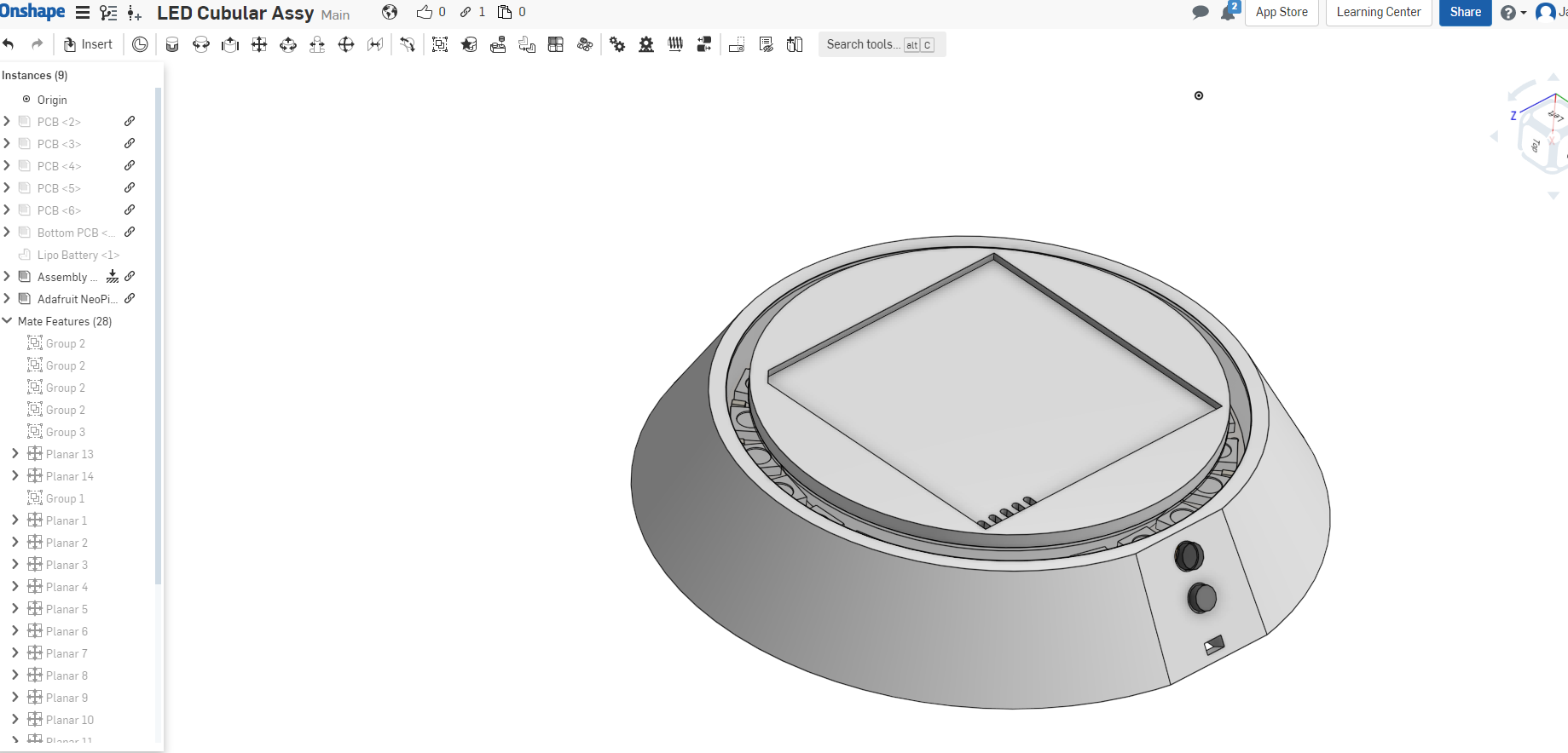
One of the key ideas of the LED Cubular is that once it's assembled it should be chargeable and re-programmable without disassembly. This is why on the bottom board it has a number of exposed pads to allow for this. The pads will touch on pogo pins on a "pedestal" platform that interfaces with the cube. I put together a general mock up of the pedestal and I like the idea of including a neopixel-24 ring within it to give a nice RGB glow around the cube. The cut corner on the cube ensures we get the orientation correct once it's placed on the pedestal. The pedestal will require it's own microcontroller to ensure power is applied only when there's a good connection and should add a level of safety that prevents any damage, kind of like a mac book handshake when plugging in power. This built in microcontroller will also allow reprogramming the cube and manage the neopixel ring as well as some button inputs which may be used to change the active "mode" the cube is in or some other functions.
Some mock up images of where my thoughts are at
![]()
![]()
![]()
![]()
![]()
Anyone got a 3d printer to spare? :D
-
Power Considerations
03/29/2019 at 16:25 • 0 commentsPower Requirements and Battery Selection
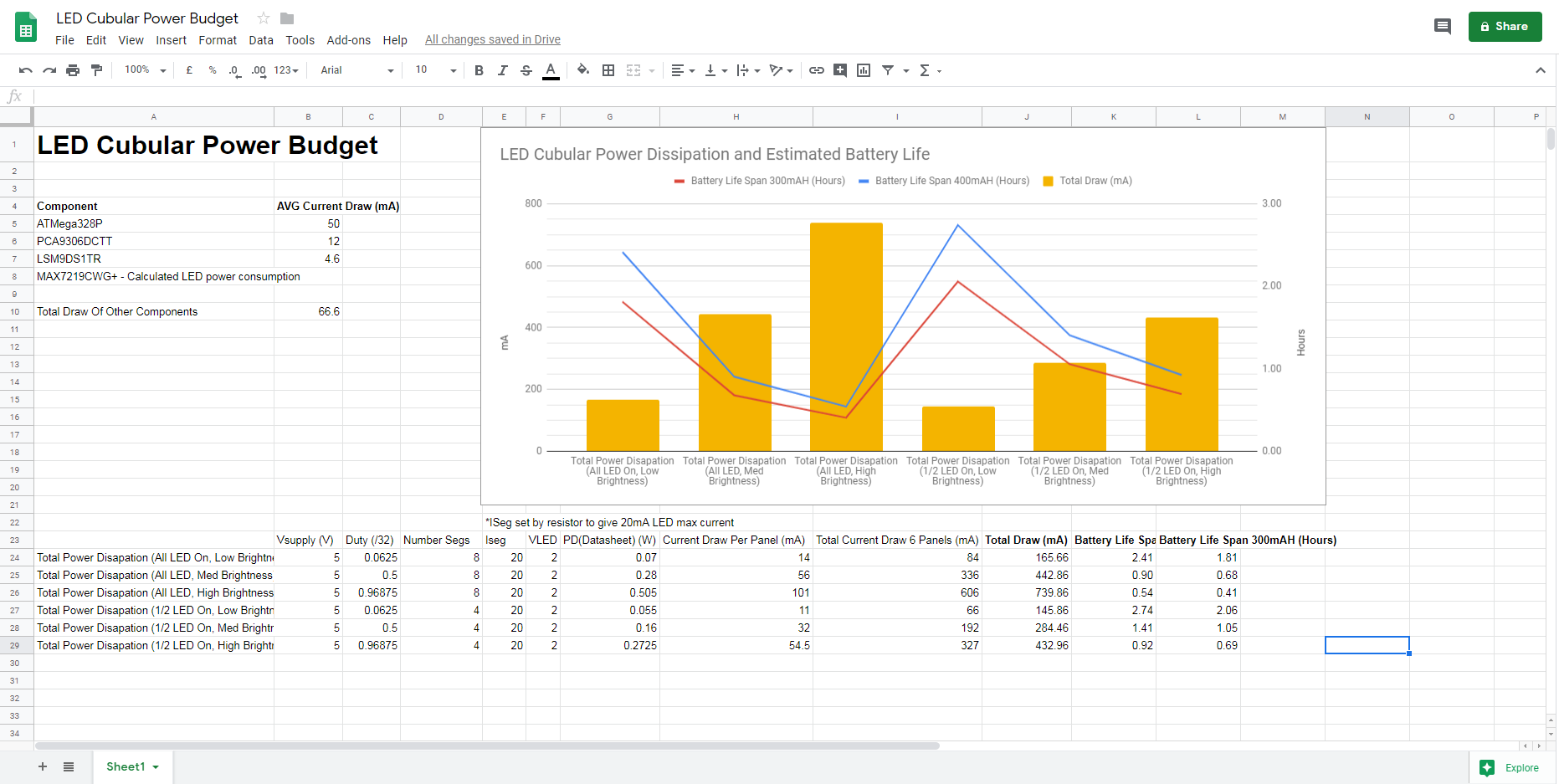
In order to select a suitable battery, I needed to first estimate the overall power consumption of the LED Cubular. I started by going over the datasheet for the main active components and the Max7219 had a great section about estimating the current draw based on number of LEDs active and other factors. I combined this with my other estimations to give a rough total current draw and added an additional 10% for possible other loses; such as regulator efficiency. You can check out the results here;
![]()
As you can see the tested values are for Brightness; Low, Medium, High and then ALL LEDs on and Half LEDs on. This gives us a peak value of ~750mA max draw when all of the LEDS are on (unlikely in normal usage) and at full brightness which I would expect to be rather blinding. I can prevent this situation in code by either maintaining a much lower max brightness or only allowing a max number of LEDs turned on at one time. Either way it gives us a rough estimate of what load a battery might be under.
I found 2 possible battery choices at 400mAH and 300mAH that would physically fit inside the cube. I estimated the liftime of the cube based on the capacity and draw for each battery which shows we should get at least half an hour with all of the LEDs on at a medium-high brightness. Which is well within my hopes and should give far more time under more animated lighting patterns.
Battery Selection
As mentioned, I found a 300mAH battery and there are a tonne of 400mAH drone batteries available but all of questionable specifications due to buying from ebay/amazon. The drone batteries would also require changing out the connector on either the board or the battery due to not using a standard JST connector. For now I'm considering this 400mAH Battery with dimensions of 26.5mm x 36.9mm x 5mm. Which you can see below will fit into the cube with a tight squeeze of space;
![]()
The major problem I haven't solved is how do I secure the battery down? I was hoping there might be some kind of "cable tie smd mount" that would allow me to cable tie the battery in place. I found these SMT cable clips which can be used to hold down wiring so I thought I could maybe do something like this;
![]()
Which would allow me to get 2 cable ties looped around the battery. Does anyone have a better idea?
-
Design Work Arounds - PCB Changes
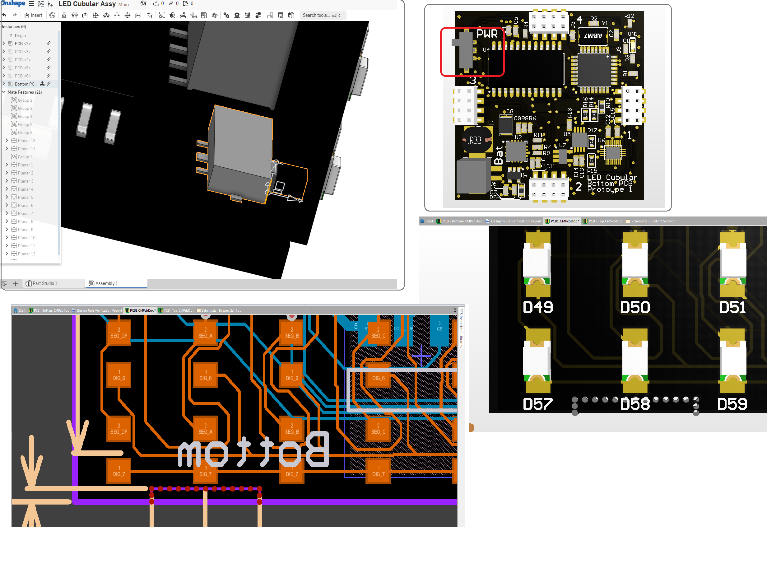
03/26/2019 at 17:03 • 0 commentsBlack PCB Mock Up and some issues
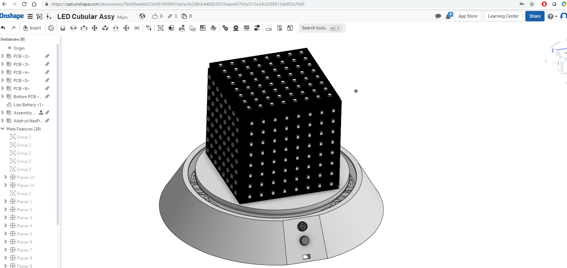
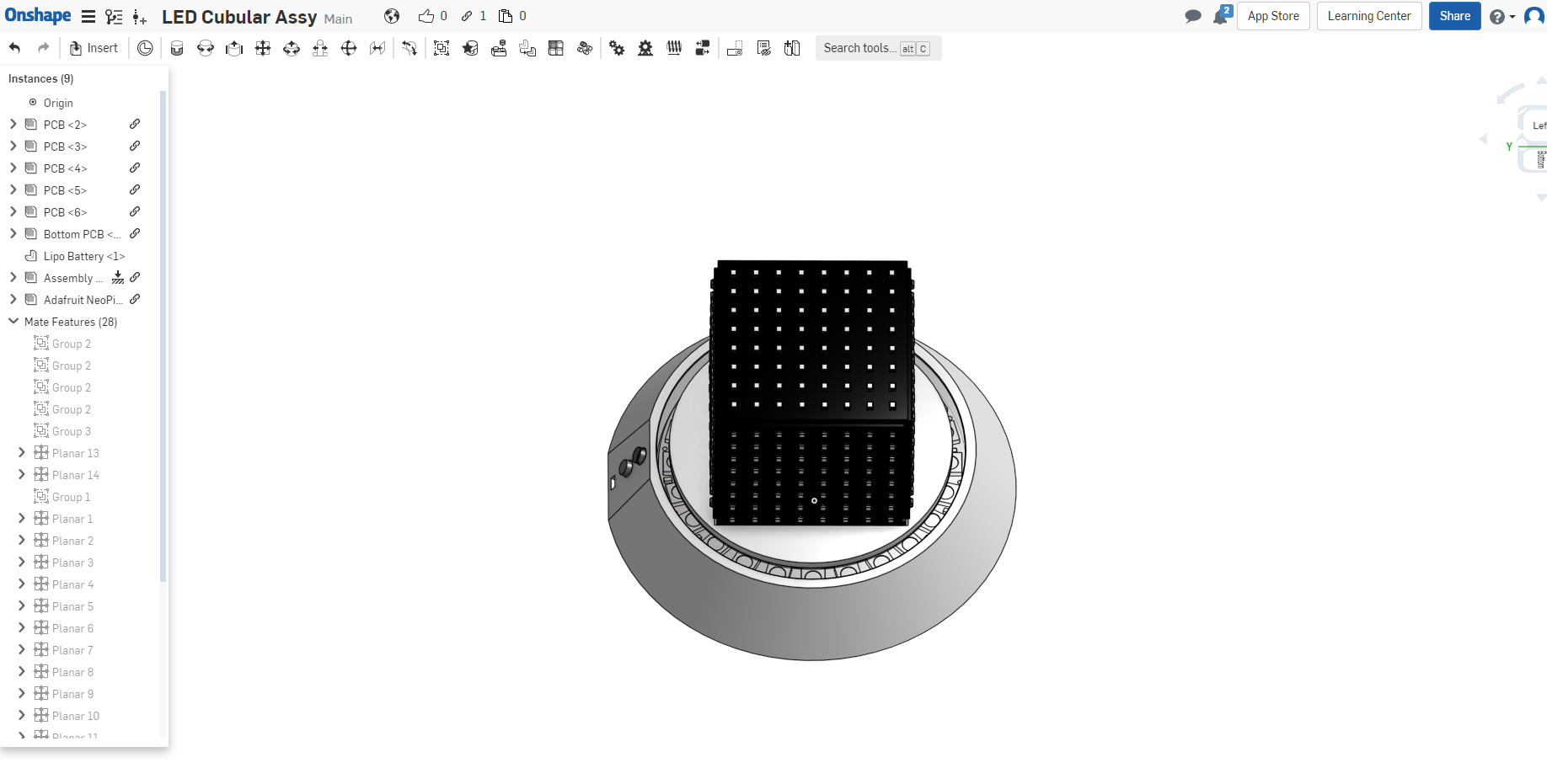
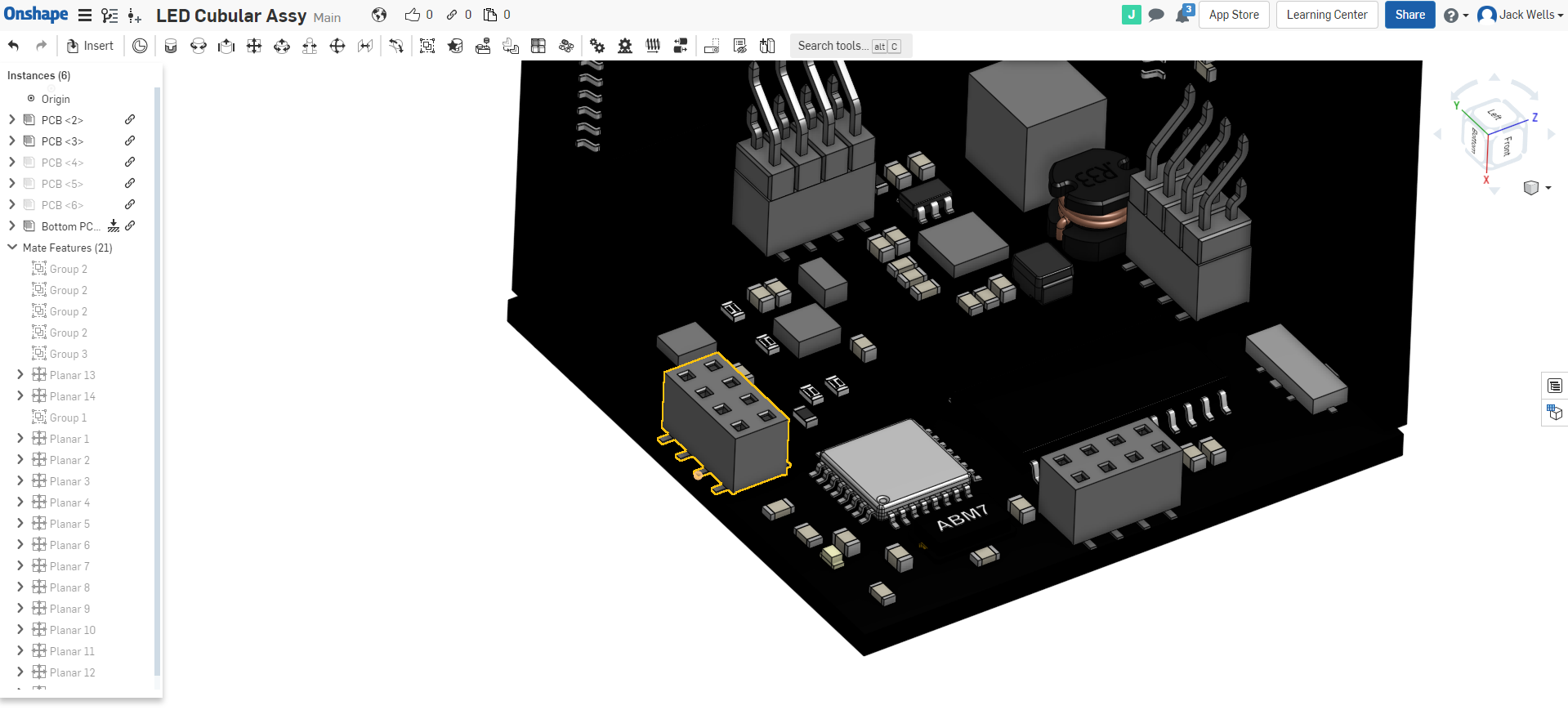
I like to visualise a a project with the big picture. I threw together the PCB steps files into "OnShape" which is a freebie 3d CAD package that also does assemblies. Viewing the cube as a "whole" allows me to check the physicality of the design and it's highlighted a few problems.
![]()
You can check out some 3d views of the LED Cubular in the vid below;
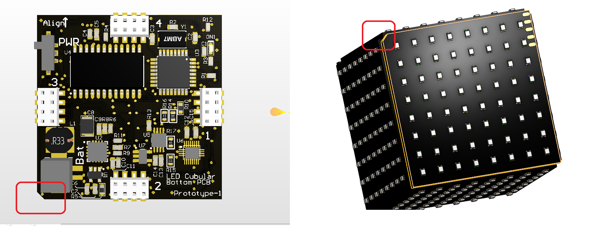
Highlighted Issue 1; Power Switch
In order to shut down the battery powered LED Cubular I wanted to have a small slide switch for on/off. This allows for switching state without having to take the top panel off. However, it means I need a hole in the cube so that I can flick the switch. I don't want to have lots of cut outs on every board so I've decided to add a break-off tab on each of the side panels. That way the one that is placed next to the power switch can be broken off to reveal the switch and the rest can still be relatively solid.
![]()
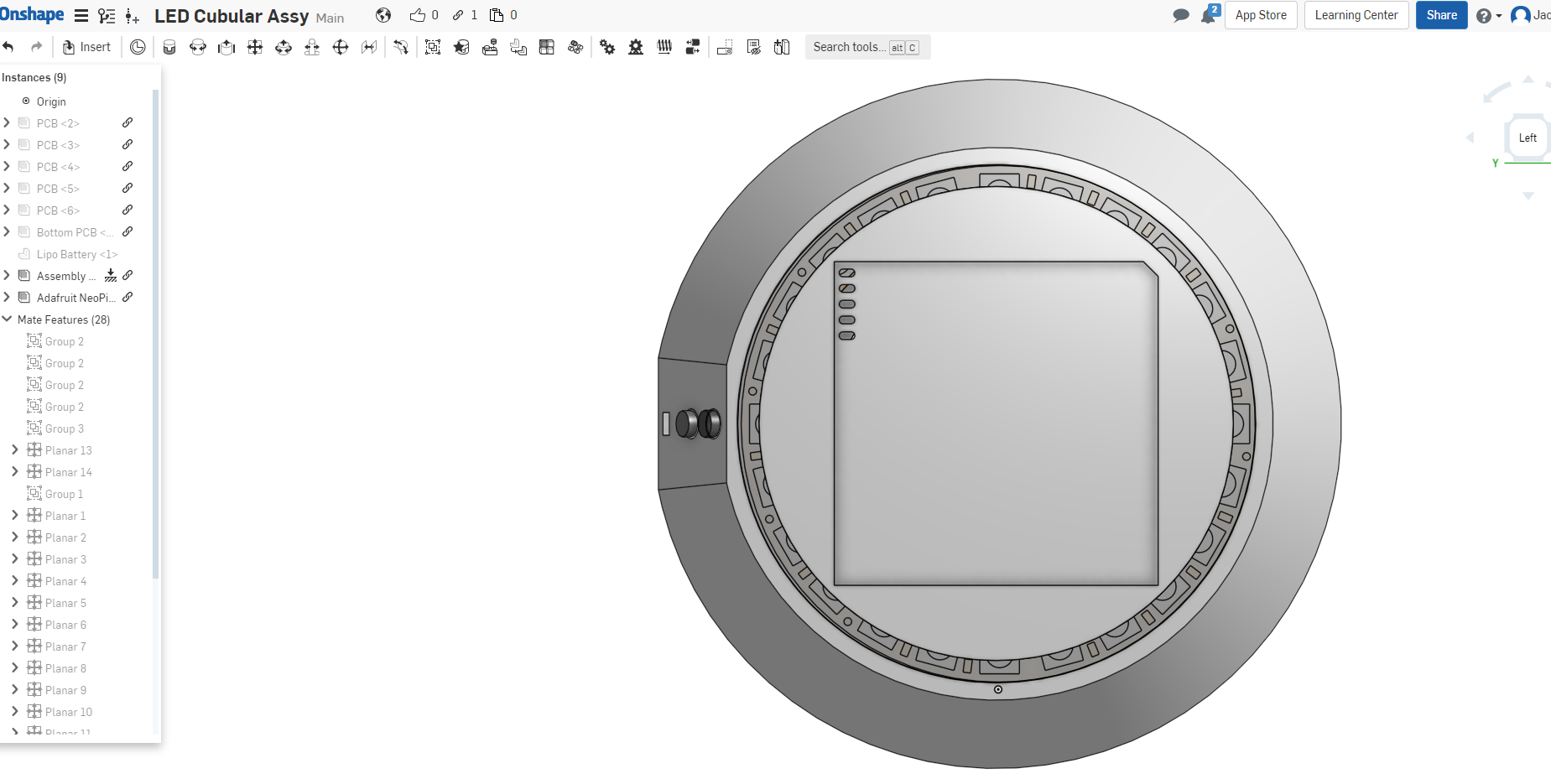
Highlighted Issue 2; Pad Alignment for Charging
One of the further development pieces is to create a "pedestal" for the cube to sit on. This pedestal will provide charging power as well as allow for easy reprogramming of the Arduino within the cube. However, one of my concerns is that it will be difficult to place the cube on the pedestal and get to pads and pins to line up. To help this, I've removed a "keying" corner on the cube. By designing the pedestal with a matching key, it should allow me to ensure that there's a specific orientation of the cube that sits nicely on the pedestal without the risk of misalignment.
![]()
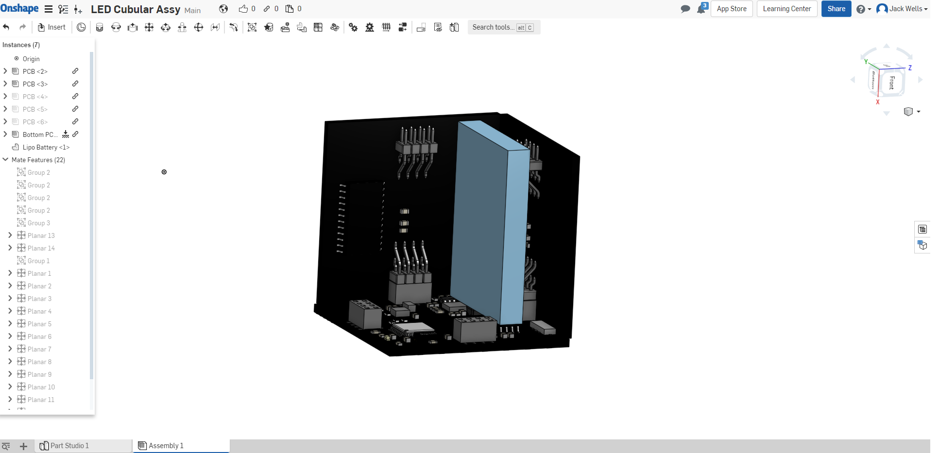
Highlighted Issue 3; Connector legs
So final issue I've spotted and was kind of aware of during the design process is that the legs for the connectors on the bottom and top PCBs will be protruding into the area where I want the side panels to be to create a closed cube. Common sense says that in the real world the Side panel PCBs will end up sitting on the legs and that ruins my closed cube ascetic;
![]()
You can see in the image that the legs of the connector are right up the board edge which is where the side panels should be flush. In order to overcome this I'll need to plot out small cuts in the side panel design that gives clearance to each of the pin legs on the bottom and top PCB. Totally doable, just takes a bit of thinking ahead.
-
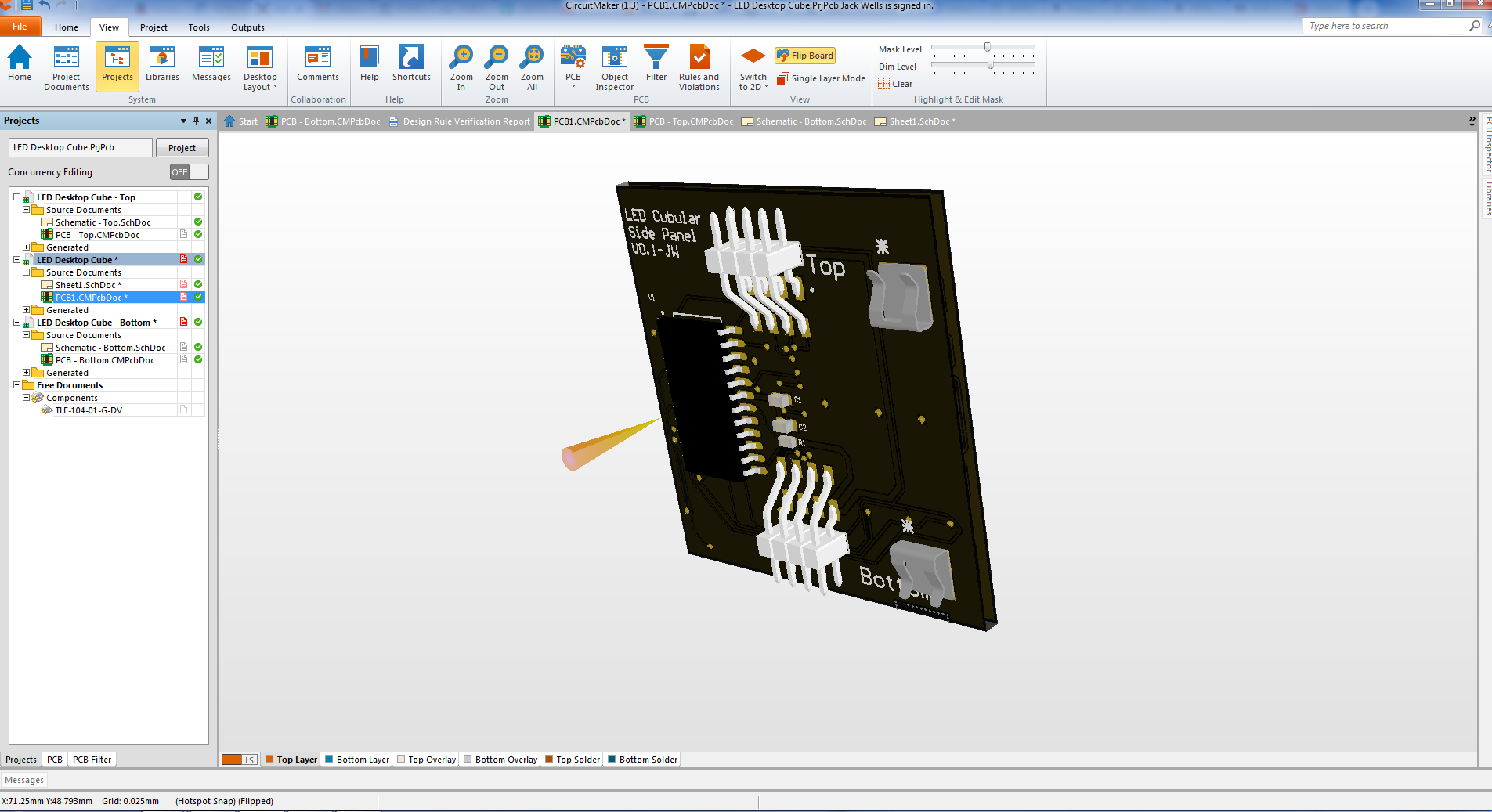
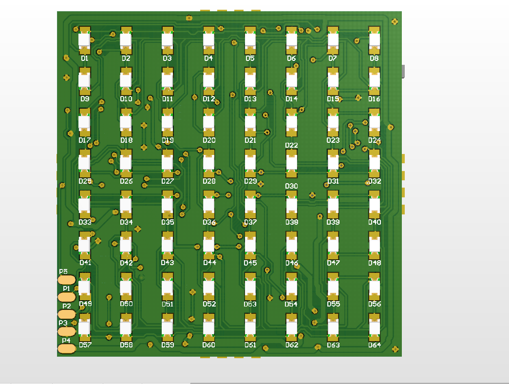
PCB Layout - Side Panel - 64 LED Matrix
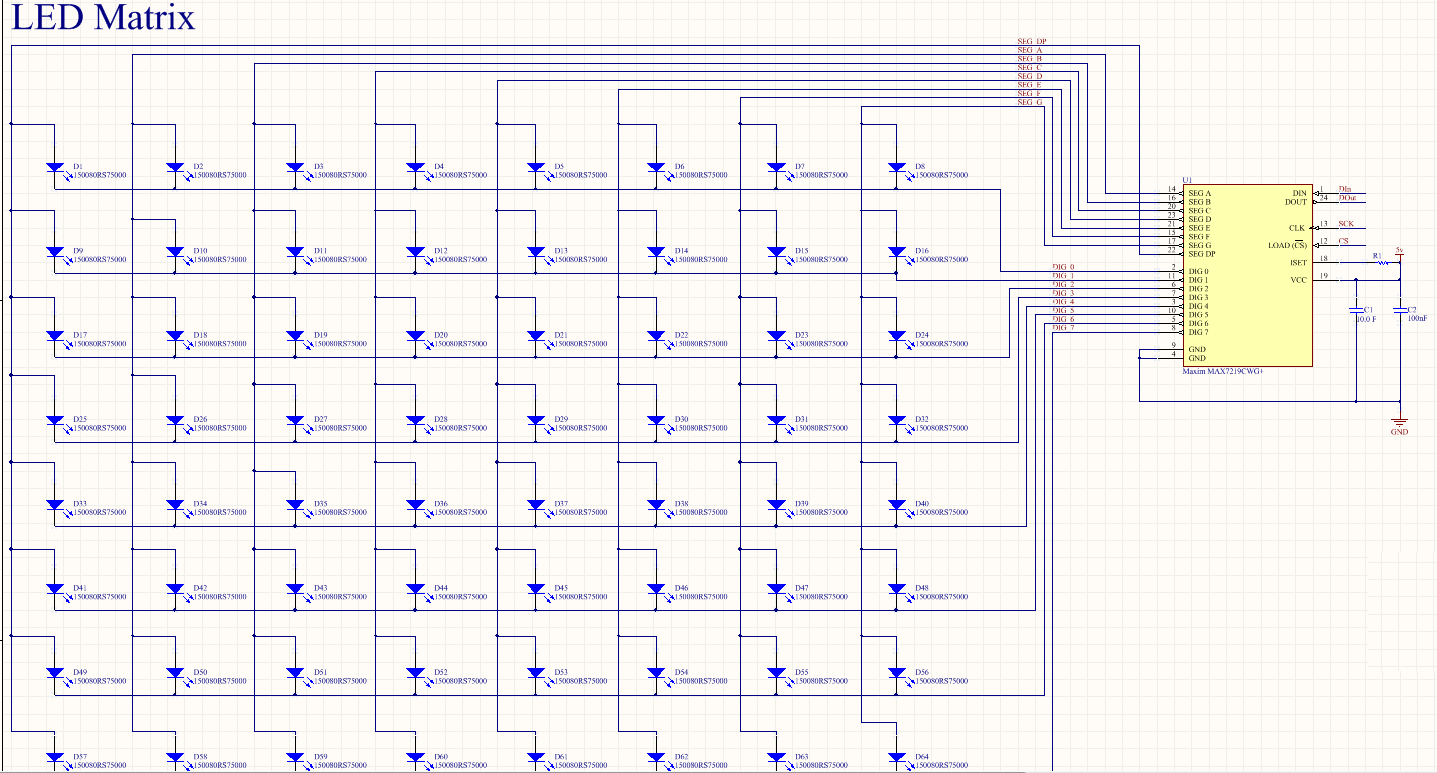
03/07/2019 at 10:39 • 0 commentsI put together a short video of my pcb track layout for the 64 front LEDs on the side panel. I'm no video editor but I think it comes across well. As can be seen from the schematic, the LEDs are connected to the Max7219 in a matrix layout.
![]()
This daisy chains the LEDs together in columns and rows which initially makes it difficult on a 2 layer design to not end up getting your wires crossed and losing a tonne of space on the bottom layer. I came up with a way of interconnecting the columns and rows (8x8) by passing the 6 mil traces under the LEDs. I could fit 2 lines under each LED while maintaining a 6mil clearance. Something I note that the Bantam Tools CNC mill should be able to achieve. Check out the video to see how I pulled it off;
-
Concept - General Design Discussions
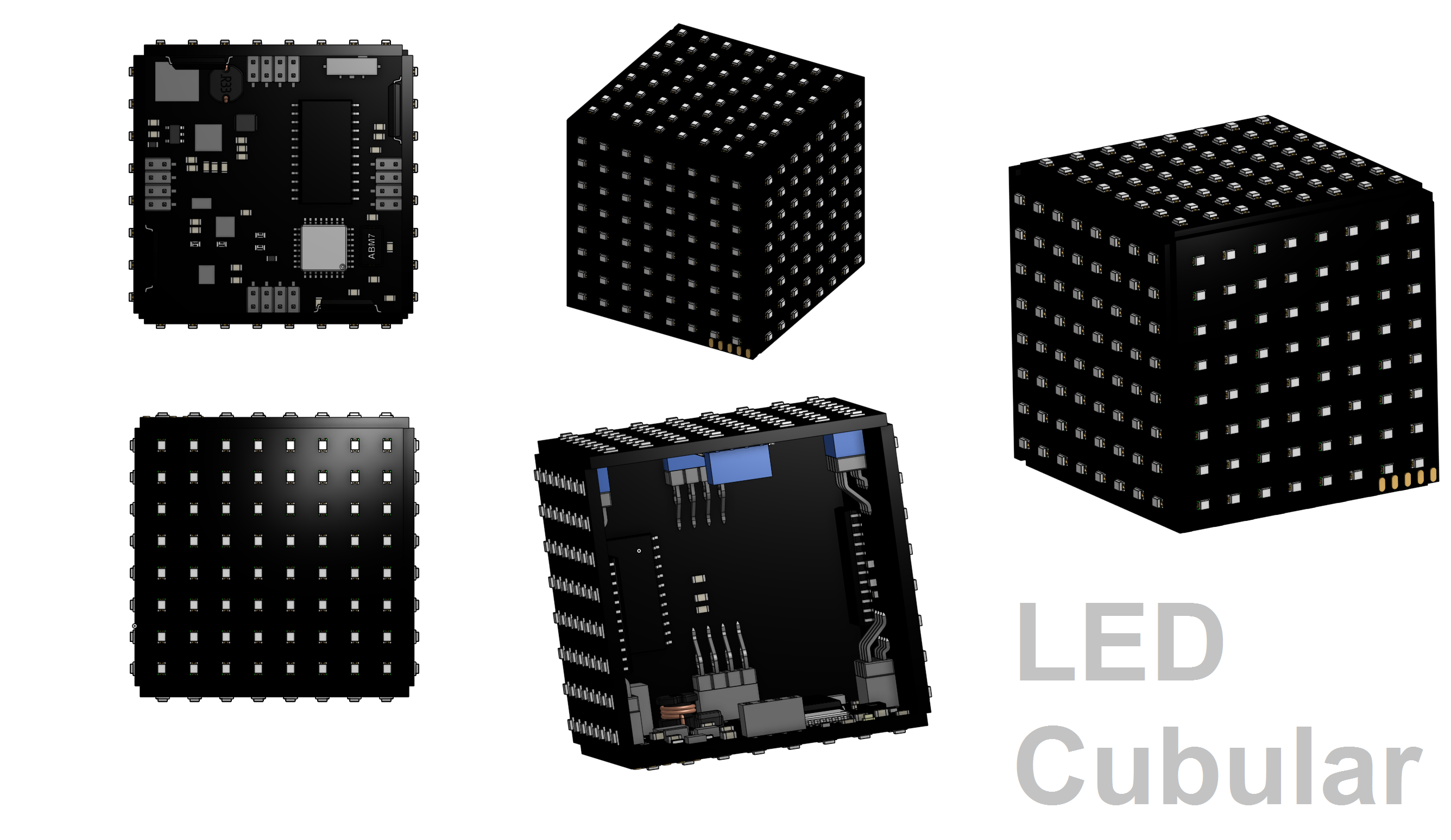
03/05/2019 at 18:42 • 1 commentDesign Style
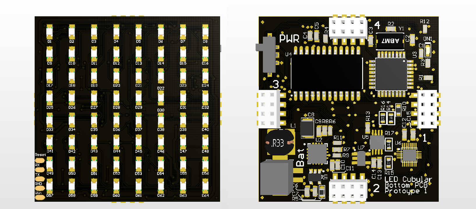
My vision for this design is to have the final boards produced with a black PCB and to remove the silk screen from the top overlay. I think this should give the cube a really modern and clean look while really allowing the LEDs to shine.
![]()
My latest changes to the bottom PCB are purely for visual. I've tried to add clear text where possible to highlight the key input/outputs and for prototyping I've left the Top Overlay on so we can see the individual LED numbers and interface pads.
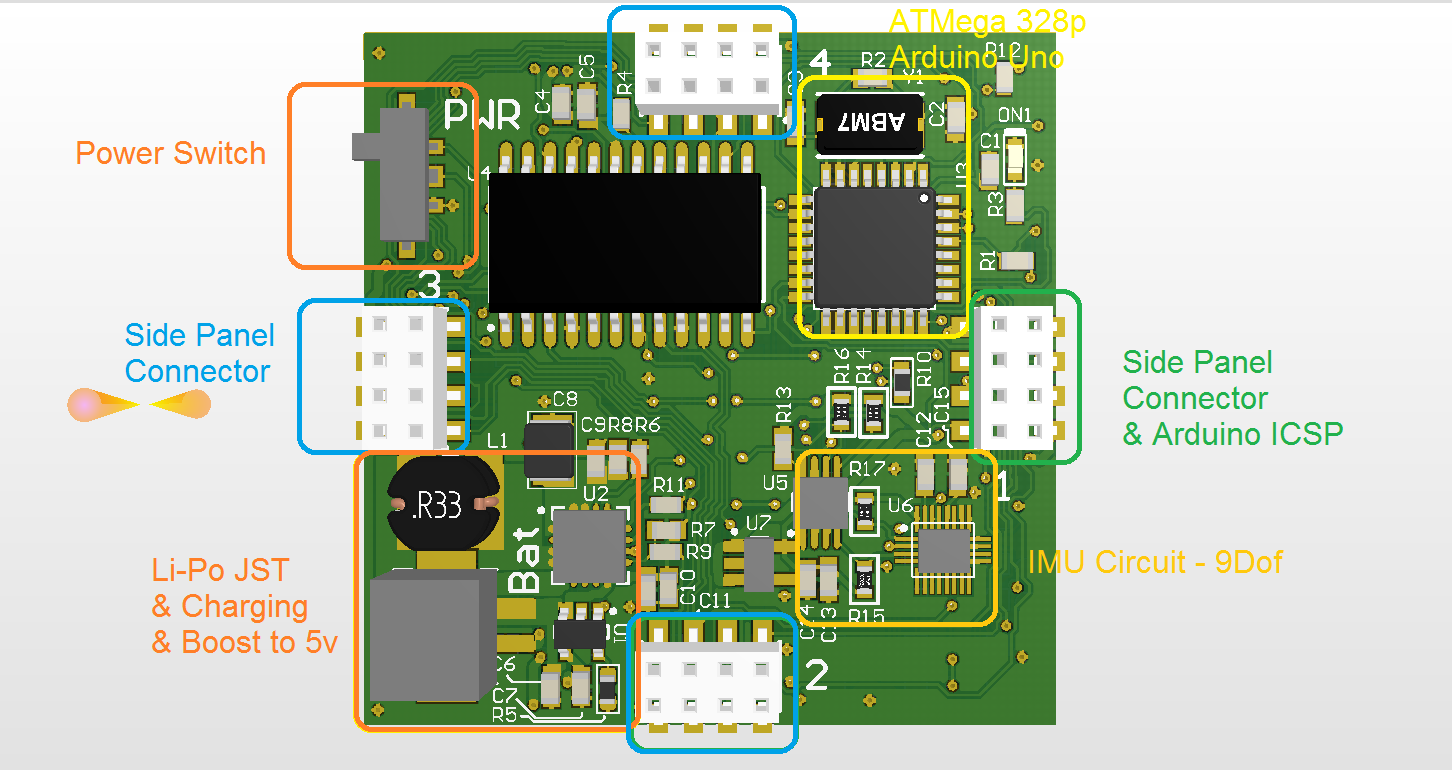
General Connections
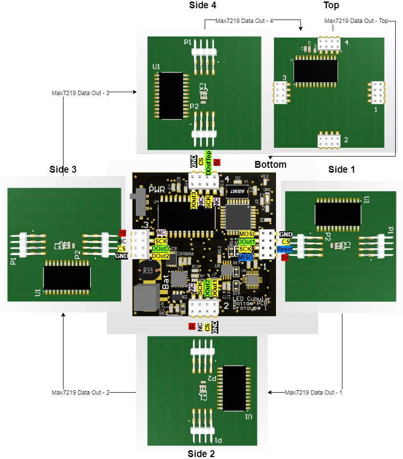
I've produced the following diagram in an effort to explain the general connection layout and functionality.
![]()
Each side panel and top panel have a max7219 for running the LEDs. These are daisy-chained through the bottom board as the data out of each max7219 is passed to the next board. Port 1 on the bottom panel can be used with an ICSP in order to burn the Arduino Bootloader to the ATMega328P as well as being used to drive the first side panel.
-
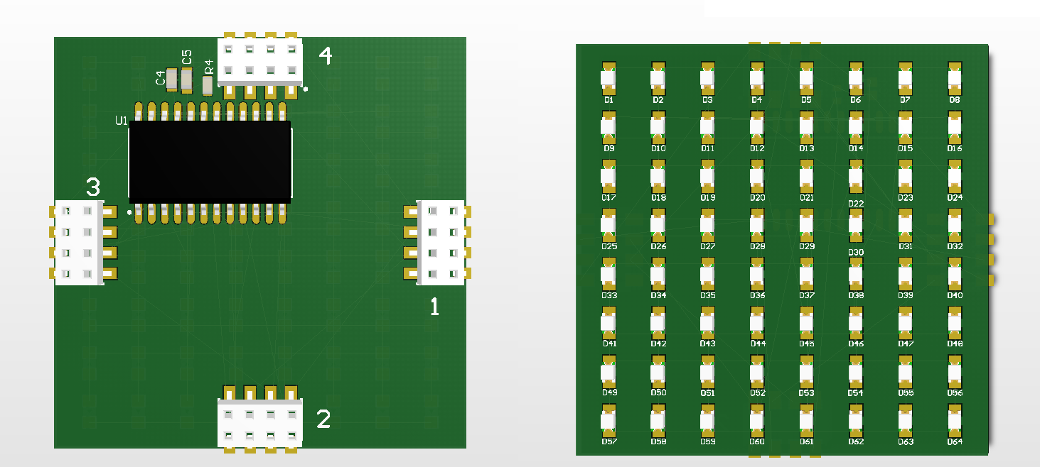
PCB Design - Side Panels & Top - Initial Design
03/04/2019 at 17:31 • 4 commentsSide Panels
![]()
The side panels for the LED Cubular are as simplistic as possible. Each one will have 64 LEDs on the front (no silk screen) and on the back is the connectors for the top and bottom and a max7219 which is a dedicated LED driver chip that can handle 64 LEDs in a matrix connection and communicates with the bottom PCB ATMega328P via a protocol similar to SPI. What's particularly nice is that the Max7219 can be daisy-chained together to allow for a single communication bus, requiring only 3 pins from the ATMega328P.
Top Panel
![]()
The top panel mirrors the connectors of the bottom but matches the side panels in simplicity. Perhaps in the future this extra space could be used for adding bluetooth functionality or other expanded features? For now, it's a simple mimic with the Max7219 and the 64 LEDs.
-
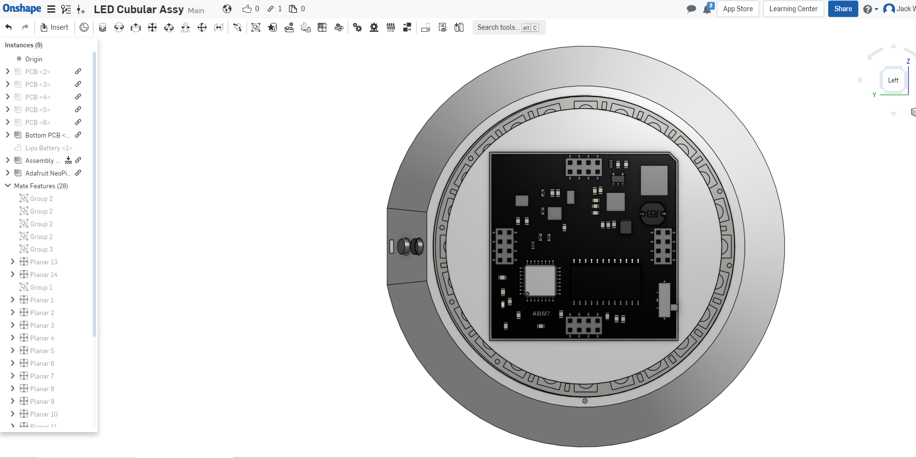
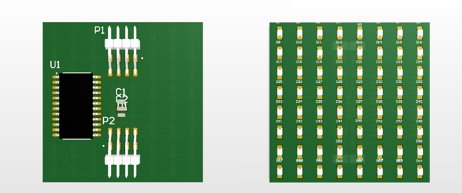
PCB Design - Bottom PCB - Initial Design
03/04/2019 at 16:24 • 2 comments![]()
For the initial design of the Bottom PCB I restricted myself to a 2 layer PCB. It's quick and dirty and really it should be a 4 layer so that I can offload power and ground to the internal layers. However, for an initial design and prototype I think it'll work. The Bottom PCB is the "Brains" of the project. It has the following features;
Arduino compatible ATMega328P
4 x Panel Connectors for the side panels - 1 of these can be used with an ICSP programmer to burn the Arduino Bootloader to the ATMega328P.
IMU - LSM9DS1TR - for orientation tracking i2c accelerometer, gyroscopes and magnetometer
LiPo JST Battery connector with charging chip and 5v Boost - based on Adafruit 500 Powerboost
Max 7219 LED Driver for 64 LEDs. Communication via an SPI-similar bus.
And on the back side we have the 64 SMD 0805 LEDs and exposed pads for pogo pins to allow for charging and reprogramming.
![]()
LED Cubular - LED Desktop Cube
Arduino based; 6 PCBs all with 64 LEDs on the outer face to form a li-po powered cube of 384 LED coolness!