 John Loeffler
-
1Hackaday Prize Q and A
i. Is this a unique solution to a particular challenge facing the world today?
Power Supply and Oscilloscopes are an Invaluable pieces of equipment for Engineers, Hobbyist, and Student. It allows them to test their circuits under a variety of voltage and current conditions. The problem is the are bulky, stationary, and expensive. With release of these cheap Battery power supplies that attach to the breadboards users can make their projects mobile.
The goal of Open Power is to take it a few steps further. To integrate Lithium Rechargeable batteries. Quick Disconnect and a Variable Rail (0.6V -12V). With Iterations capable of Constant Current, Current Monitoring, Digital I/O indicators, Voltage Reads, Crude Oscilloscope and Logic Analyzers.
All These features with an aim at keeping cost as low as possible. With our cheapest unit (Less than $2.50 Cost) multiple units can be Purchased and used in multiple projects. This solves the problem of having to disconnect the circuit from the power supply to start a new project.
Open Power will NOT replace the bench top power supply or oscilloscope, But it will supplement them and allow greater access to Students, Hobbyist and Makers.
![]()
---------------------------------------------------------------------------------------------------------------------------
ii. How thoroughly documented were the design process & design decisions?
The Design Considerations were based on many factors But it boils down to the 3 Basic Designs with improvement iterations.
---------------------------------------------------------------------------------------------------------------------------
![]()
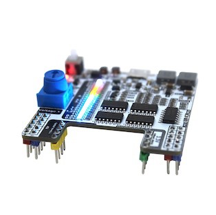
Prototype 1 A was designed to be the cheapest unit available. Focus is to provide users with a Usb Chargeable unit with 5 and 3.3v outputs as well as an adjustable rail (0.6V - 12V). Prototype 1A accomplished this with the brute force method and comprised of 133 Components. The Fabrication came back and was successfully tested. Ideas of improvement from the Hackaday community sparked a design iteration that would indicate the Voltage even when the device was powered off.(Status: Complete and tested)
---------------------------------------------------------------------------------------------------------------------------
![]()
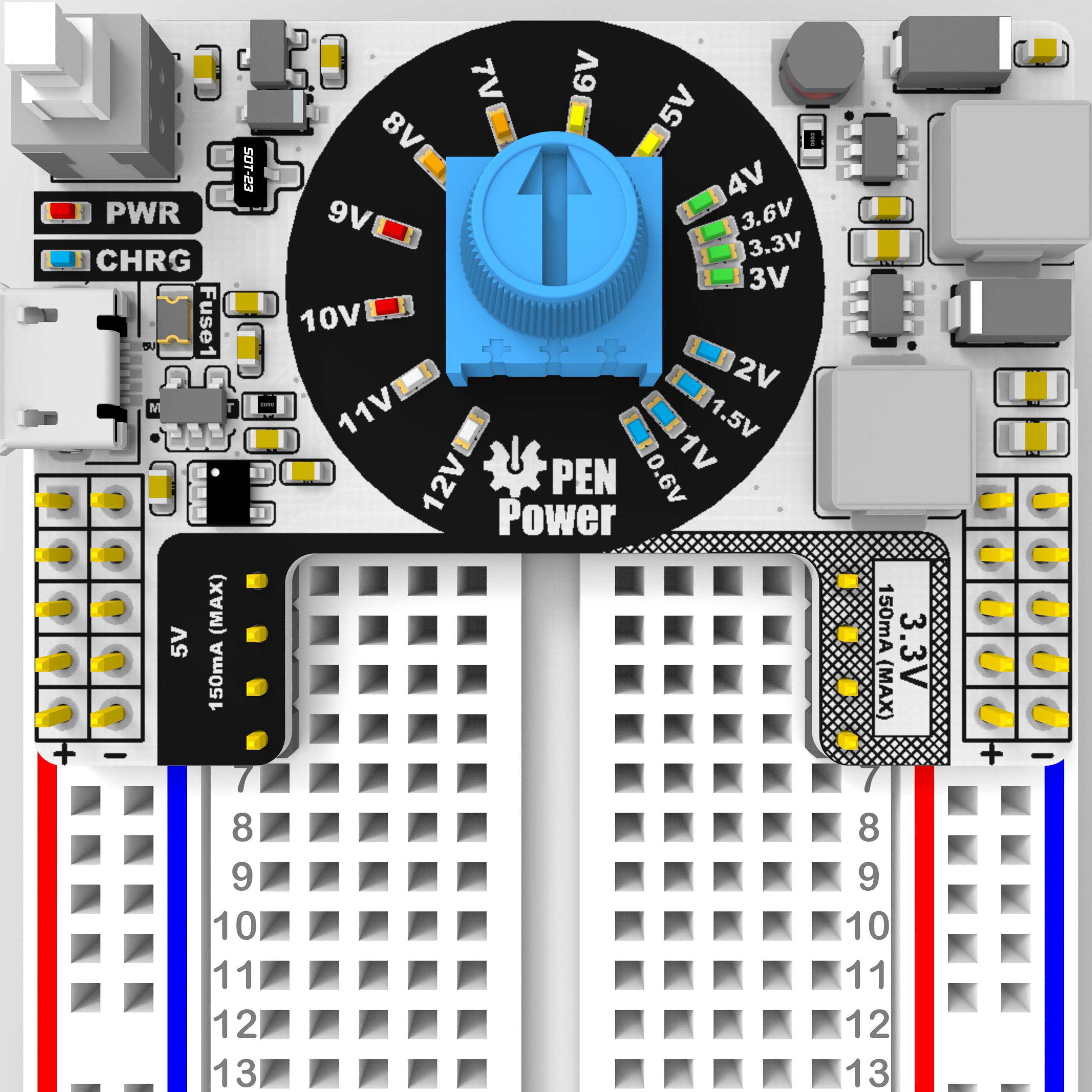
Prototype 1B took those considerations and moved the adjustment knob to the center and arranged the LEDs around the voltage control knob. This allows the user to see the set voltage even before it is turned on. This offers a problem that not all Potentiometers are accurate and may not line up with the LEDs. To solve this a potentiometer bridges the voltage knob to set its range. and the Lower feedback resistor will be used to set the 0.6V. In addition, most of the resistors were switched to resistor arrays which offer a tighter layout and easier reflow. The Boards height as also reduced from 50mm to 38mm, offering a more compact form Factor.
(Status: Complete and tested)
----------------------------------------------------------------------------------------------------------------------------
![]()
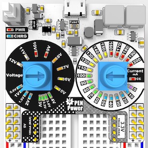
Prototype 1C took it one step further and integrated a constant current knob. This works by measuring the load current at the low end and toggling the feedback pin on and off if it exceeds the threshold. Set by the current knob. The LEDs surrounding the current knob work off sensing the current and using comparators to show the current in increments of 10mA.
(Status: Currently being Fabricated).
----------------------------------------------------------------------------------------------------------------------------
![]()
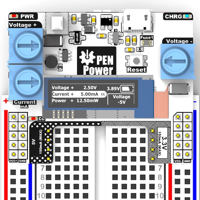
Prototype 2A was designed to integrate a negative rail for Op-amp usage. Since this is for a more advance engineer with more demanding and accurate requirements we decided to implement a OLED display to display the voltage. At the moment we have only done a layout and have not tested the negative rail. This circuit is to be entirely analog with the display only providing voltage and current feedback.
(Status: Layout Designed)
----------------------------------------------------------------------------------------------------------------------------
![]()
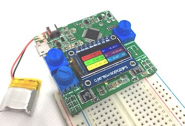
Prototype 3A was designed to be the most advanced and accurate. It uses a single IC to boost and invert to +-13V. This is then past through specialized LDO’s that can be adjusted down to 0V. This method is costly but provides the best performance of all the prototypes. Like all models the power is accomplished with complete analog and the Samd21 only does sensing and displays the data on the 0.96in Color TFT. The reason keeping it analog is stability. We do not want a code error compromising the output.
(Status: Complete and tested)
----------------------------------------------------------------------------------------------------------------------------
![]()
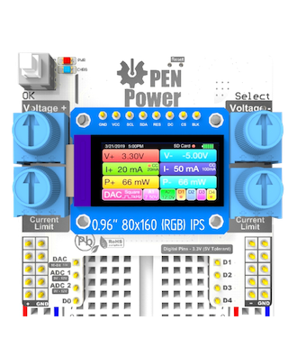
Prototype 3B Was designed to make the correction in 3A. In addition to the +-Rails are analog and digital inputs that can be utilized by the user. 2 Analog inputs and 4 Digital inputs. Analog output DAC can also be used to provide small signals for testing.
(Status: Currently being Fabricated)
----------------------------------------------------------------------------------------------------------------------------
![]()
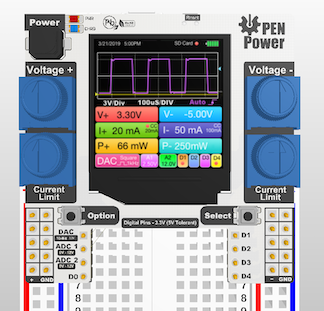
Prototype 3C is the moonshot. The Screen is upgraded to a 1.3” IPS to provide a larger viewing area. Because of the larger display a SAMD51 is used to keep a stable refresh rate. This additional area can be utilized for a Crude Oscilloscope and or Logic analyzer.
(Status: Layout Designed)
-----------------------------------------------------------------------------------------------------------------------------
iii. How ready is this design be taken to market?
Prototype 1A, 1B and 3A Have been Designed and are currently being tested. At the moment Additional safety features are being tested including short Circuit, Overload, etc. These will be read for market within the next month or so. These will require sourcing and testing to get the cost down as low as possible.
One of the biggest challenges with this will be sourcing parts and manufactures to keep the cost low. Currently the entry model uses 5x LM339 Comparators. Even in quantities of 5 is less than the cheapest MCU. But there is a point where there are enough led and comparators that a simple MCU and OLED Makes Sense. Prototype 2A will address this. Within a 2 month Development Prototype 1C, 2A and 3B will be Ready for market.
Prototype 3C will require additional Assistance as it will need special libraries for the 1.3” display to provide fast enough refresh rate for real time O-scope. This would require some Assembly level coding. But once the code is available to everyone improvements in performance can be made by the User base and implemented in future releases.
Working with Suppliers, PCB Fab and assembly labs will be a major focus of bringing OPEN Power to the Masses.
------------------------------------------------------------------------------------------------------------------------------
iv. How complete is the project?
The first few prototype are complete and work as intended. The rest of the iterations will require fabrication and testing before release to the market. With each Iteration design flaws and the User interface is refined for a more user friendly experience.
OPEN Power
I didn't have enough to buy a Lab Bench PSU... So I made one.

Discussions
Become a Hackaday.io Member
Create an account to leave a comment. Already have an account? Log In.