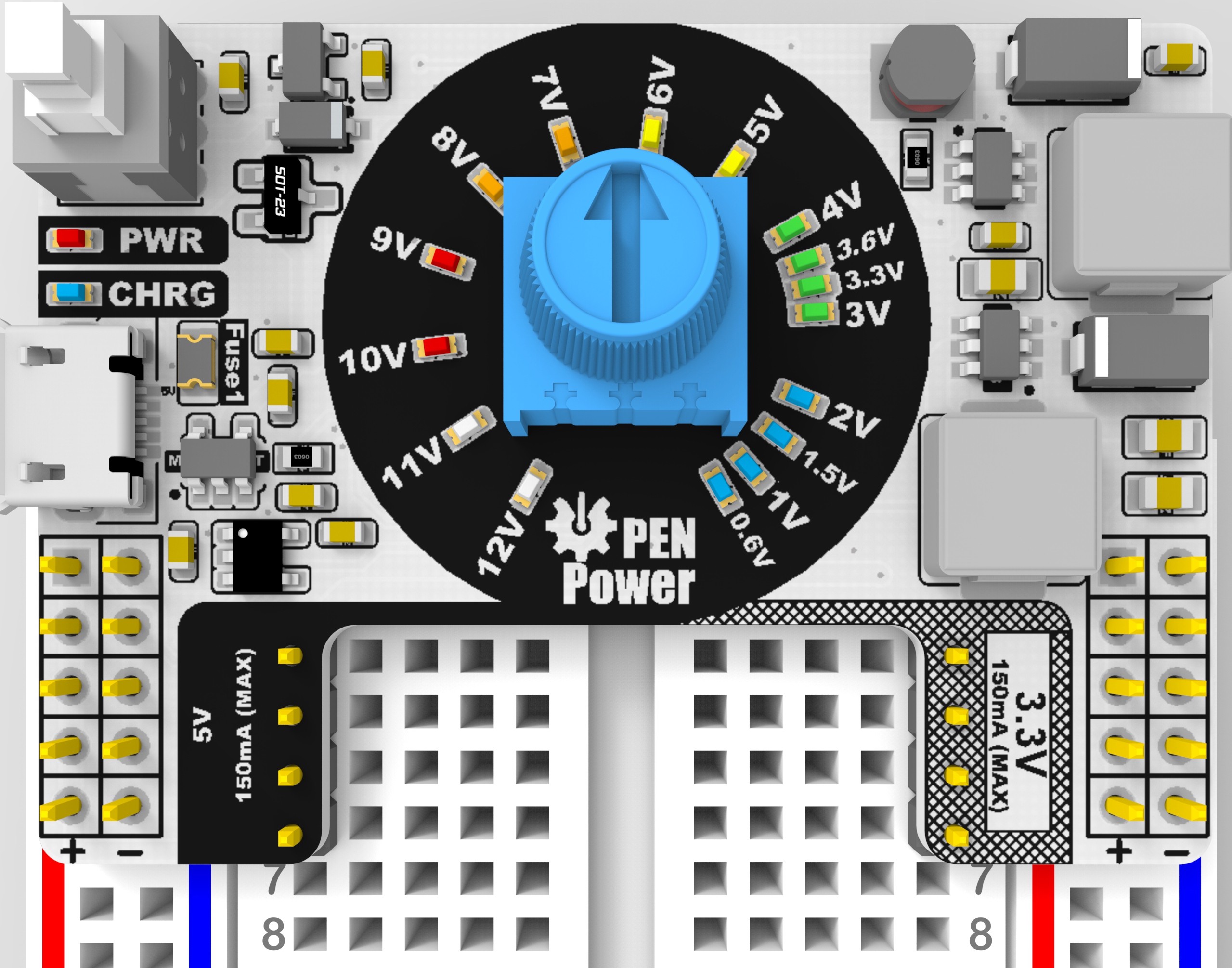
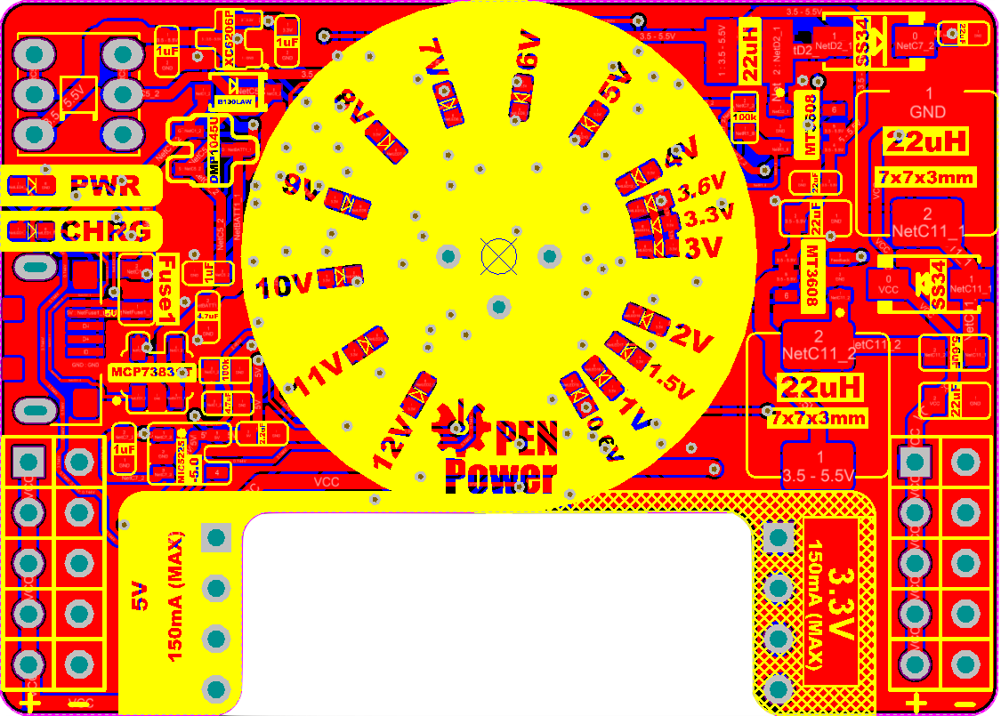
Received Prototype 1B Boards back from the fab. 1B is to test the range of the Potentiometer and the spacing of the leds. 1b Is not meant to be sold. It is a test for 1C with will integrate constant current and therefor the voltage may not be the same as the set voltage. Use Manufacture PCBway and was a little disappointed by the quality of the Silkscreen
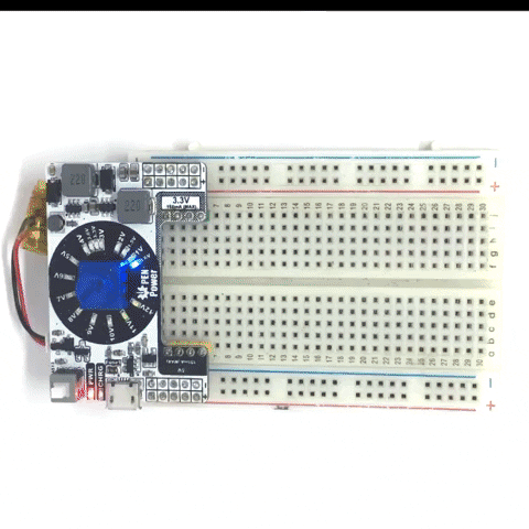
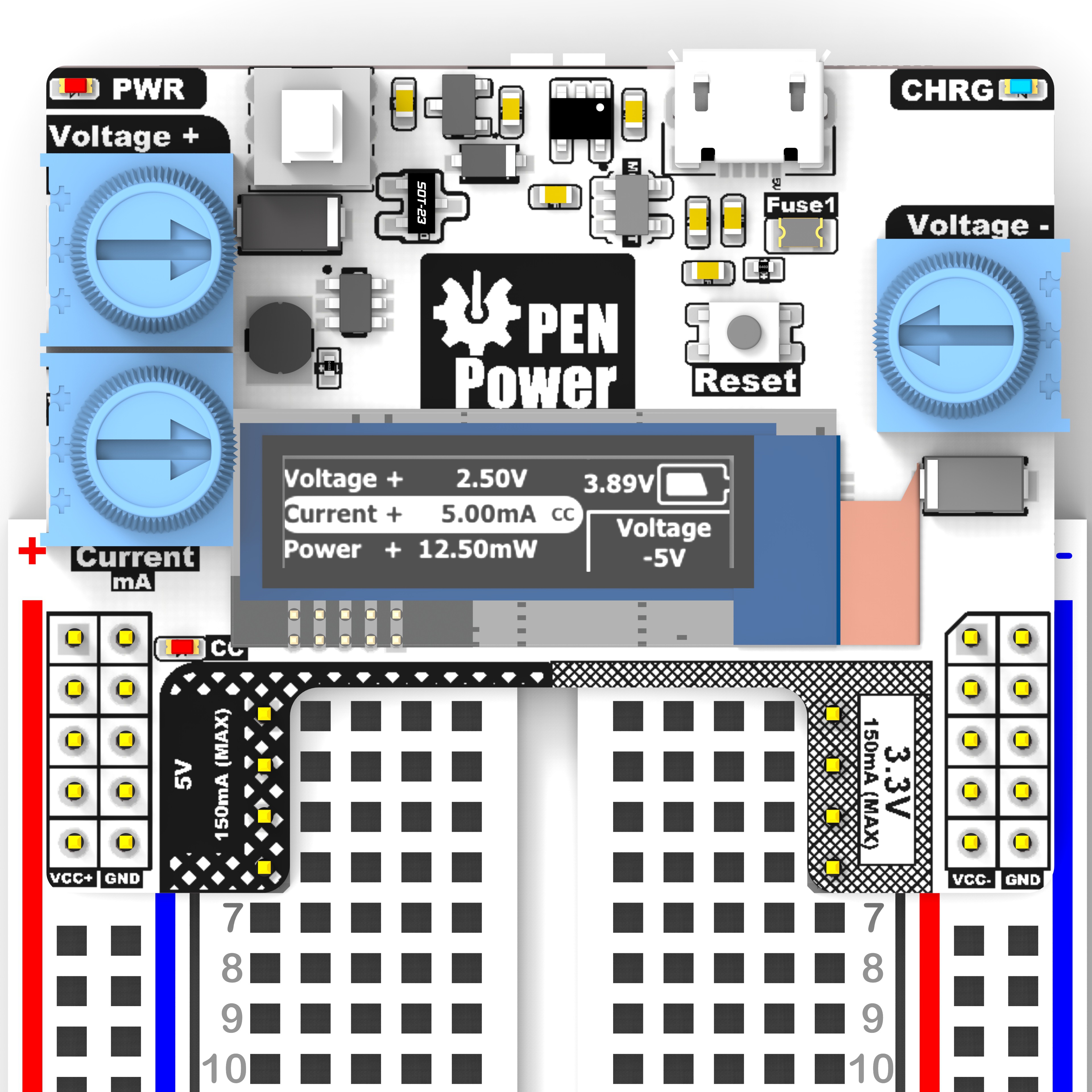
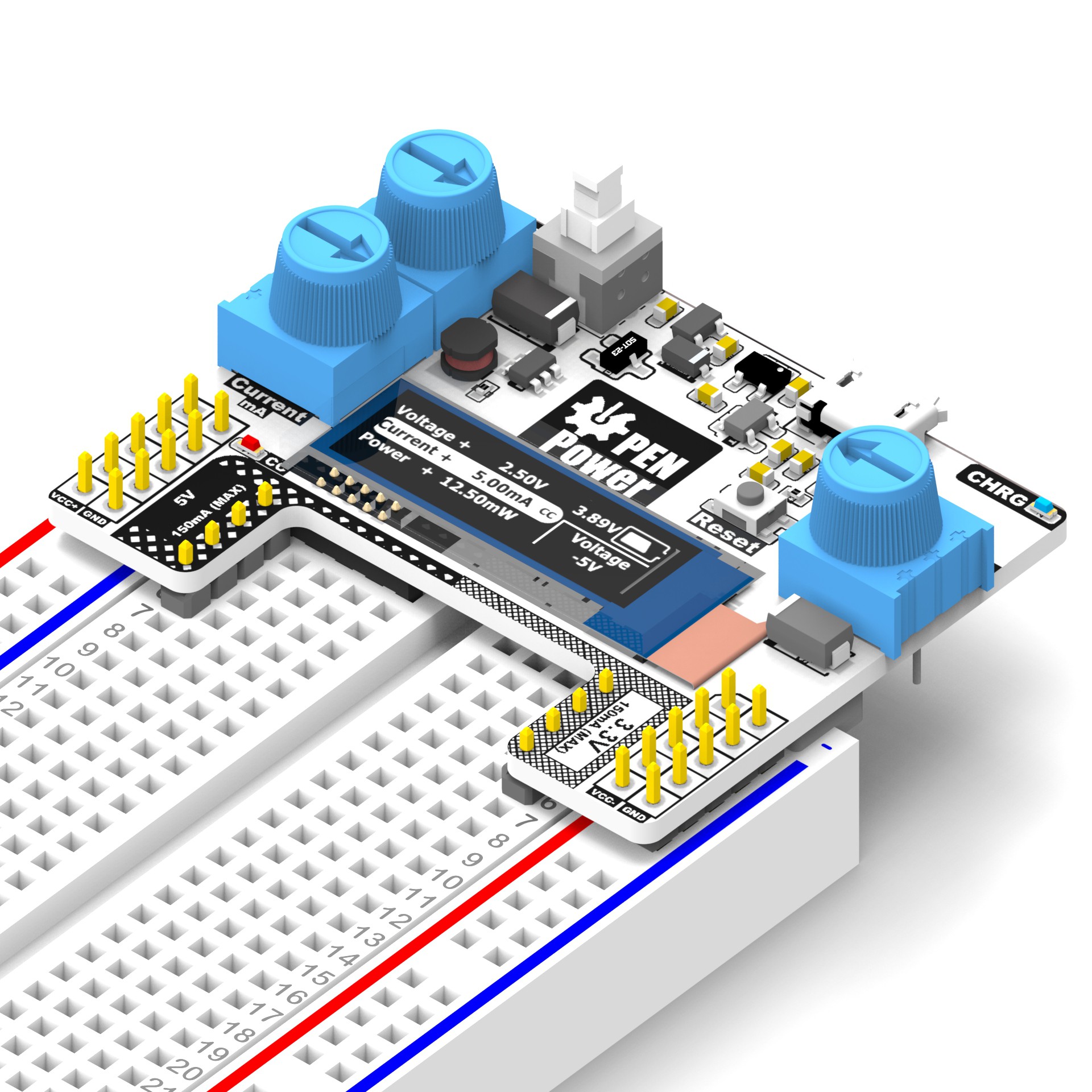
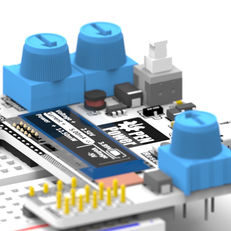
Prototype 2A implements an OLED upgrade allowing users a graphic feedback. In addition to reducing board size. The Right Rail was changed to be an adjustable negative rail and has its folding displayed on the OLED. Further iterations would include different size OLEDs.
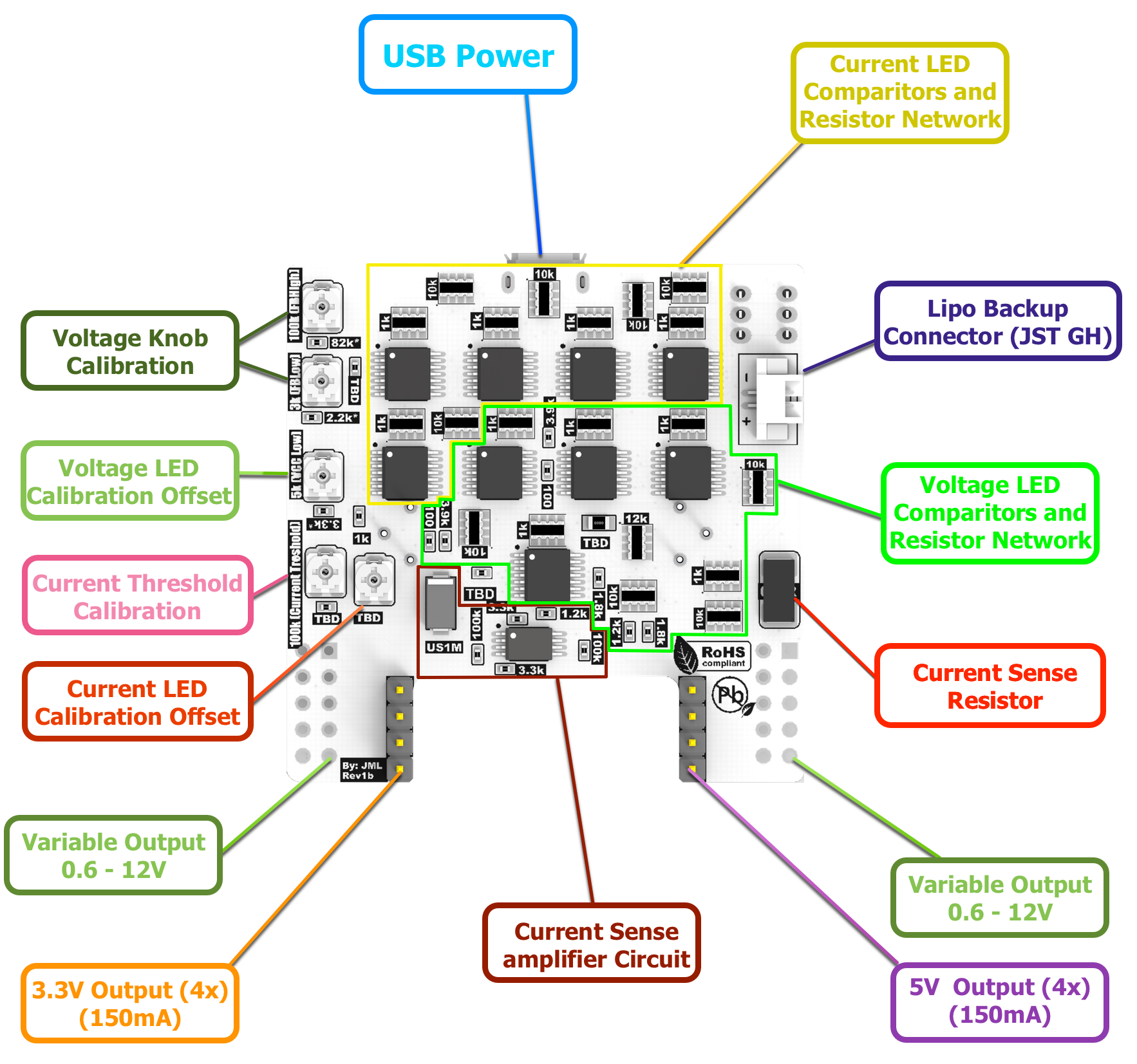
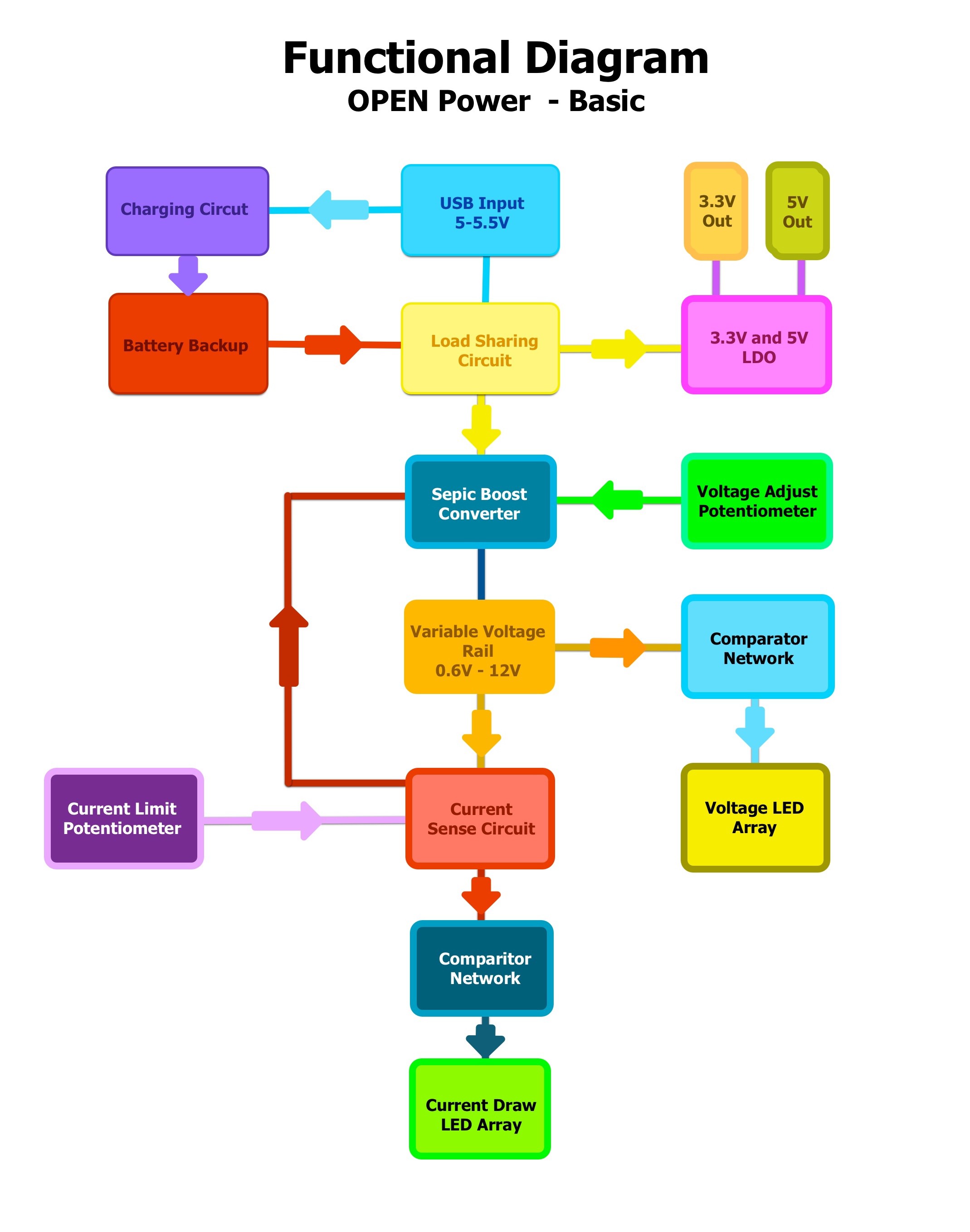
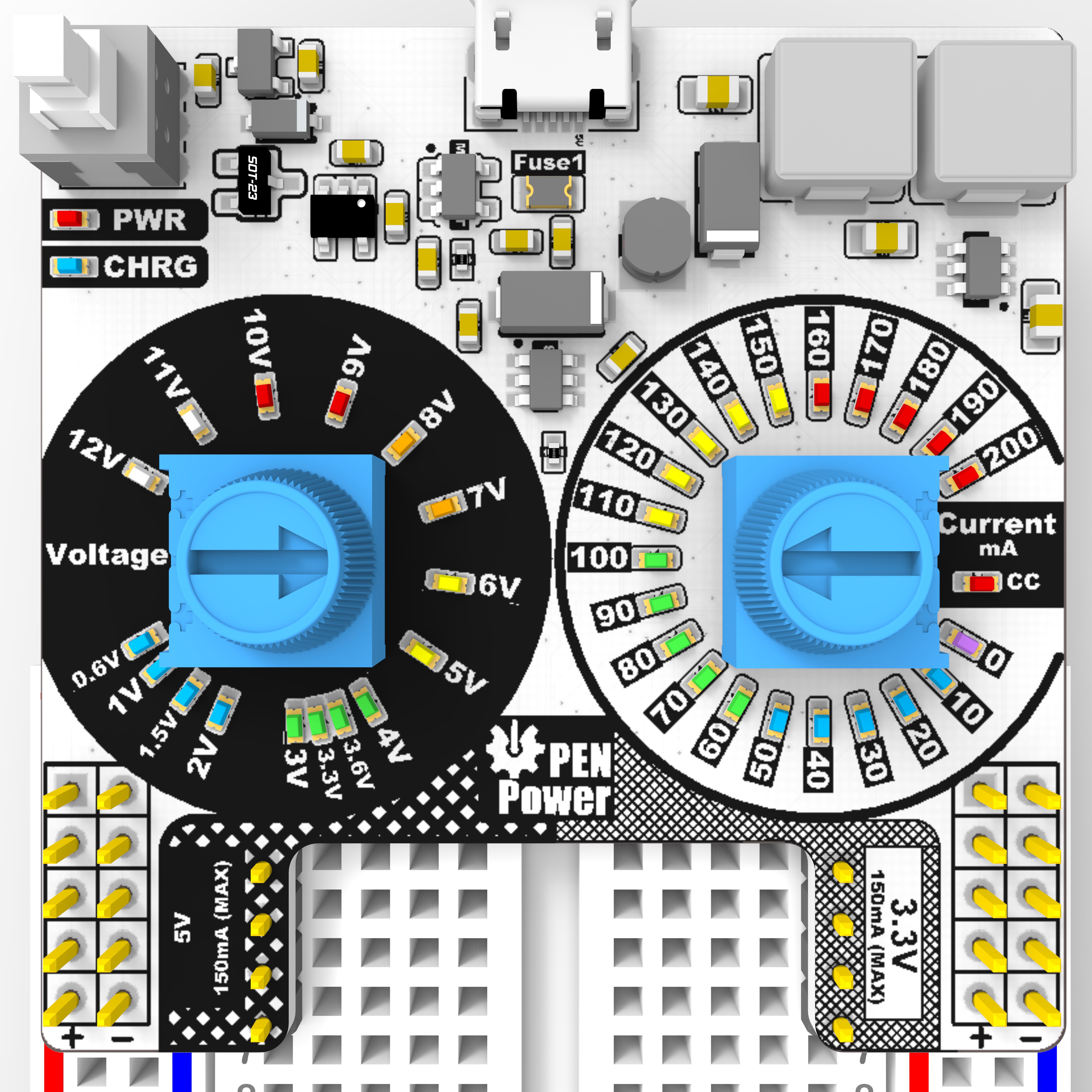
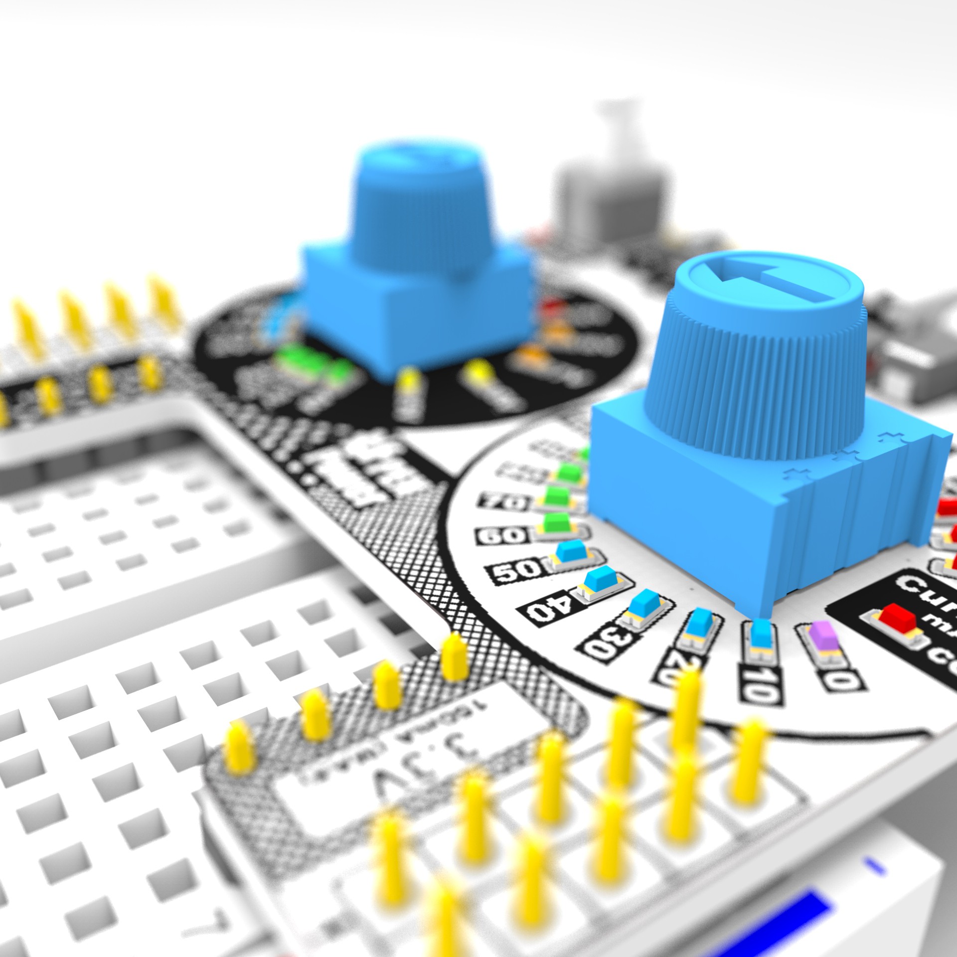
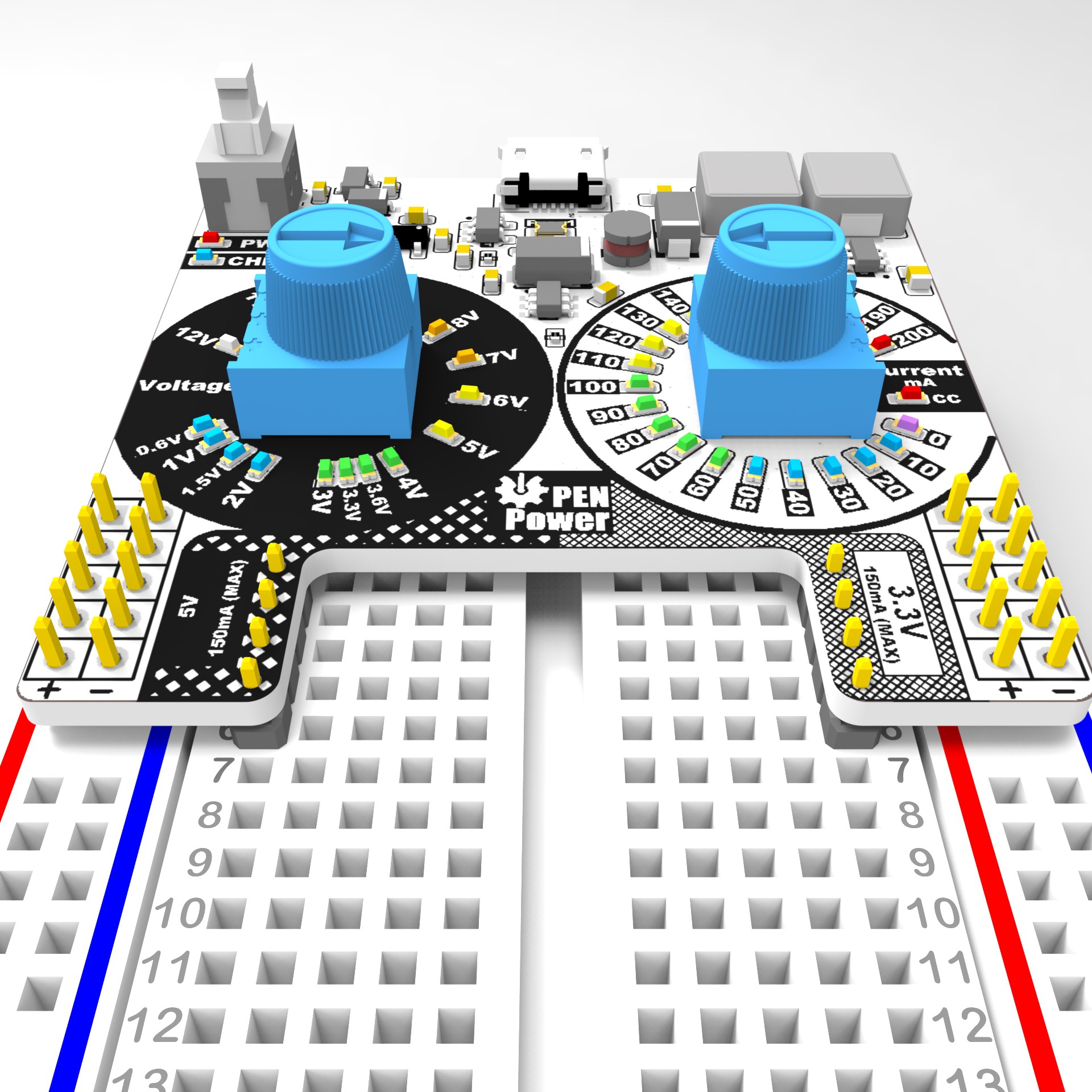
Prototype 1C implements a constant current feature by sensing the ground current and toggling the Feedback pin to the SEPIC converter. If the current exceeds the value set by the current knob the Feedback pin is toggled high reducing the voltage to maintain the current.
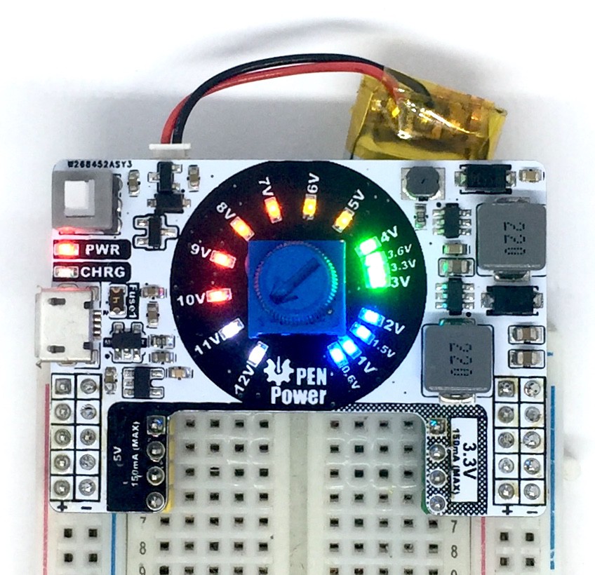
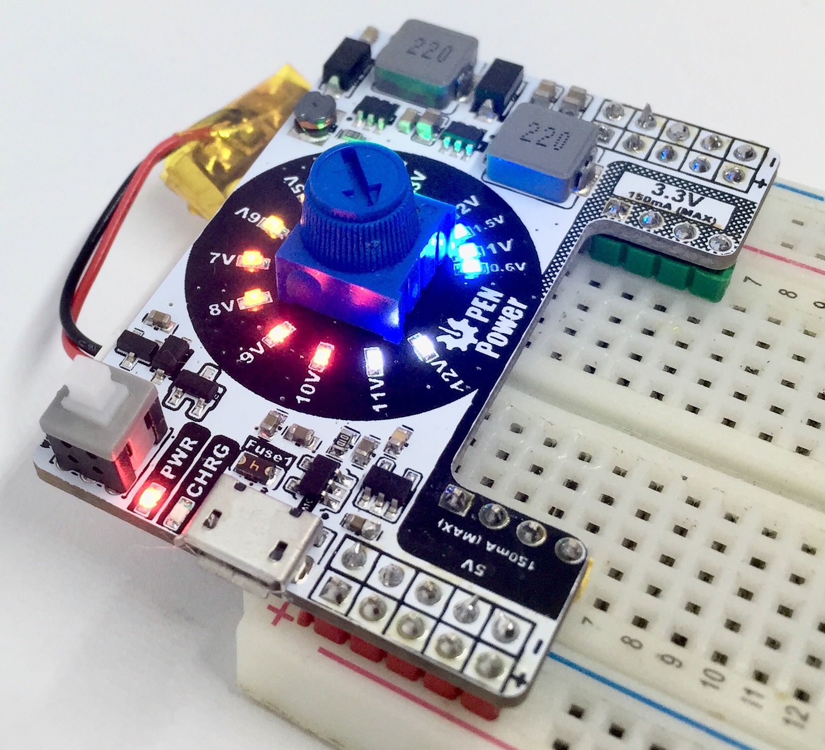
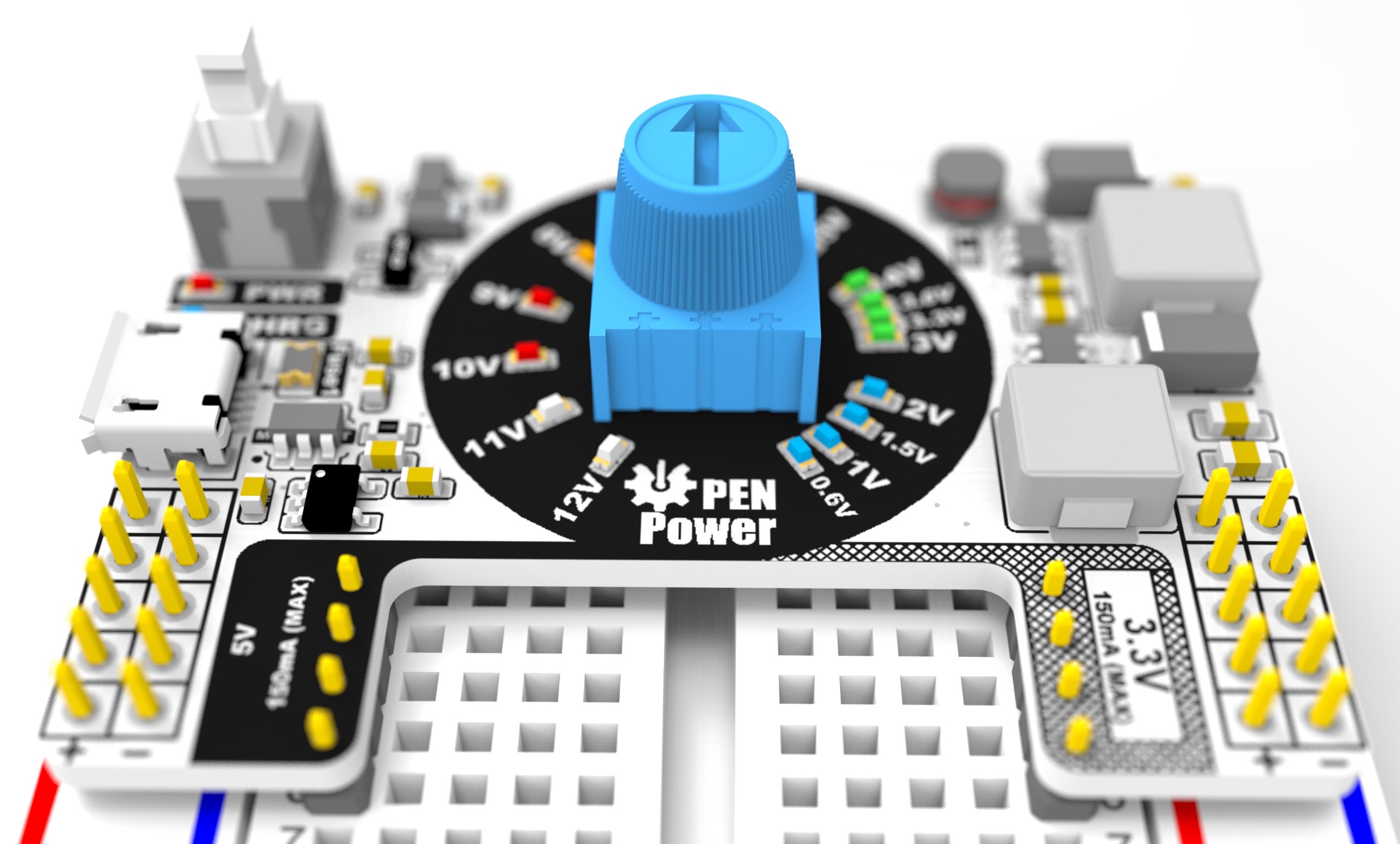
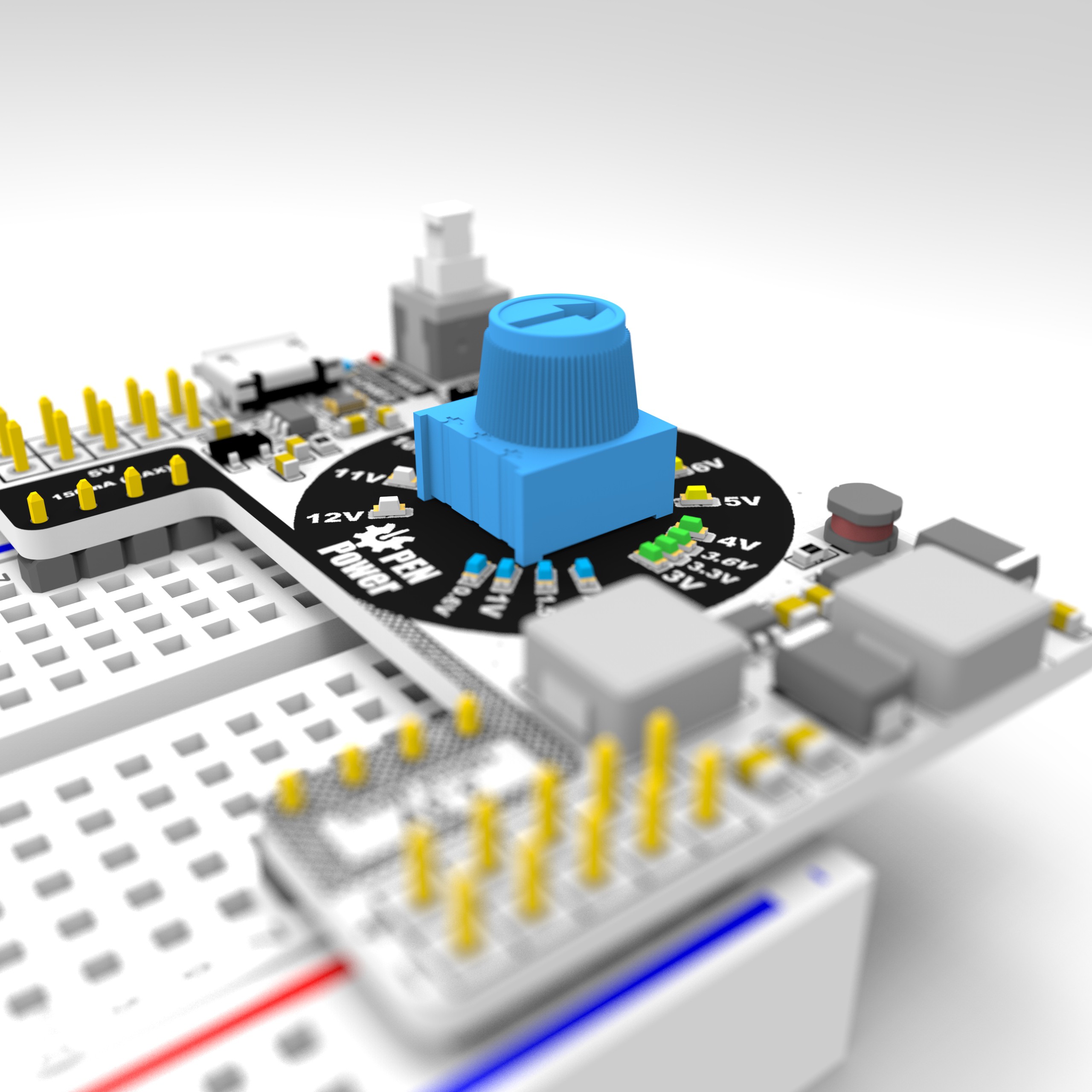
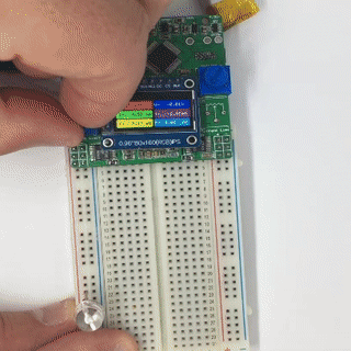
Prototype 1B Makes improvement to the 5V boost converter as well as orients the LEDs arroung the potentiometer. Because the Potentiometer is very inaccurate, a Trimmer potentiometer is used to calibrate the Voltage knob to the LEDs. Calibration method will be developed. 1b was Fabricated and sent to Manufacture,
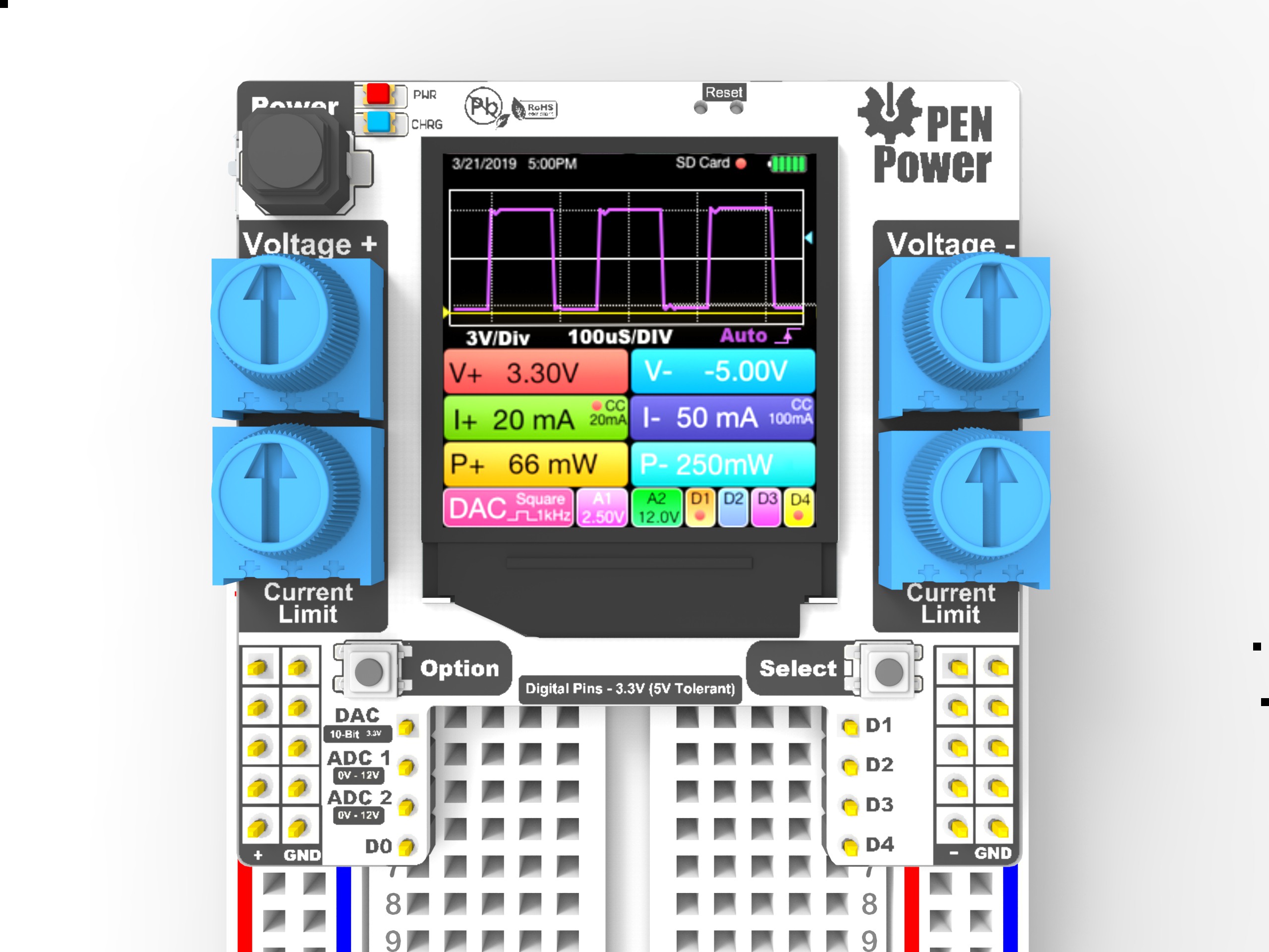
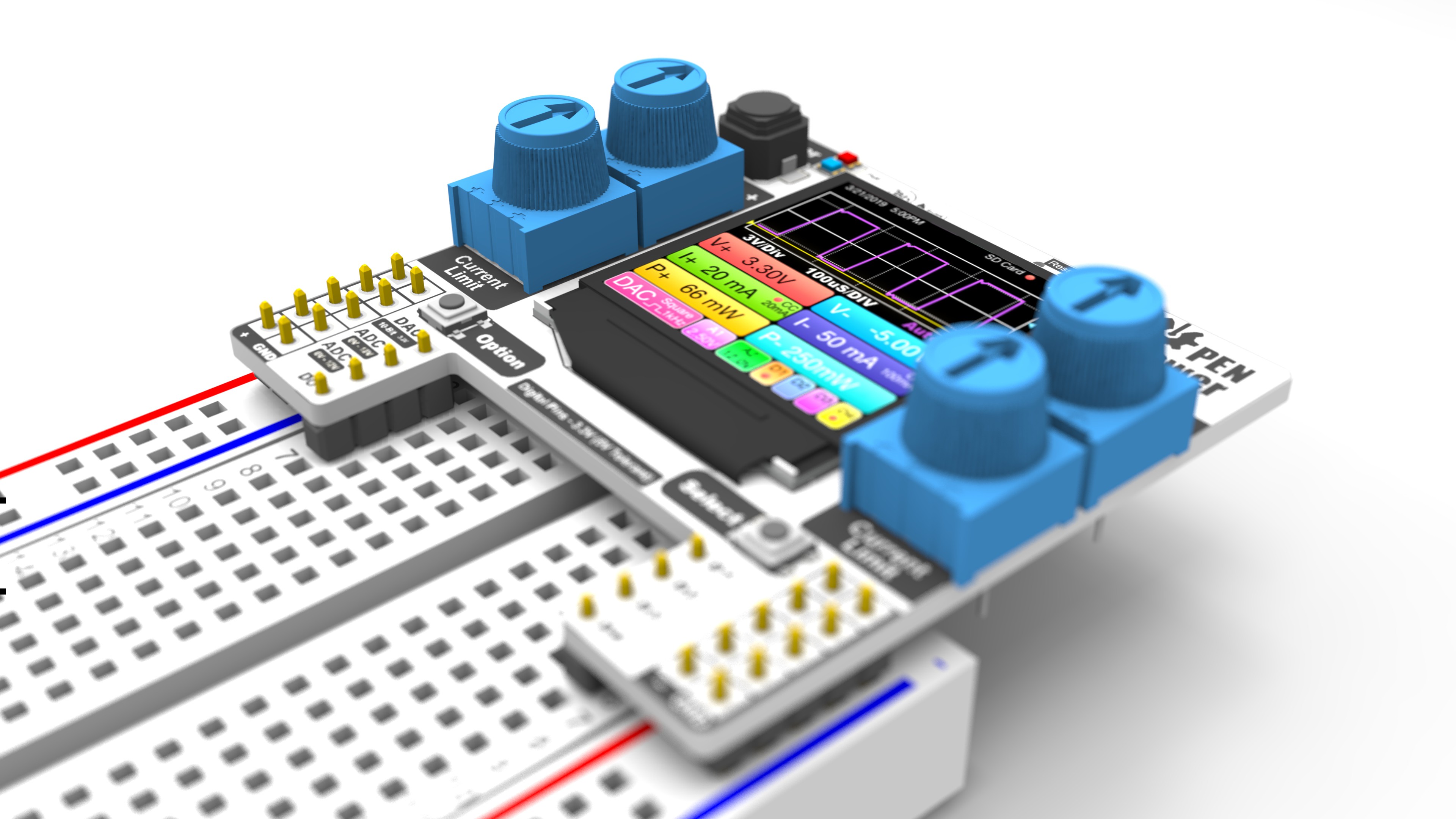
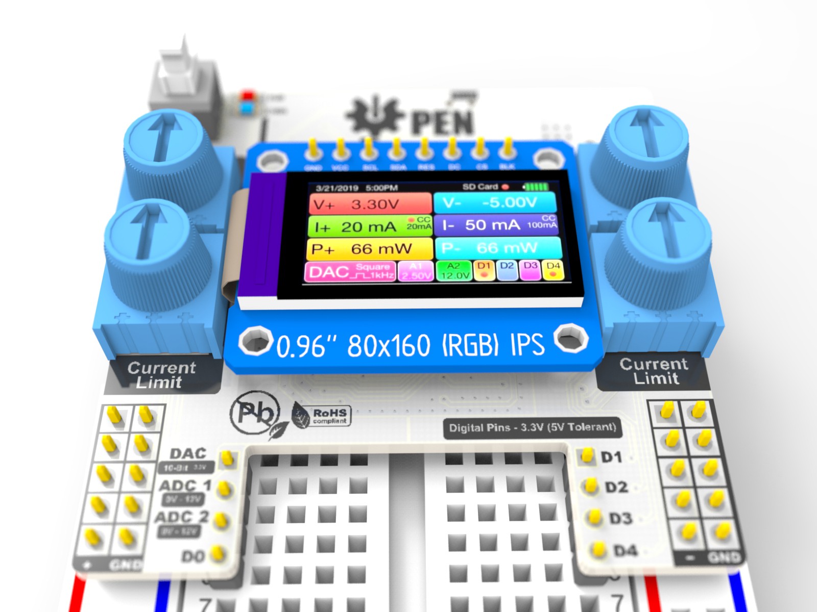
The Samd51 is a bit more complicated than initial thought so i made a Mock-up of Prototype 3 which uses a bigger 1.3in screen which requires the SAMD51 120MHz Clock power. A demo layout of the UI was included in the Render to show it is capable of being a crude oscilloscope or logic analyses .
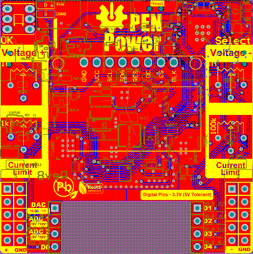
Prototype 3B made the corrections to the negative rail. A new 16-bit ADC will improve the current measuring capability to the 100uA level. Traces were done manually and verified.
 John Loeffler