 CapitanVeshdoki
Target of this project is to create cheap semi-soft linear actuators for everyone to use (^ new design of stripes with magnets) A) Semi-soft actuators would be reliable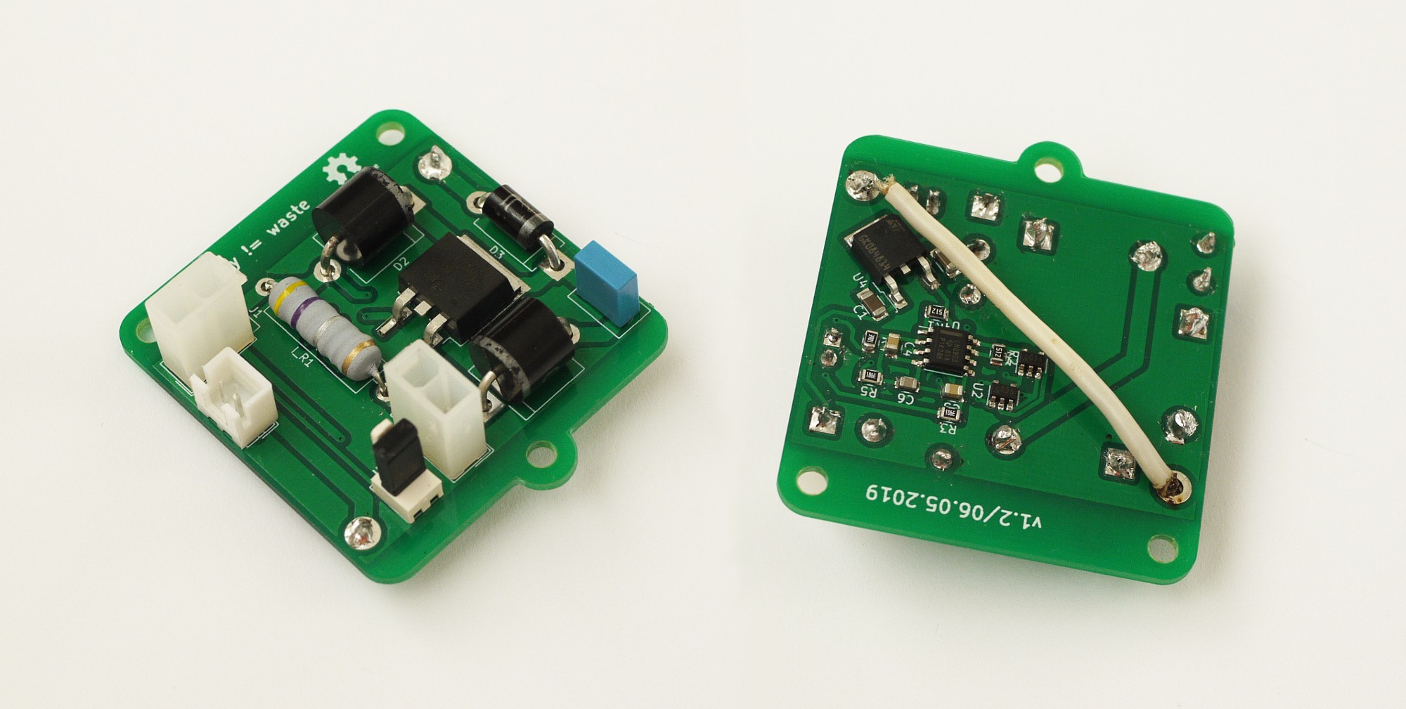
Project has two parts:
1) Structural one, about mechanics
2) Effective control
Structure
Main idea - to use pivoting torque and pulling force at the same time, it works like a linear electric motor. Two electromagnets on each side generate magnetic field, which orients magnetic momentum of each segment of the stripe. 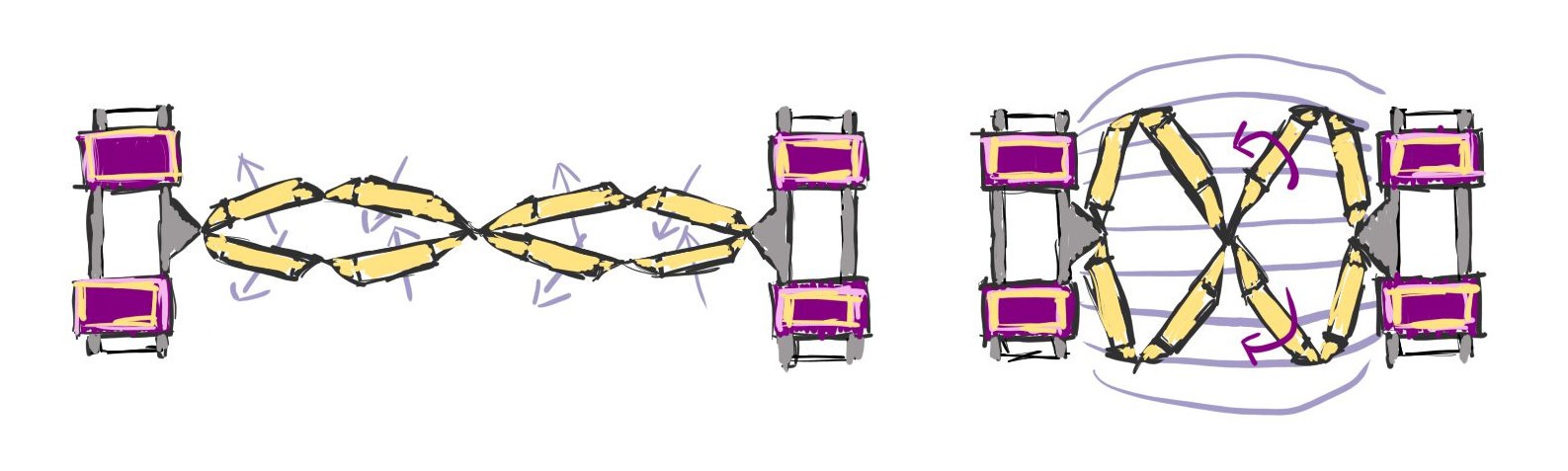
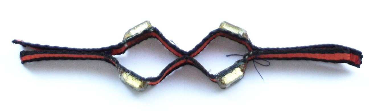
You can read more about production of stripes in logs of project, here I only would say that it's quite simple to fabricate them: you need 3d-printed mold. Then, you pour few liquids (including epoxy) there and clamp nylon stripe inside, as simple as that!
Control circuit and effectiveness
"Are electromagnets effective enough?"
- Yes, you just need to control them properly. We don't have to waste so much energy during their work, my theory is what electromagnet has a top energy capacity assigned to specific voltage which it can achieve and by cramming additional energy inside on top of that you do nothing, what is usually seen as a not energy-efficient behaviour of electromagnets. You can withdraw and insert energy there cyclically without exceeding of any limitations.
During R&D lots of interesting things were found - how electromagnetism works in general and how to "do it" properly. Where are hidden losses, how to avoid them, what is a way to go and what is not.
You can read about it here: http://cafeohw.xyz/electronics/eism/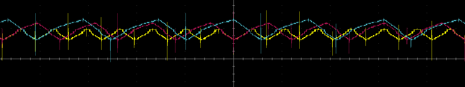
 Benefits
Or why, in the first place? :
A.1) Comparing to traditional rigid mechanics they don't care about shocks of any kind very much, also there is nothing wrong with bending - no requirements for precise placement for them.
A.2) You can parallel them - many hands make light work. If one fails - it's not fatal. And paralleling rigid motors isn't simplest task.
B) They can be fast
C) Why do you need to simulate muscle with complicated math models, if you just can use something, what is very close by design?
0%
0%
linear actuations for everyone!
cheap artificial pseudo-muscles here
Become a Hackaday.io member
Already have an account? Log in.
Just one more thing
To make the experience fit your profile, pick a username and tell us what interests you.
Pick an awesome username
hackaday.io/
Your profile's URL: hackaday.io/username. Max 25 alphanumeric characters.
Pick a few interests
Projects that share your interests
People that share your interests
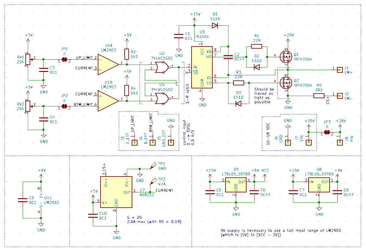 That version won't high voltage very much, main focus was onto providing lowest possible resistance near Q2. 40V IRFH7004 were a best choice from what was widely available in my country. Higher voltage means higher efficiency, but hey, most of benchtop power supplies are 0-30V or close to that, should be fine : )
 It should look something like that. Important to notice, that PowerPAK-8 housings were not devoted for high-current performance, but only for extremely low channel resistance. Actually, Q1 can be any el cheapo mosfet, only Q2 is critical, like that it looks cooler, though, ahaha
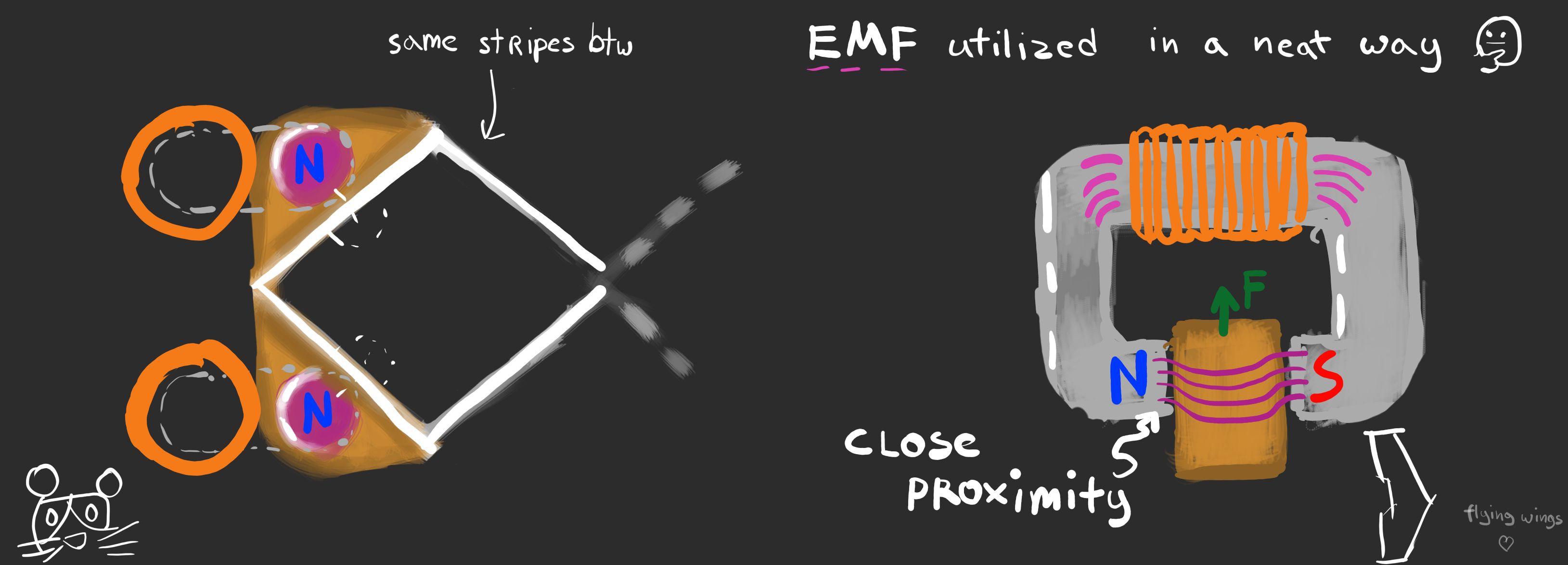 There, poles of an electromagnet are pretty close to poles of a permanent magnet (or steel bar), with that in mind it's closer to electromagnetic locks, while by trying to align magnets, it still has somewhat nice operating range.
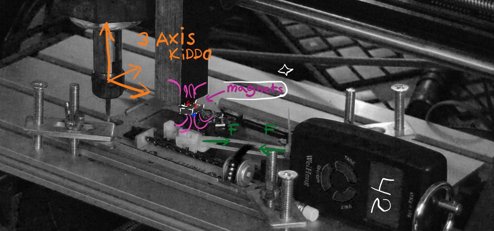 As I use parts from an old disk drive as a linear rail for magnet, it had a very noticeable friction. Also, linkage between scales and a moving magnet wasn't perfect, as it tended to be springy...
 As you can see, gap affects performance very much. I can make an educated guess that it would be full holding force with a gap shrinking to zero. That means that some tolerance in making artificial muscles, as it is for now, is needed to make them perform well
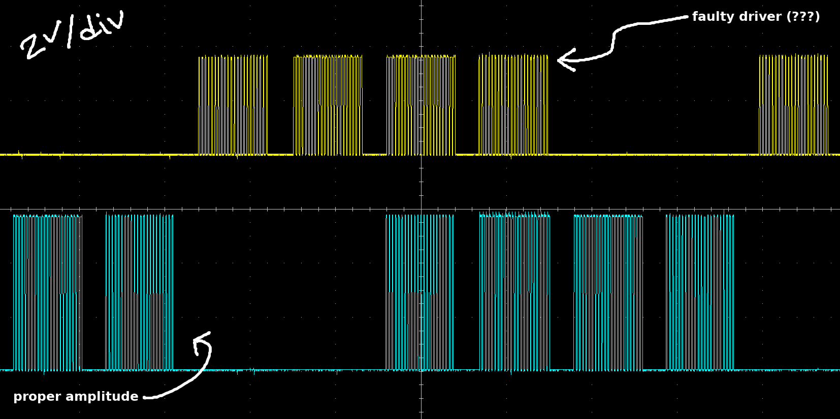 It never got sufficient voltage to fully open. I have no idea why one of sides died this time, or maybe it's components around or flux remained on a PCB? Hope I would find a reason. If not - I will make new PCB for trials with dip panels for drivers to change them without tedious unsoldering procedures.
  Designed to measure thrust generated by a propeller, for that purpose there is an electronic weight in place. Why thrust, you may ask? There is an interesting relationship between thrust and output power - it's perfectly linear. If that setup would generate more thrust with methods suggested before, it would mean that it is more effective, definitely. Even through it seems to work, it should help to get more convincing numbers, I'm not talking about power measured in watts, since it requires different rig, but in terms of how output power relates it does it's job.
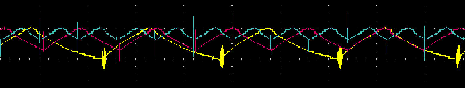
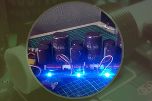
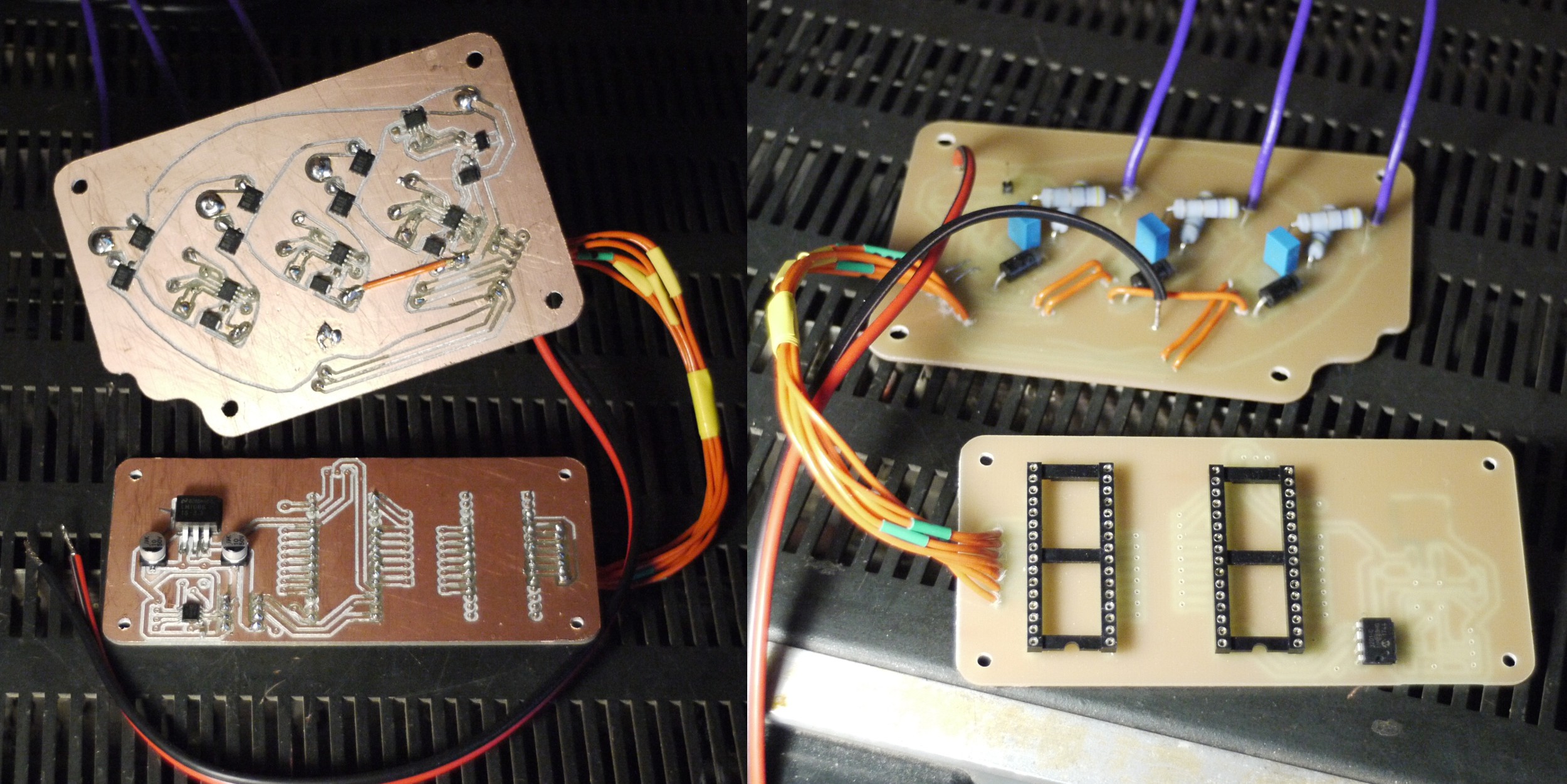 PCB at the bottom would serve as a measurement tool for testing bench, it has 12bit DAC and instrumental amplifier with adjustable gain to measure torque. More of that in next updates as there is some problems with that controller. It works, overall, but "rings" like crazy. Here is a photo with re-soldered FETs and voltage on transistor's gates:
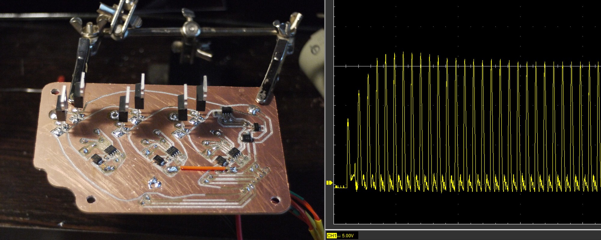 Looks suspicious! I don't know what's the reason for that. Maybe, protective zener diode cause some problems. But the fact is that even without motor connected it drains noticable current and produces sound. Sound which is normally produced by a great currents flowing through tiny components. It's not a norm : )
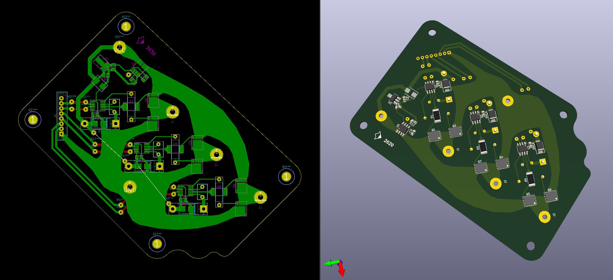 Had lot of fun tracing that stuff! Aside of queer shape, it should have a damn good resistance and heat dissipation properties. Inductance should be less as well.
 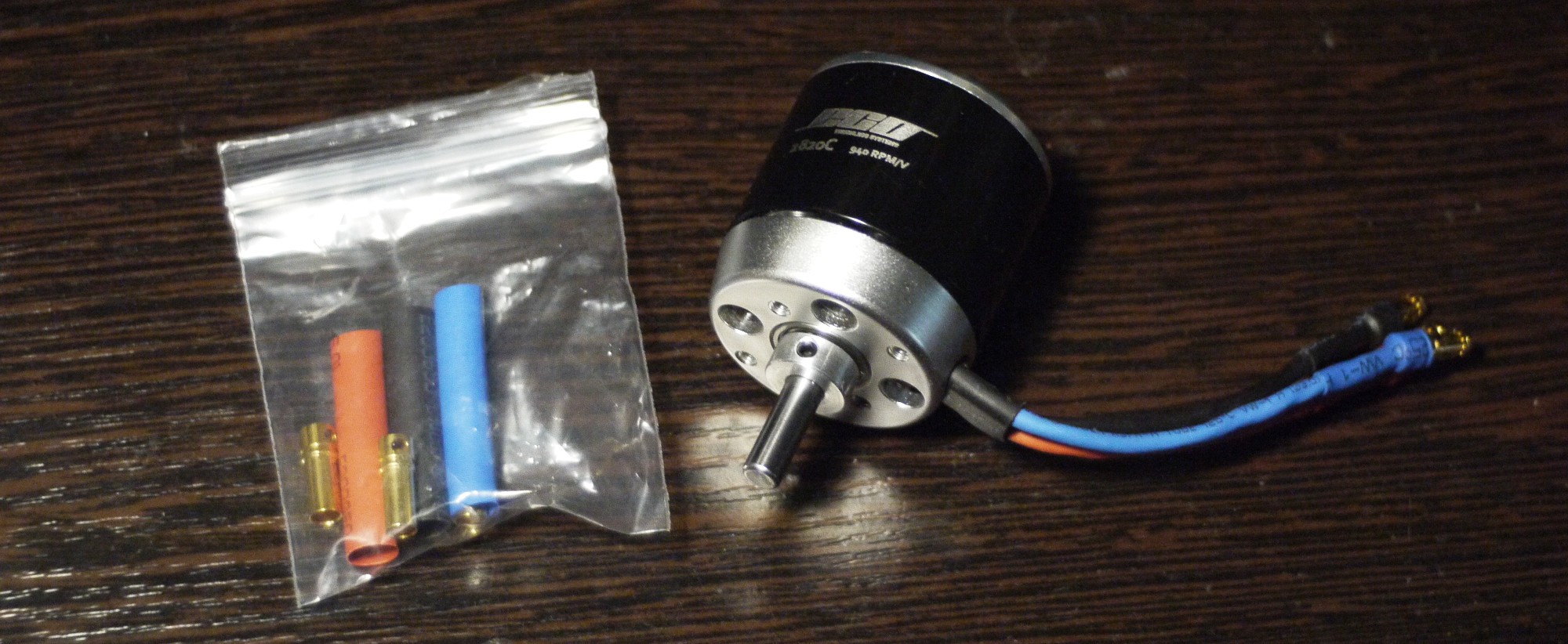 Motor has something around 30mOhm resistance, according to a manufacturer. Curious how it would play out, generally - low resistance would be a benefit, but with MCU-controlled board I'm pretty concerned about switching frequency. It's really easy to get sky-high currents that way x)
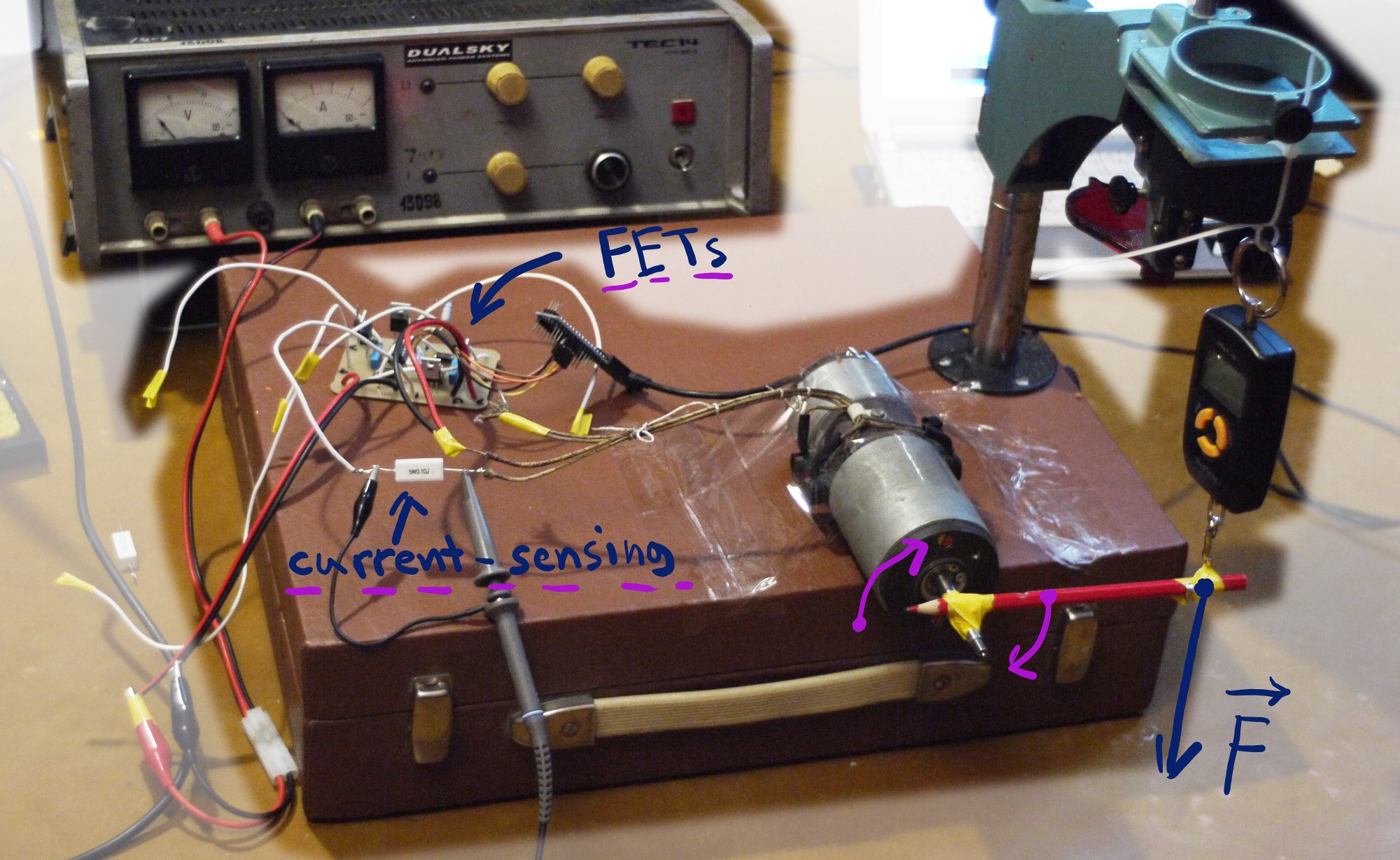 That photo magnifier was unused for years! But it came in handy, finally
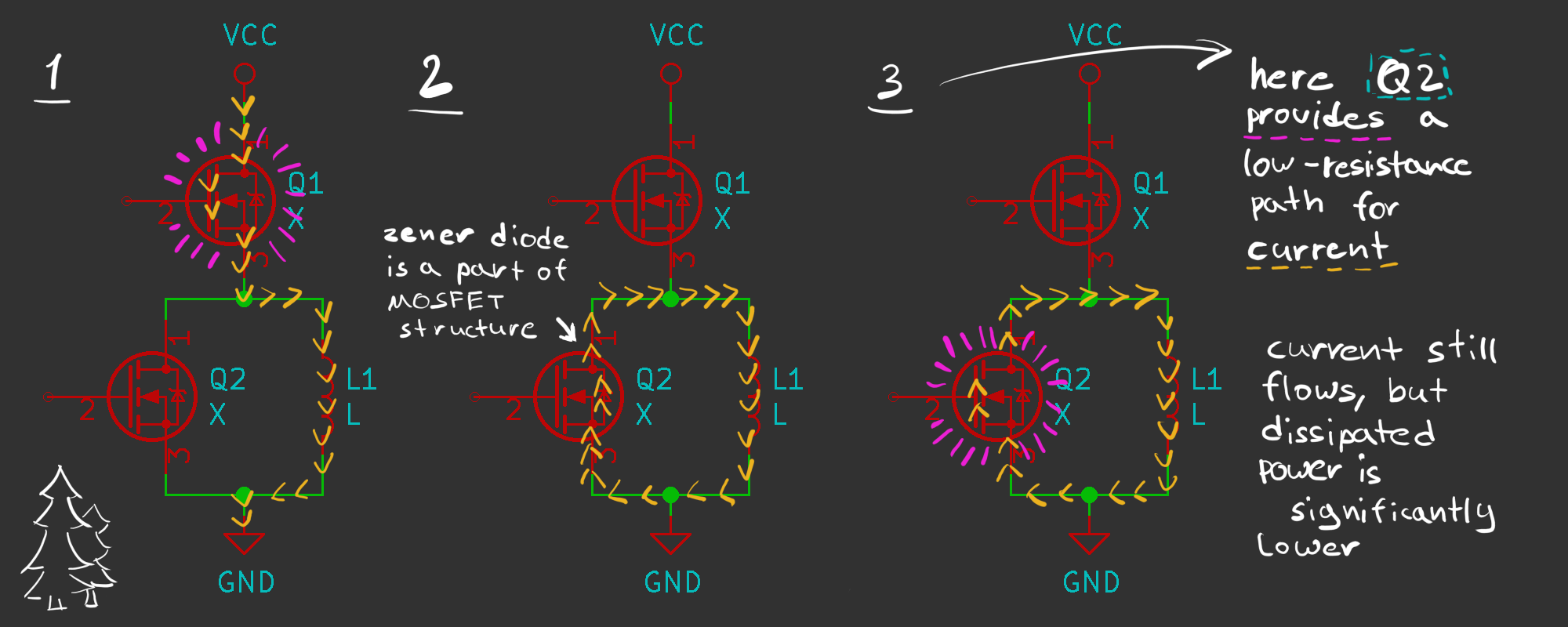 In theoretical Part 4 we came to a conclusion, what voltage drop affects discharge time significantly. Must-read, but simplified - coil tries to produce constant current while discharging and it's a very easy task if voltage drop is minimal. One approach is to use a diode, however, 0.4V is pretty high. And that is where MOSFETs come to play, acting as a low-resistance load.
 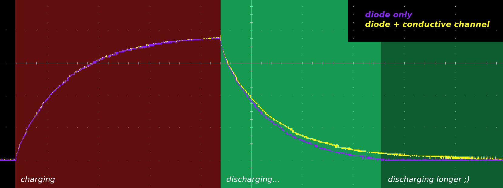 As you can see, it discharges about two times slower. It might be not very obvious, since discharging curve is really steep at the start, however, looking at the end of discharging process - advantage is pretty clear.

 Xylitol
 DeepSOIC
 sky-guided
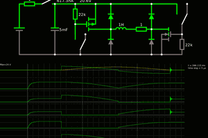
 Yann Guidon / YGDES
Excellent work! I'll definitely be following this project closely. It seems you are progressing rapidly now, and the muscles are even more efficient.
Any chance the 3D mold files or PCB schematics will be made available anytime soon? I'm eager to join in on developing these actuators for a robotics application. I think they would make a suitable alternative for brushless motors if the torque could be maximized. Much more power efficient too!