 CapitanVeshdoki
-
Long time no see : )
06/28/2019 at 14:05 • 0 commentsI wasn't there for long, but that's for reason! I made a small vacation for myself, also - 3d printer arrived. So I've been working onto fixing some printing issues, caused by troublesome Z-axis mechanics. Now everything seems to be fixed, I regained access to 3d printing stuff, hooray! :)
Of course, I tested modular electromagnets
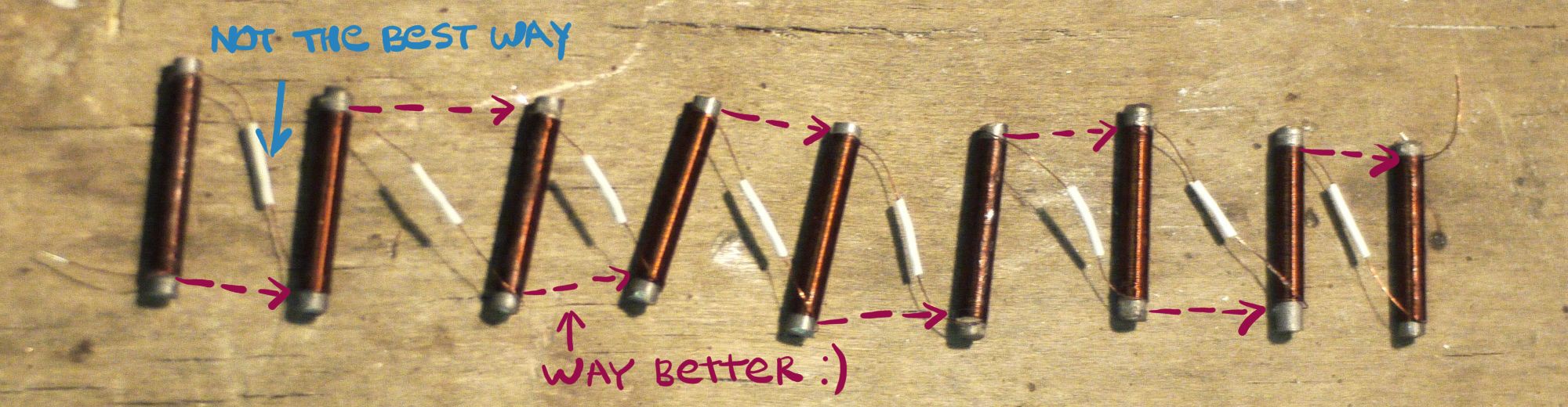
It seems, that I failed to produce reasonable design of winding, ahaha![]() So it's must-have thing to wind half of them in opposite direction! Otherwise, you would need to connect opposite sides of coils, leaving loooong wiring between, that isn't pretty at all! Now I am into designing cheap winding machine for that purpose, motorized this time
So it's must-have thing to wind half of them in opposite direction! Otherwise, you would need to connect opposite sides of coils, leaving loooong wiring between, that isn't pretty at all! Now I am into designing cheap winding machine for that purpose, motorized this time
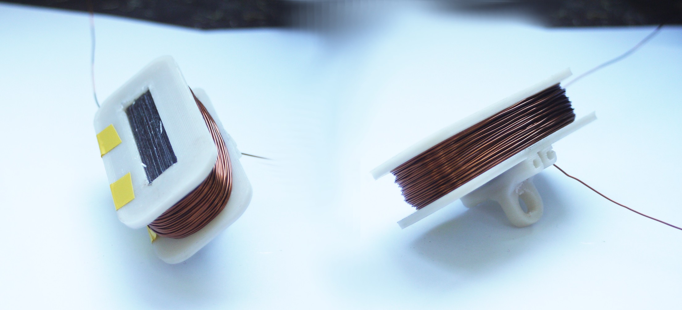
I've made only one half of magnet, because second half operates similarly:![]()
![]() And I want to say, that it performs very well! Self-proclaimed "modular" electromagnets are pretty small and light, use a little amount of cooper wire and also pretty strong compared to beefy convenient electromagnets, even with nails used as a core material. So I can say, that with nice core material or control circuit, which can sustain powerful magnetic field, it's a win : )
And I want to say, that it performs very well! Self-proclaimed "modular" electromagnets are pretty small and light, use a little amount of cooper wire and also pretty strong compared to beefy convenient electromagnets, even with nails used as a core material. So I can say, that with nice core material or control circuit, which can sustain powerful magnetic field, it's a win : )
Now about core material, I thought a lot about using induction heater and I already have one, of course, but this method requires deep vacuum pump, I think I can do it without low pressures.![]() Using H2 intake as a heating element with O2 originally in chamber - it's the most simple solution, which I found, only requires some high-temperature clay, insulator (rubber?) and electrolytic cell.
Using H2 intake as a heating element with O2 originally in chamber - it's the most simple solution, which I found, only requires some high-temperature clay, insulator (rubber?) and electrolytic cell.
Plus remote control for the reason of safety, of course.
It's possible to pump high amounts of energy into coil with control circuit, thanks to great efficiency. And probably... It's possible to use that instead of hardcore core materials, needs to be seen! To test that, I need to establish adequate bootstrap driver, because IR2117 has zero passion to work! >:{
(probably it self-destroyed at some point, I need to built similar thing on NPN-PNP transistors now)
With nice core materials it would work best anyway, so it's good to have ability to produce such things! -
log(18)
06/08/2019 at 18:04 • 0 commentsOn last week I played with coils, and played a lot
Now I have 18 coils, all what's needed to complete one modular electromagnet:![]() As I'm too lazy to wind them by hands, I had some extreme prototyping experience ->
As I'm too lazy to wind them by hands, I had some extreme prototyping experience ->![]() Yeah, it's winding machine made from a building kit! Works surprisingly well!
Yeah, it's winding machine made from a building kit! Works surprisingly well!
I would design something more reliable later, of course, )
Since I have some troubles with accessing 3d printer and drilling machine for now, I haven't completed modular electromagnet yet, however I fixed problem with transistor's opening!![]() This is how schematics looks now. Nothing changed in current monitoring circuit, but now we have IR2117 (or IR2118) MOSFET driver here. What it does - it provides extra voltage over voltage on capacitor C3, so voltage difference between Gate and Source stays positive then needed even then transistor is in high side switching mode. That means, that transistor is fully opened, outputs that needed and dissipates less heat as well, so it wouldn't require hardcore cooling : )
This is how schematics looks now. Nothing changed in current monitoring circuit, but now we have IR2117 (or IR2118) MOSFET driver here. What it does - it provides extra voltage over voltage on capacitor C3, so voltage difference between Gate and Source stays positive then needed even then transistor is in high side switching mode. That means, that transistor is fully opened, outputs that needed and dissipates less heat as well, so it wouldn't require hardcore cooling : )
Also, there is additional transistor Q2 - while opened, R8 and R7 work like voltage divider and voltage on IR2117 "IN" pin is close to +0.4V (R7/R8 * +15V), then Q2 closed, we have +15V there.
IR2117 has different logic levels:
- low 0-6V
- high 9.5V-20V
So it's necessary to convert 0-5V output from TTL's to an appropriate level, that's why Q2 is needed.
I think, tracing PCB's with MOSFET controllers only is OK for test purposes, so new revision of control circuit's PCB would be later, I don't want to waste time waiting for a delivery. And I want to go camping next week, so modular electromagnets experiment results release is going to be delayed ) -
Troubleshooting
06/01/2019 at 11:48 • 0 commentsIt seems what I've figured out what's gone wrong with new PCB
For the reason, I use transistor to cut off connection between coil and power supply, ground is connected permanently and control circuit tracks current on electromagnet to choose duty cycle properly.
That's why transistor works like common-drain-amplifier.
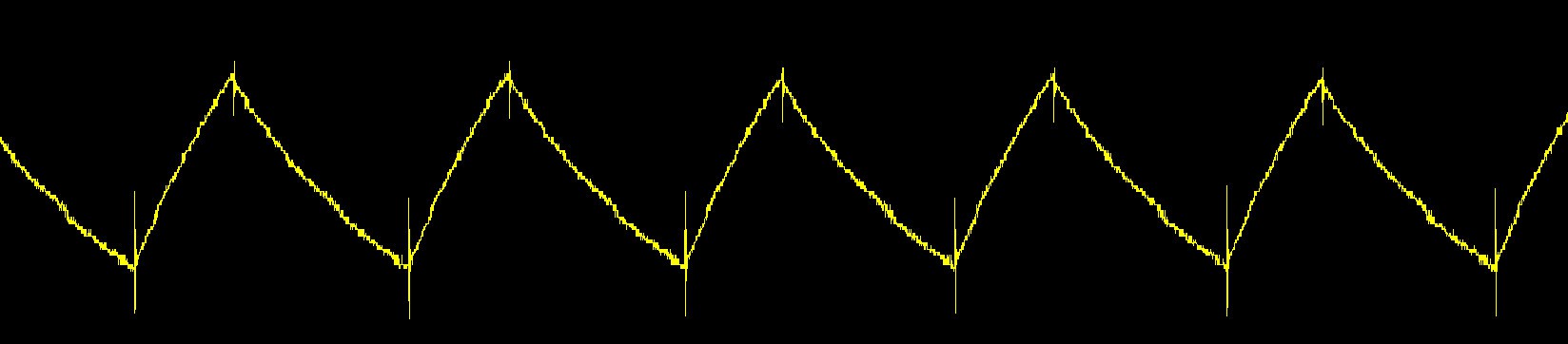
Drain current derives from difference between gate-voltage and drain-voltage multiplied by forward transconductance of a transistor, so drain voltage cannot be greater than gate voltage minus voltage drop on gate-drain junction, that's why you can see something like this:![]() Yellow - control voltage, from logic gates (5V amplitude)
Yellow - control voltage, from logic gates (5V amplitude)
Violet - drain voltage
Well, what's next? There is three options, actually:
- One option is to find a way how to use common-source-amplifier schematics there, but I'm kind of skeptical about it, because such a control method leaves many limitations
- Second option is to amplify control voltage to V_TRG level, by additional transistor, which works in common-source mode. This should work nicely
- Third option is to use solid-state relays, they are cool, but kind of expensive, so I don't think that this is an option for small and not-so-powerful actuators
P.S. You might wonder, why I made such a mistake. Well, everything worked well on a previous design! I have no idea why and how, because now I see that it shouldn't. However, it worked
Maybe it was some kind of magical interaction between Q1 and Q2, uhuhu : ) -
PCB's there!
05/29/2019 at 20:03 • 0 comments![]()
Hello everyone. After a couple weeks I've got my PCB's and assembled first one.
Big thanks to PCBway, never seen so much enthusiasm from a PCB manufacturer
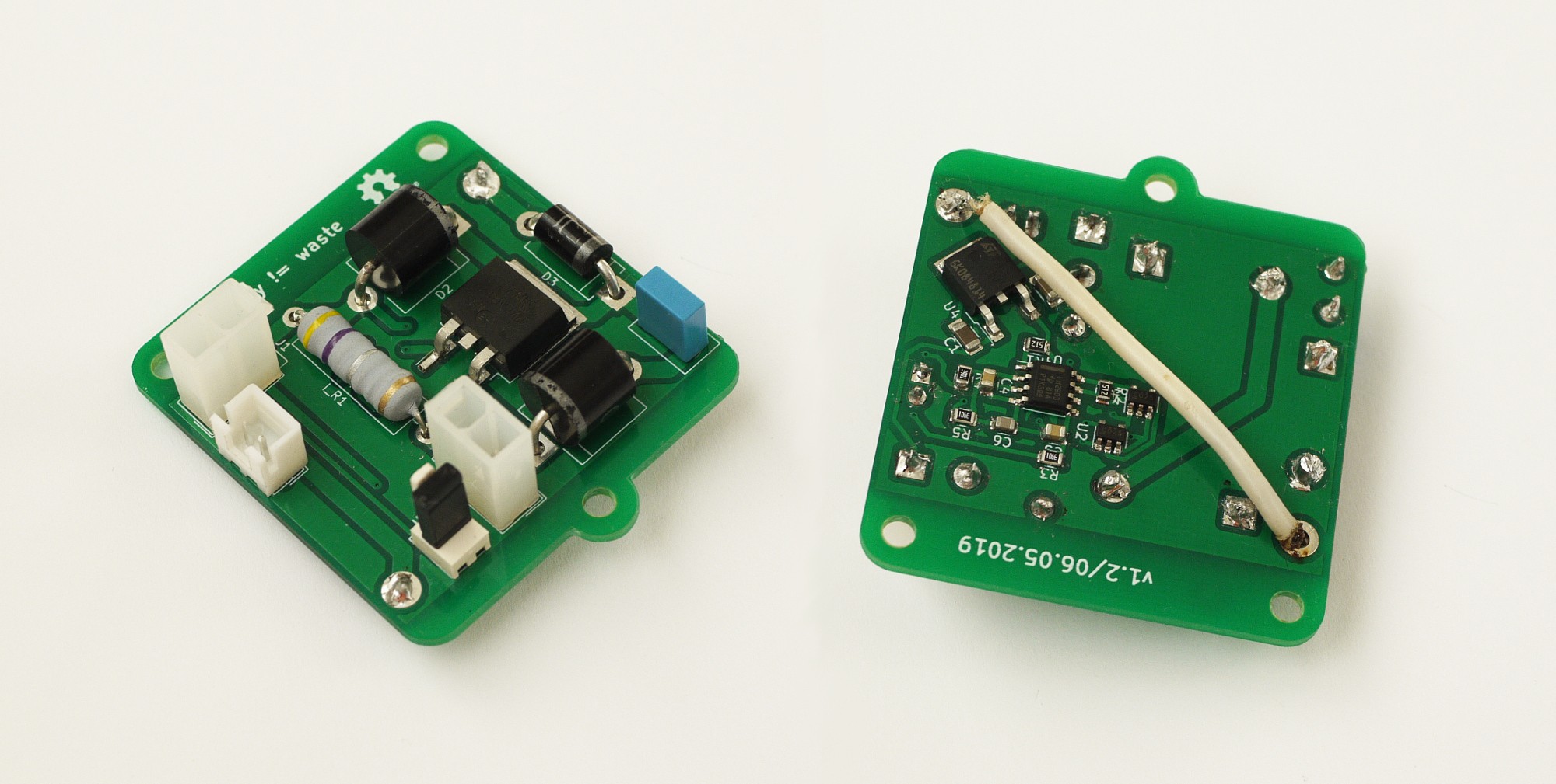
Quote: "power of chaos" - such a pearl! It was a fun time talking with you, guys : )![]()
^ wire here - bridges VCC and V_TRG, leaving possibility to use high voltages in coil circuit
without bad outcomes for the little 5V linear stabilizer, used to power up logic circuitry!
I was able to control it via MCU (Arduino) directly, hooray!First of all - never trust PWM->Voltage article on Instructables. It's totally wrong - instead of using 0.1uF capacitor in Low-Pass filter, I highly recommend 10uF, it is fixed in project files which I gonna upload in future, however, I think I should mention it
Everything works?
![]() Well, not that simple! All circuitry, responsible for a giveaway-reserve energy cycle works fine - it generates control signal in right time and then sends it to the gate of MOSFET
Well, not that simple! All circuitry, responsible for a giveaway-reserve energy cycle works fine - it generates control signal in right time and then sends it to the gate of MOSFET
And then strange thing happened - IRLZ44NS (that mosfet) fails to output more than 5V:
- source voltage - is OK, much greater than 5V
- it obviously not from logic elements, how they can output half-amp currents? no way!
- stabilizer heats? not at all, but MOSFET does
FETs were connected similarly back in the days, then I tested previous version. If anyone has a theory why that can happen - would be happy to hear, because I have no idea at the moment
Here is schematics again, if needed:![]() Magical thing! Not unsolvable, anyway : )
Magical thing! Not unsolvable, anyway : )
[probably, I just messed up soldering, who knows] -
Electromagnet investigation headquaters (OwO )
05/27/2019 at 21:49 • 0 commentsIn previous log I've posted an idea - how to improve current->field transformation efficiency via something except of a good core material. So I experimented with that for a while and it seems to work.
So, what I've got for now:
1. Program
First of all - I've wrote a code, which calculates magnetic field in a core, corresponding to shape of a wire.
Because most of calculators have no idea about shape and it's crucial in that case : )
Also, thanks to Florian Festi, who shared a nice way how to think about coils, you can check it in comments under previous update, it's really very helpful!Results (coil performance, one layer, same voltage, different wire diameter):
![]() That is very interesting here - how better distribution of area (through which current flows) in case of small wire diameter increases efficiency drastically. Overall, wire is closer to the core and it almost reduces effect of current drop, in case of supplying with the same voltage:
That is very interesting here - how better distribution of area (through which current flows) in case of small wire diameter increases efficiency drastically. Overall, wire is closer to the core and it almost reduces effect of current drop, in case of supplying with the same voltage:
75% current drop leads only to 35% magnetic field drop!
It means, that by using greater voltages (like 100V except of 30V) we can achieve amazing performance even with a bad core material, in case of single-layer coil! Of course, there still a question about heat dissipation, however, all experiments shown, that this stuff not likely to be heating much with such amazing control method, ahaha :)
And of course I experimented with that a lot, experiments show almost similar results.
2. Electromagnet design
Of course, I'm on my way to build one of this magnets. I made 18 cores (from nails this time, but who cares, if it would work with bad core material, it should do it best with nice pure-Fe cores later, obviously)
So now I'm on stage of wire-winding. Here is final design comparing to previous one:![]() Looks kinda weird, because it is in-scale and new design is kind of smaller :)
Looks kinda weird, because it is in-scale and new design is kind of smaller :)
I would upload hi-res render to the description, I really like that Sci-Fi look.
You can see there improved stripe-fixation mechanism as well, which I described in previous updates
3. Control circuit's new version PCBs!
Yeah, I've received them today! Update about them - coming soon
In two days, I'm not sure what I would have time to solder tomorrow
I want to test them very much, they are kinda pretty, huhuhu -
Modular... Elecromagnets?
05/23/2019 at 11:01 • 2 commentsYesterday I told, that I haven't found an another way how to improve electromagnets,
It was partly true - I found one way, but I thought that it was impossible due to some reasons. Then I realized, that I might know a solution! And it seems possible to me now.
In previous logs was the idea - closer you place wire to a core, more efficiently it use current to induce magnetic field into core. So how we can maximize surface area of a core to place as much coil on the first layer as we can?
Solution for that was something similar to radiators which dissipate heat. However there was one problem - on the different sides of wire you have field with opposite direction, it weakens nearby electromagnets.And today epic idea came to my head - it's right for straight wires, but around curved ones much more dense field is on the internal side of a curve, while outside it's kind of a weaker field!
![]() I tried to show it on the left side, you can see one turn of a coil there. Seems logical!
I tried to show it on the left side, you can see one turn of a coil there. Seems logical!
And what are our benefits?
- we achieve amazingly big surface area here!
- with help of this surface area we can use only first layer around each coil
- it delivers amazingly strong field inside of a coil
- so magnet becomes more powerful
- we can construct cores of different shapes using similar elements!
- coils are placed INSIDE of a core, so it makes electromagnet more compact
Oh. And pretty sorry - I made a mistake in previous logs, thinking, that more current is more important then number of turns. They are equally important!
But diameter of wire affects resistance significantly, so by reducing wire diameter two times, we increase number of turns only twice, while resistance increases 4 times.
That's why I had an idea, that current is more important.
So now, before arrival of induction heater I can check this theory also.
It has some sort of Sci-Fi look with all those honeycomb shapes! huhuhu -
Long-term log
05/22/2019 at 18:05 • 0 commentsHello everyone! This log gonna be long-term one (not long)
Why? Well, of course there would be an update about new version of control circuit, which should arrive .. in some period of time (says "Export of international mail" since 20th of May), but periodic logs about how things going are gonna be less periodic, because almost everything what can be done to make first version of an actuator a reality was done, really:
- control circuit is fully tested, it retains energy well and controls everything what needed, as beta-version it works amazingly well and I hope it gonna work even greater with a new PCB : )
- technology of stripe manufacturing is fully developed, reliable and easy, all problems were fixed, I like current design of stripes too, as it provides great pulling force![]() ^ this picture represents duel with fluid dynamics and glorious victory (thanx, corn syrup!)
^ this picture represents duel with fluid dynamics and glorious victory (thanx, corn syrup!)
Of course, I've measured a pulling force, now I have a nice equipment for that!
Everything there is measured with 20kg magnets on each side and 10x10x4mm inside:
- stripe can reduce it's length at least on 60%. more? possible, but with different proportions
- stripe provides from 500 to 660 grams of pulling force on it's own, I found that pretty persistent!
- attraction force between big magnets (or electromagnets) increases pulling force - 1kg to 1.5kg
Only one thing is not ready - electromagnets. Of course, I've done one and showed it in previous log, but it still can't provide significant attraction forces - it has flaws. About them:![]() First of all we need to have a look at coil itself. Wire here (along with current) works as a source of electromagnetic field, shown on the left side, and further we place core from wire - weaker field becomes. We need this field to orient magnetic field of our core's material atoms, which works as an "amplifier".
First of all we need to have a look at coil itself. Wire here (along with current) works as a source of electromagnetic field, shown on the left side, and further we place core from wire - weaker field becomes. We need this field to orient magnetic field of our core's material atoms, which works as an "amplifier".
That means: less layers of wire we have in our magnet - more efficient use of current we get.
Also, material of core really matters, parameter called permeability is significant - so we need to get best material we can. That's why I want to use hydrogen chamber, to make Fe annealed in it. As I told in previous logs - such a material has one of greatest characteristics which is possible to get, so it's quite helpful in that project, but requires some time and additional equipment.![]() Also, I want to upgrade coilformer, because it wasn't optimal
Also, I want to upgrade coilformer, because it wasn't optimal
As stripe attracts to the core (mostly), fixating stripes directly to the core is the best decision. I want to do that by drilling 4 holes in the core and using steel wire (or something similar). I hope what my drawings are understandable enough - you can see there stripe is being held by a steel wire - compact and lightweight.
Current prototype of an electromagnet showed, that winding wire onto rectangular shapes is quite questionable process - it leaves gaps between core and coil (this is very bad), so i think, what I would use something between ellipse and rectangle for that purpose, then I would figure out how to cast properly.
Also, I would be happy to find someone, who is really into designing electromagnets!
And maybe has an idea how to make them extremely powerful, as never before : )
As they are effective as never before now, thanks for that decent control circuit,
I've thought a lot about that, I still can't find another approach, except of using better core material
It would work, howeveeer... I think, that there should be a different way -
Power of syrup! (log13)
05/18/2019 at 14:24 • 0 commentsWell, everyone knows what syrup is. Sweet thing!
Probably it isn't on your kitchen, wide-spread in cakes.
As you may remember from previous update, I faced with capillary effect problems another time - oil just runs away from epoxy. One approach was to change mold some way or to pour more oil. But you know - more oil isn't good for health of an actuator, so I decided to find a way how to prevent runaway with same mold and same amount of oil.
And I gracefully present you this -> !!!![]() I thought that problem was in viscosity... And it surely was!
I thought that problem was in viscosity... And it surely was!
I bought a bottle of magnificent corn syrup and water-thinned it (10 syrup per 1 water) to get epoxy-like viscosity. It's dirt cheap and yes, it has pretty high viscosity, without water-thinning it outperforms epoxy drastically.
Main thing: as a syrup it's just a high-concentration solute, so reducing concentration by water-thinning is a reasonable process. And as you may guess - it's possible to dissolve it in water after hardening of epoxy!
How great! Results are incomparable to results with oil, stripes are bending perfection : )
P.S. I love that it doesn't requires any noxious solvent.
Secondary part about electromagnet, as I've one completed:![]()
![]()
Of course it still has somewhat illogical design, but as experimental equipment it should work. One thing with which I faced - compromise between voltage and current, to reduce heat dissipation on control circuit's semiconductors.
This electromagnet has a resistance of 2.2 ohms, well... :D
Quite low, but it is required from my perspective to have small powerful coil. As you know - inductance rules and induction heater still being delivered, so that's why I can't make cores with high permeability now, sadly
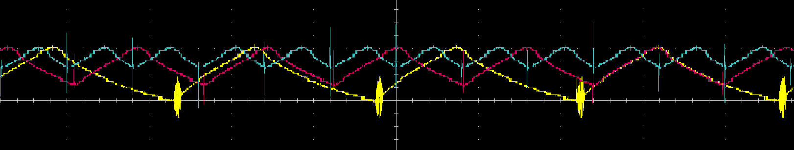
However I made pretty pictures from oscilloscope and first version of control circuit with that magnet!![]() You can see current on coil (reminder: it represents energy of magnetic field), and how boundaries of energy oscillations can be changed with magic of this circuit - here I move lower bound, different runs are coloured differently.
You can see current on coil (reminder: it represents energy of magnetic field), and how boundaries of energy oscillations can be changed with magic of this circuit - here I move lower bound, different runs are coloured differently.![]() And here I move upper bound, different runs coloured as previously.
And here I move upper bound, different runs coloured as previously.
I think it shows it pretty decent now, thanks for greater inductance of a new electromagnet : ) -
log(12.5)
05/15/2019 at 19:44 • 0 commentsLog about fabricated stripes and accidental capillary effect!
![]() My first reaction after producing new stripes was: "H-o-w?"
My first reaction after producing new stripes was: "H-o-w?"
If you remember from previous log, I predicted ease of fabrication for new structure with two big magnets. And it was almost evident for me, that if gap between sections is 30 times bigger, then it at least 15 times harder to ruin bending ability by epoxy rushing there.
And result was totally different! So I poured more oil onto nylon stripes and tried again.
Result was better, but not like previous time, with 4-magnet structure.What's wrong? As soon as I realized, that not much oil is not the case, I've imagined this picture:
![]() - On top you can see previous structure. Oil stays in place, because it is pushed by epoxy from two sides
- On top you can see previous structure. Oil stays in place, because it is pushed by epoxy from two sides
- Bottom is a new version, there is big air gap. And come on! Epoxy pushes oil somewhere!
How queer! But looks reasonable after all
Now main target is to find a way how to prevent it, because new structure looks promising and bends not so bad even with this major flaw in design. I made a wonderful GIMPed picture of that:![]() Of course I had only one stripe which bends well, so I mirrored it on this picture, just to show how it would be then contracted. I don't know why, but I like how "geometrically" it looks : )
Of course I had only one stripe which bends well, so I mirrored it on this picture, just to show how it would be then contracted. I don't know why, but I like how "geometrically" it looks : )
Also I found a core for electromagnet, and designed a coilformer for test purposes:![]() Looks similar to the preview version, now it is sectional to be easily printable. Eager to complete electromagnets part! This is the last step before first test of an actuator. Except mold-fixing, haha
Looks similar to the preview version, now it is sectional to be easily printable. Eager to complete electromagnets part! This is the last step before first test of an actuator. Except mold-fixing, haha -
Structural... what??
05/12/2019 at 20:07 • 0 commentsThis update is going to be quite clumsy, but... It's a pretty important one!
Why clumsy and also important? Because during yesterday's midnight design troubleshooting (also chill out) I made everything simpler and better. I guess so, because discovered things are pretty neat.
//And a-also-o, showing them is a hard task, so I would try to describe it without pictures.
Let's start from some questionable stuff :D![]() Bird here shows me yesterday, thinking about bending. Bending is quite important part of construction, as it is semi-soft and it's being squeezed along with bending of stripes...
Bird here shows me yesterday, thinking about bending. Bending is quite important part of construction, as it is semi-soft and it's being squeezed along with bending of stripes...
And yes - bending is a tough guy.
Why so? Fabrication process is amazing, but still had hardcore part - fighting with capillary effect. Epoxy loves to ruin stripes bending-abilities in all sort of places. We used oil to prevent that stuff and it works. However, it requires some skill.
Either way, even if you managed to fight back epoxy, you still have small gaps between stiff (containing magnets) sections, it also affects bending. On the other hand, to make small angles between elements possible, we also used a lot of epoxy on sides of magnet, and this is no good... So!
So there it is. After some too complicated solutions I've got an idea, what we can just leave central sections untouched. It showed as a question marks on that strange picture above.
And there fun things started!
- we use bigger magnets, one big instead of two medium-sized
- by that we reduce epoxy/magnets ratio, good
- magnetic field near magnets is pretty dense
- so we get greater pivoting torque and pulling force, as magnets are bigger and closer
- distribution of magnets mass is more reasonable now, that is very good
- yep, it's softer now and can withstand small twists, great
- also, doesn't require precise pouring of oil, because it wouldn't change much
- so, easier to fabricate overall, use of epoxy also lower
I see there only positive sides. As control circuit worked pretty well, structure with drawbacks annoyed me pretty much, and it makes me happy to know that they were solved at the end!
So there is new version of mold! I want to 3d-print it tomorrow:![]() Fun fact - it is also noticeably smaller, so even that requires less material to produce : )
Fun fact - it is also noticeably smaller, so even that requires less material to produce : )
P.S. I found some electric steel today, also I bought wire. Now I can make electromagnets with desired shape, I think? Without induction heater this time, but hey! Enough novel things at once!, ahaha)
linear actuations for everyone!
cheap artificial pseudo-muscles here
 So it's must-have thing to wind half of them in opposite direction! Otherwise, you would need to connect opposite sides of coils, leaving loooong wiring between, that isn't pretty at all! Now I am into designing cheap winding machine for that purpose, motorized this time
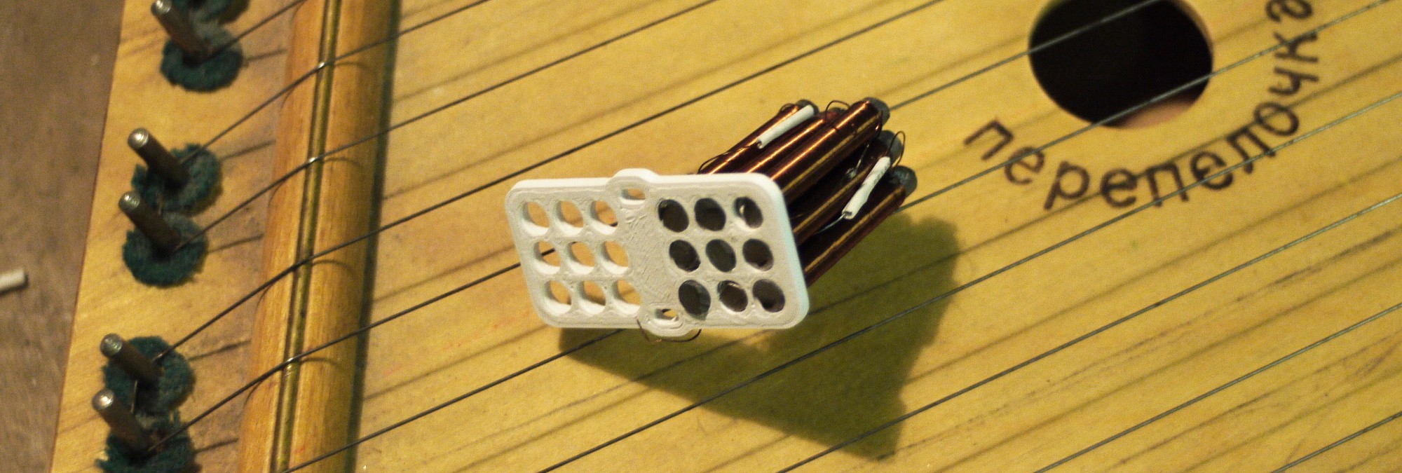
 And I want to say, that it performs very well! Self-proclaimed "modular" electromagnets are pretty small and light, use a little amount of cooper wire and also pretty strong compared to beefy convenient electromagnets, even with nails used as a core material. So I can say, that with nice core material or control circuit, which can sustain powerful magnetic field, it's a win : )
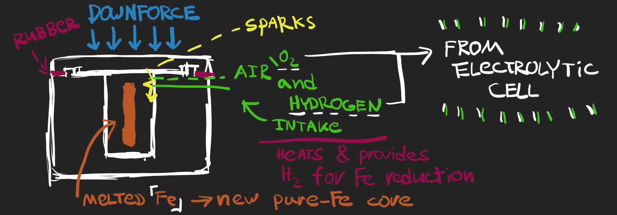 Using H2 intake as a heating element with O2 originally in chamber - it's the most simple solution, which I found, only requires some high-temperature clay, insulator (rubber?) and electrolytic cell.
 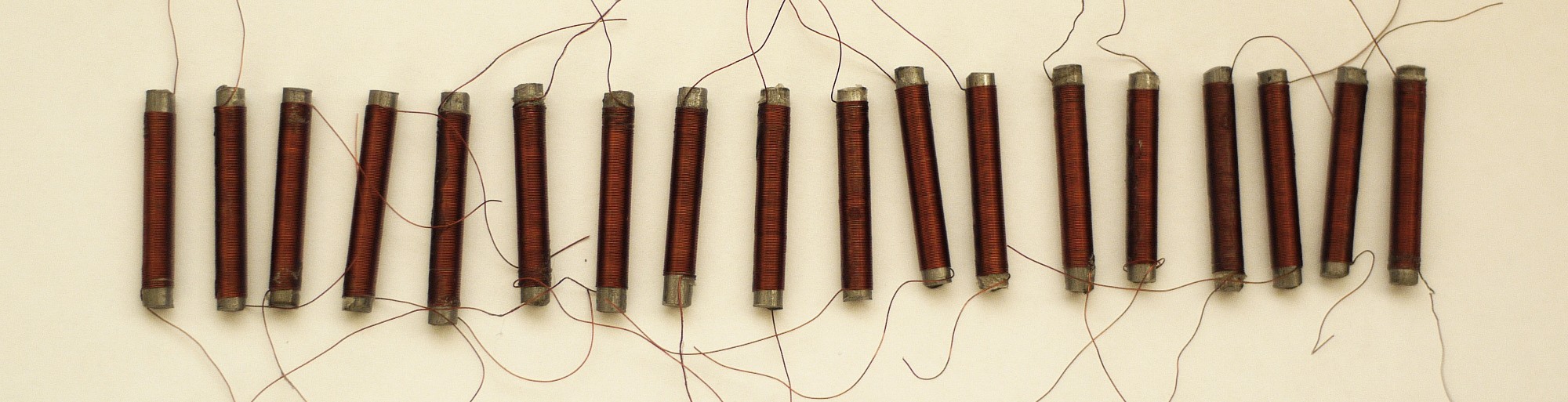 As I'm too lazy to wind them by hands, I had some extreme prototyping experience ->
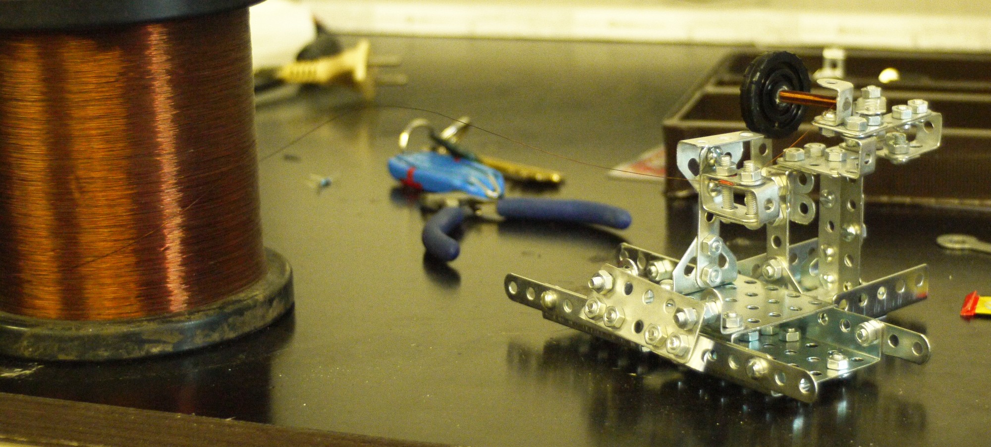 Yeah, it's winding machine made from a building kit! Works surprisingly well!
 This is how schematics looks now. Nothing changed in current monitoring circuit, but now we have IR2117 (or IR2118) MOSFET driver here. What it does - it provides extra voltage over voltage on capacitor C3, so voltage difference between Gate and Source stays positive then needed even then transistor is in high side switching mode. That means, that transistor is fully opened, outputs that needed and dissipates less heat as well, so it wouldn't require hardcore cooling : )
 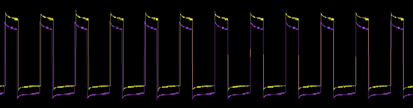 Yellow - control voltage, from logic gates (5V amplitude)
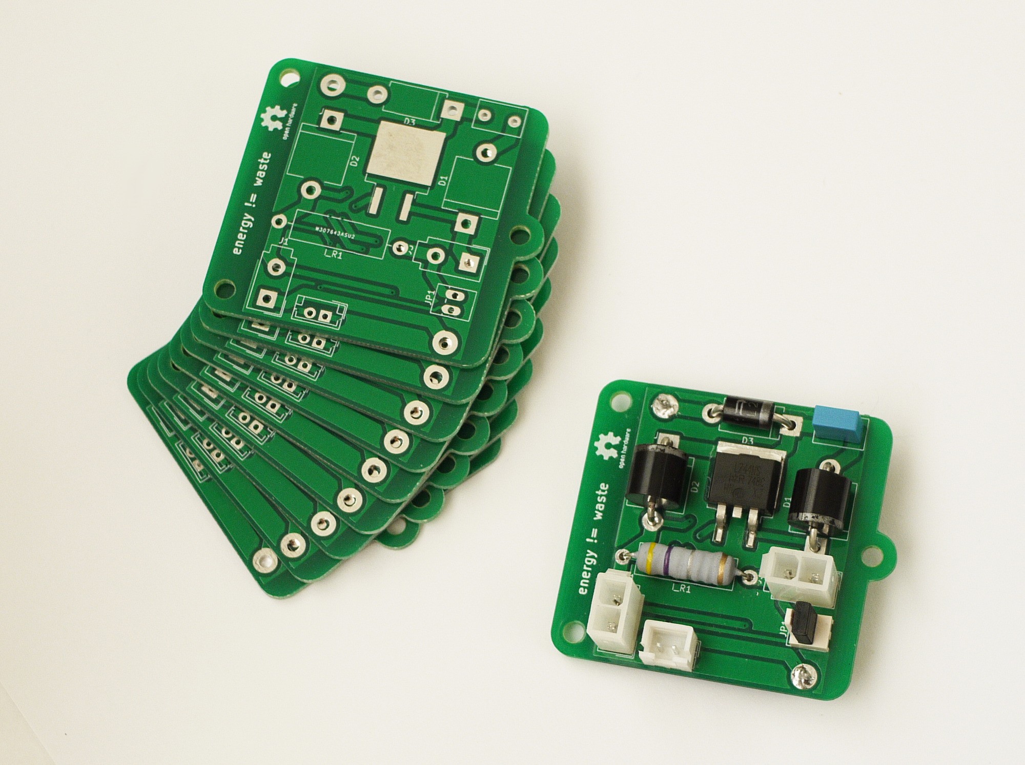
 Well, not that simple! All circuitry, responsible for a giveaway-reserve energy cycle works fine - it generates control signal in right time and then sends it to the gate of MOSFET
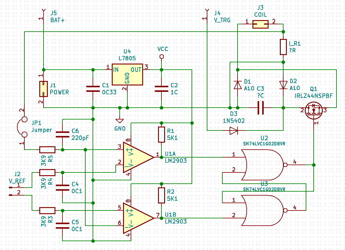 Magical thing! Not unsolvable, anyway : )
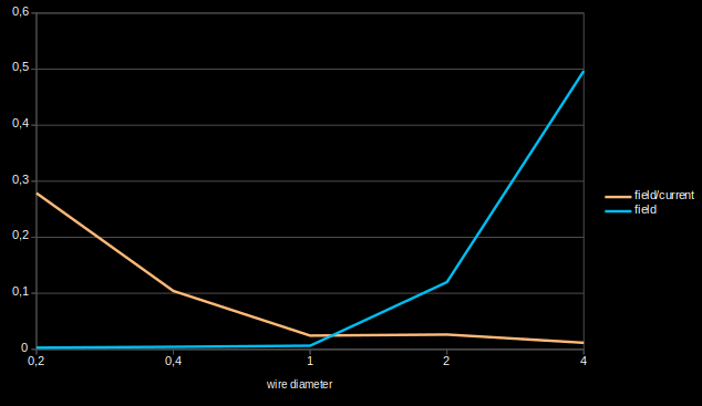 That is very interesting here - how better distribution of area (through which current flows) in case of small wire diameter increases efficiency drastically. Overall, wire is closer to the core and it almost reduces effect of current drop, in case of supplying with the same voltage:
 Looks kinda weird, because it is in-scale and new design is kind of smaller :)
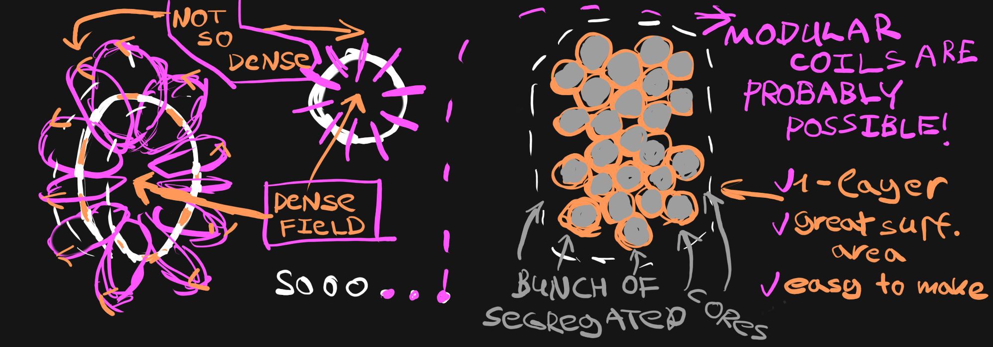 I tried to show it on the left side, you can see one turn of a coil there. Seems logical!
 ^ this picture represents duel with fluid dynamics and glorious victory (thanx, corn syrup!)
 First of all we need to have a look at coil itself. Wire here (along with current) works as a source of electromagnetic field, shown on the left side, and further we place core from wire - weaker field becomes. We need this field to orient magnetic field of our core's material atoms, which works as an "amplifier".
 Also, I want to upgrade coilformer, because it wasn't optimal
 I thought that problem was in viscosity... And it surely was!
 You can see current on coil (reminder: it represents energy of magnetic field), and how boundaries of energy oscillations can be changed with magic of this circuit - here I move lower bound, different runs are coloured differently.
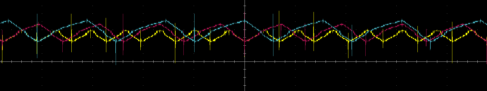 And here I move upper bound, different runs coloured as previously.
 My first reaction after producing new stripes was: "H-o-w?"
 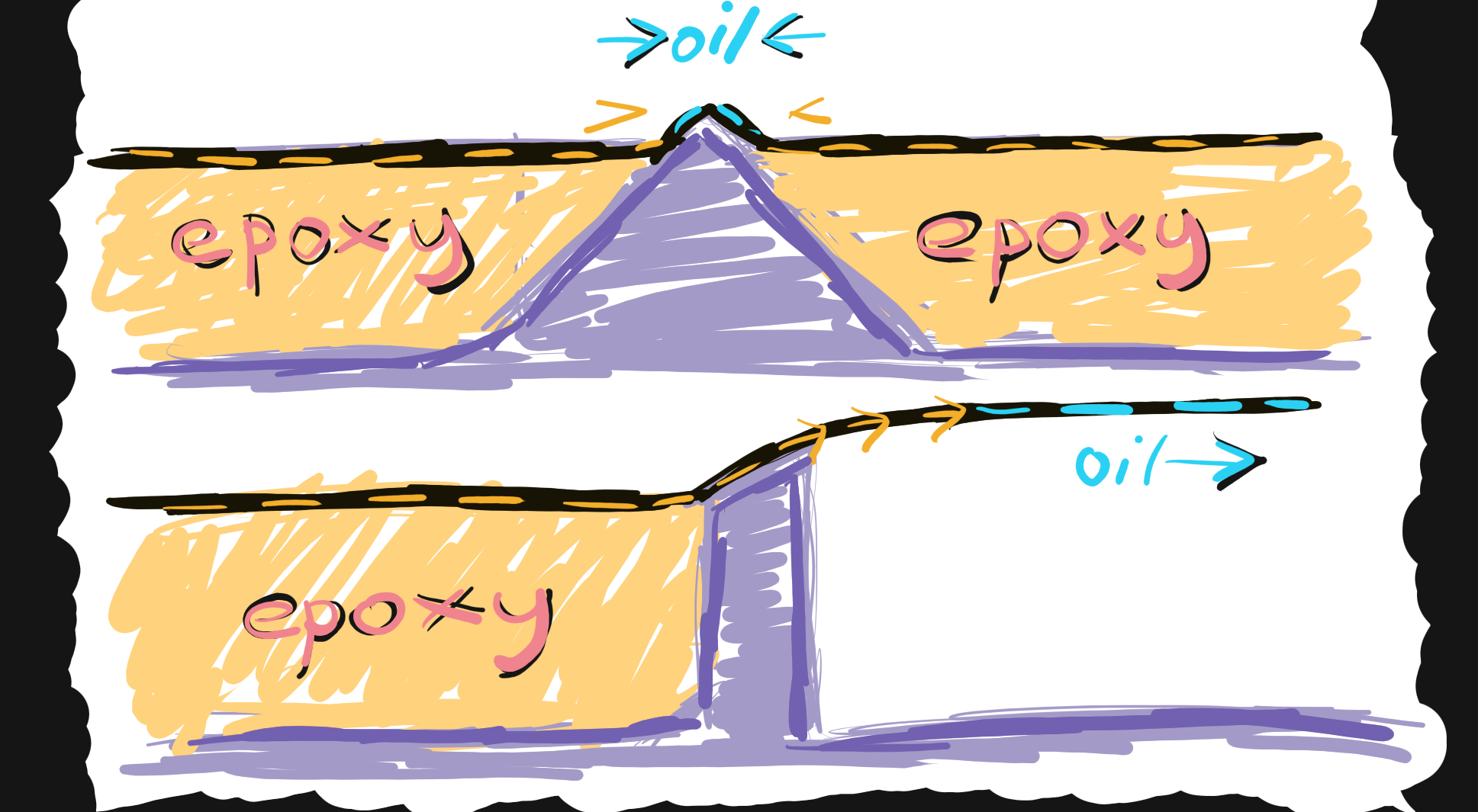 - On top you can see previous structure. Oil stays in place, because it is pushed by epoxy from two sides
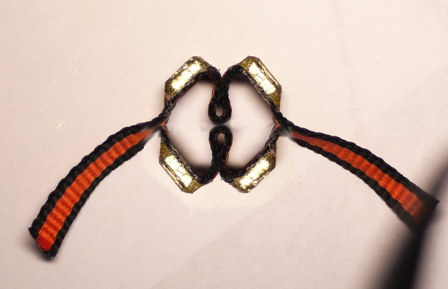 Of course I had only one stripe which bends well, so I mirrored it on this picture, just to show how it would be then contracted. I don't know why, but I like how "geometrically" it looks : )
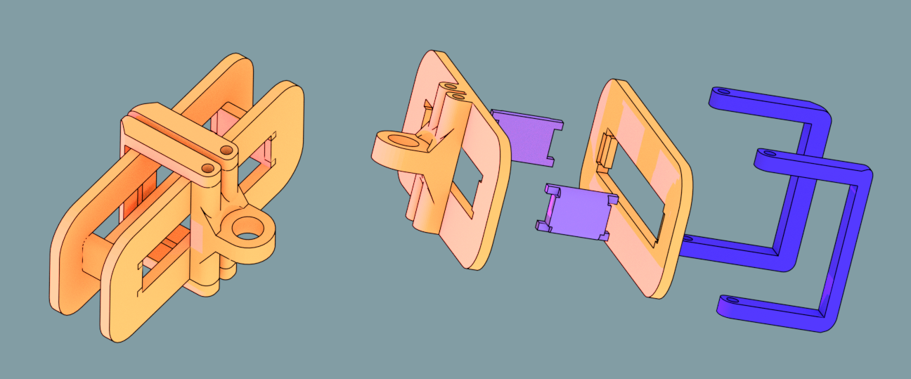 Looks similar to the preview version, now it is sectional to be easily printable. Eager to complete electromagnets part! This is the last step before first test of an actuator. Except mold-fixing, haha
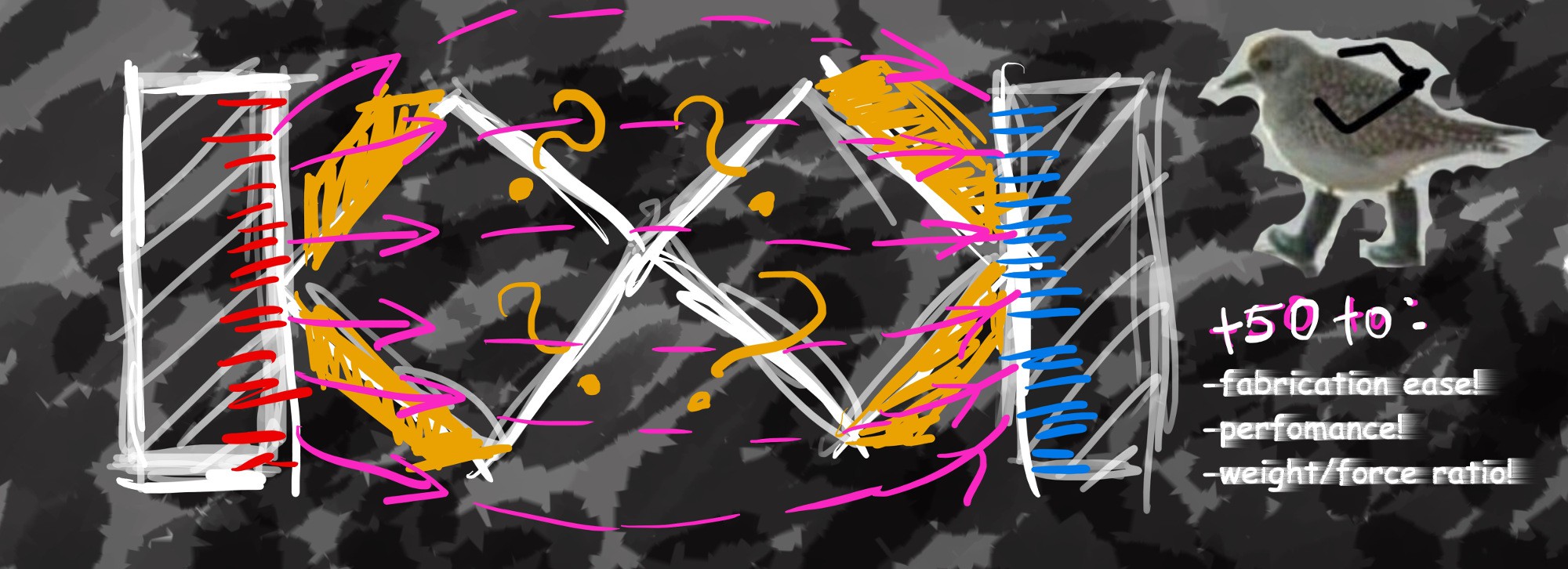 Bird here shows me yesterday, thinking about bending. Bending is quite important part of construction, as it is semi-soft and it's being squeezed along with bending of stripes...
 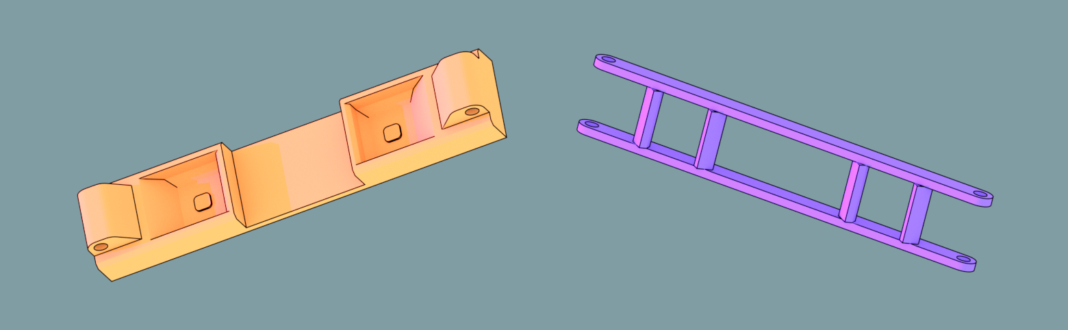 Fun fact - it is also noticeably smaller, so even that requires less material to produce : )