Close
0%
0%

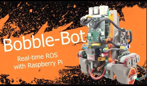
Bobble-Bot

Demonstration robot for learning principles of real-time control using Raspberry Pi, RT Linux, and ROS.

Similar projects worth following
Bobble-Bot is being built to help students, hobbyists, and educators learn about the fundamentals of robotics in a safe, affordable, and fun way. He's a funny looking little guy with a big heart and an ever-present focus on his time critical tasks -- upon which his entire balancing-being depends.

- Supports course work for many classes in computer science and engineering.
- Exercises tailored to a university lab environment are available upon request.
- Comes with a free open-source simulator.
- Customize your Bobble-Bot's software using a C++ or Python API.
- 3D printable parts!

Meet Bobble Bot  


Why did we make this?

We created Bobble-Bot to empower aspiring makers, tinkerers, and creatives. The robot provides a fun and affordable way to acquire and demonstrate valuable skills in computer science and engineering.

What Problem Does it Solve?

Every day businesses around the world struggle to cope with a global shortage in technology related skills and talent. This costs the world economy hundreds of billions of dollars in unrealized revenues.

We believe that one contributor to this problem stems from a lack of accessible, high-quality, and open-source educational material. The Bobble-Bot project helps motivated individuals develop valuable cross-disciplinary technology related skills.

In particular, Bobble-Bot fills a shortage within the educational robotics space. Until now, there has not been an easily accessible open-source example of real-time control for the DIY crowd. 

What Are Our Goals?

We want educators, students, and hobbyists to get up and running with this open-source robot as quickly as possible. Our hope is that this project functions as a guide for how to develop and test robust control systems for robot prototypes. We envision this robot will be useful to professionals looking to sharpen their skills while having fun, and also to students looking for a hands-on application to the often dry engineering theory covered in courses around the world. The combination of simulation and hardware opens up many possibilities for exploration and development.

Where to Start

We recommend you start with the Bobble-Sim. That's a free way to gain some quick insight into the project.

How to Contribute

For software contributions, please read our contributing guide. We welcome support in all areas, though. If you have any ideas, leave a comment. Thanks!

Licensing Information

Bobble-Bot's simulation software licensing agreement can be found here.
The robot's software infrastructure heavily leverages the Robot Operating System (ROS). The ROS licensing agreement can be found here

The simulator also relies on Gazebo. The Gazebo licensing agreement can be found here.

BB2_BoM.xlsx

BB2 Bill of Materials

sheet - 38.91 kB - 09/29/2019 at 18:47

Download

Bobble-Bot Assembly.pdf

Assembly Instructions and Exploded views

Adobe Portable Document Format - 674.21 kB - 09/29/2019 at 18:16

Preview

BobbleBotCableHarnesses.pdf

Document detailing how to fabricate the cable harnesses needed to make a Bobble-Bot.

Adobe Portable Document Format - 222.83 kB - 09/29/2019 at 17:56

Preview

WheelDynamics.png

Reference equations of motion for wheel dynamics

Portable Network Graphics (PNG) - 81.84 kB - 04/16/2019 at 02:29

Preview

PendulumDynamics.png

Reference equations of motion for pendulum dynamics

Portable Network Graphics (PNG) - 120.47 kB - 04/16/2019 at 02:29

Preview

View all 19 files

  • 1 × Raspberry Pi Model 3B Linux SoC. Runs our balance controller and other Bobble-Bot software
  • 2 × Turnigy Multistar 4822-690vK 22 Pole BLDC motors Brushless DC motors that drive the wheels
  • 31 × 91502A101 McMaster-Carr M3 x 0.5, 5mm LNG
  • 6 × 91290A100 McMaster-Carr M2.5 x 0.45, 5mm LNG
  • 2 × BB2S001 BB2 Fender/Encoder Mount - 3D Printed

View all 40 components

  • Bobble-Bot Joins Hacktoberfest

    Mike Moore10/04/2020 at 18:59 0 comments

    I don't know about everyone else, but October is my favorite month of the year! It has finally started to cool off in South Texas. We've had some amazing weather days lately. Despite all that, of course, I'm still inside more than I should be (damn you COVID). So I find myself cruising around on the internet, when all of a sudden, I spot something that immediately made me think of Bobble-Bot... 

    And it's another great reason to love October! Hacktoberfest 2020

    Caught up in the spirit of October and open-source software, I decided to write up some issues and submit them to our project's GitHub. If you're interested in contributing to the Bobble-Bot software stack, now's your chance! 

    In my opinion, the computer vision and navigation related issues would make for a pretty fun hobby project for those looking to learn or get practice in ROS.

    ezgif com-gif-maker
     Here's to happy hacking with Bobble-Bot in October!

  • Build a Bobble-Bot

    JSook09/28/2019 at 22:08 0 comments

    Robots can be complicated, everyone knows that. Bobble-bot is design to be as simple as possible. It only takes a few tools to assemble the robot - a 2.5mm allen wrench, a 2.0mm allen allen wrench, and something to cut zip-tie tails. Easy-peasy! 

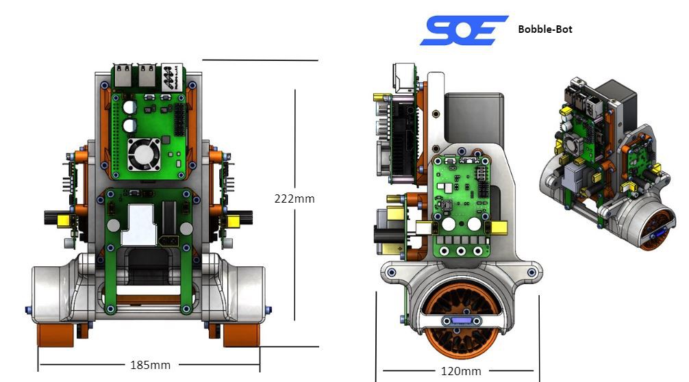
    Hopefully you've seen the Bobble-Bot assembly video in a previous post. It only took about 30 minutes to take a whole bot from loose components to fully bobbling. The robot itself is small, light-weight, and easy to handle. About 185mm x 222mm x 120mm without extra peripherals, roughly 3lbs. 

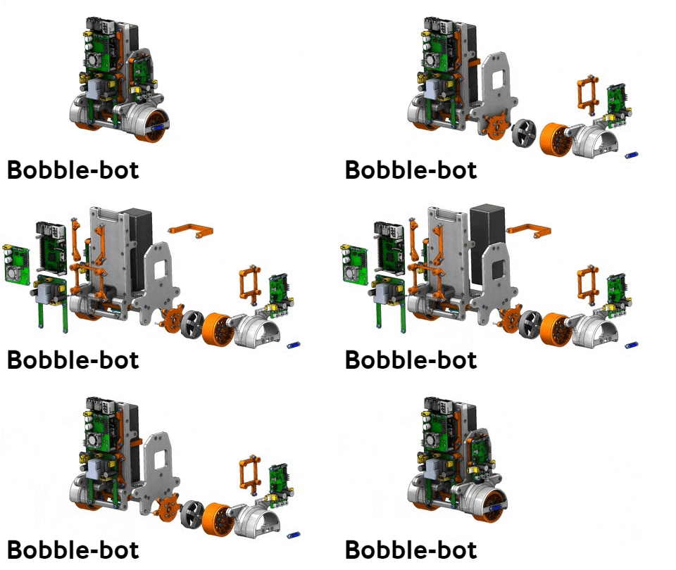
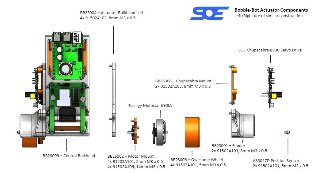
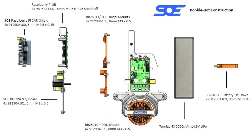
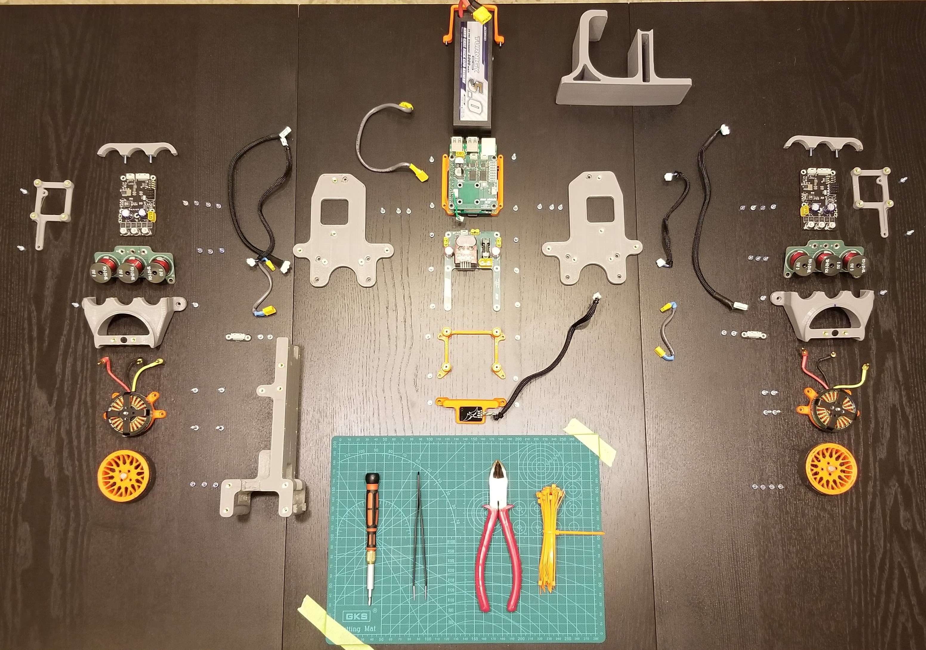
    The robot is easily split into three sections. The right actuator, left actuator, and center section. The Actuators are nearly identical save for a couple mirrored components. It takes eight unique parts and a handful of screws to assemble each actuator. The two actuators are then easily bolted to the Central Bulkhead of the robot, P/N BS2S009. 

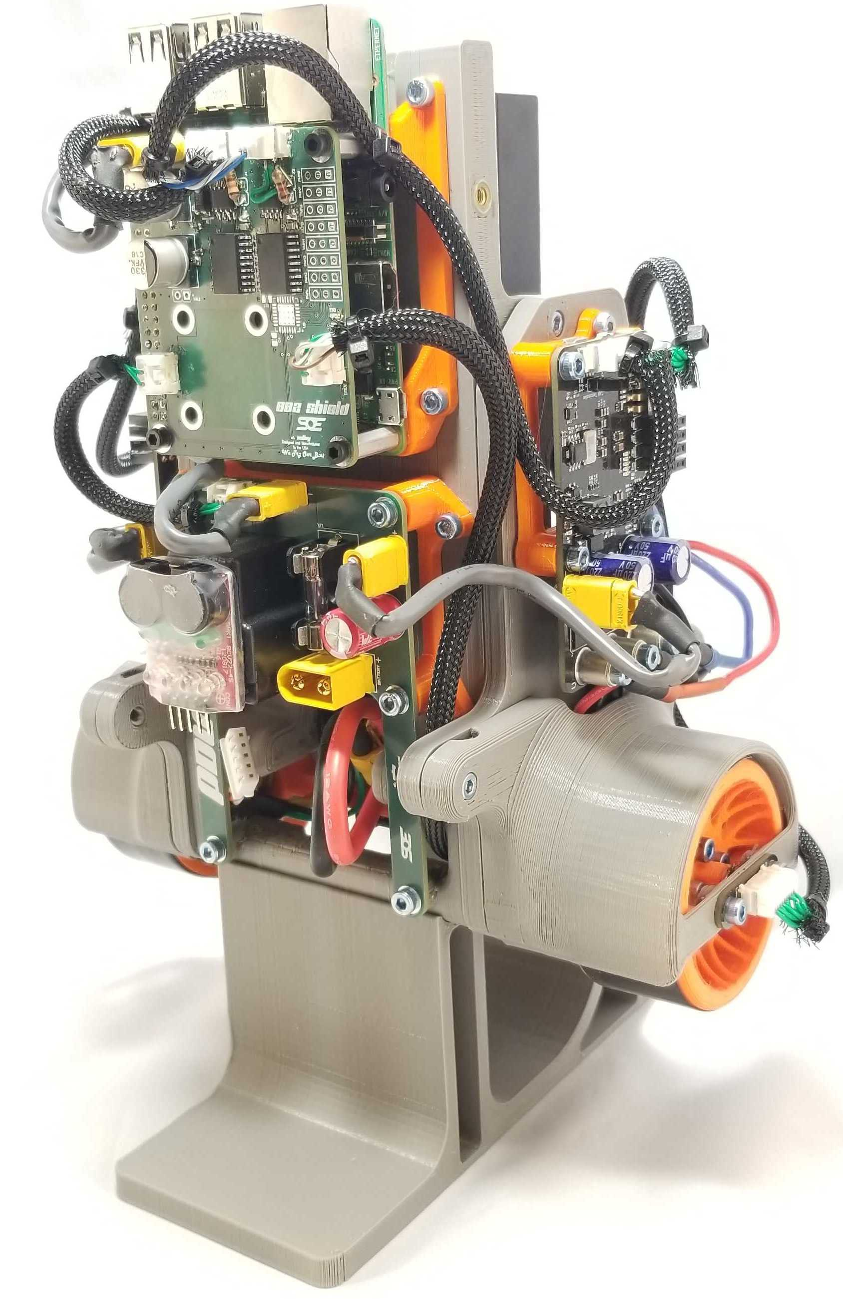
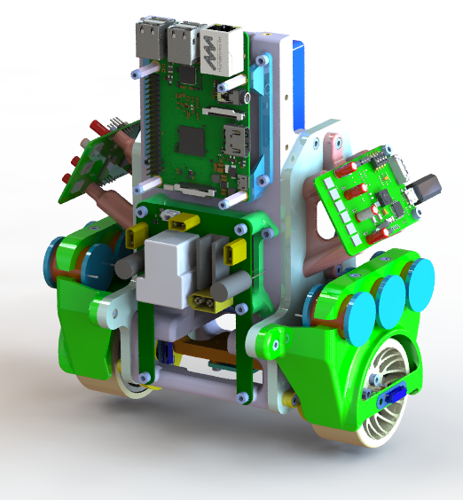
    The center section of the robot secures the Raspberry Pi 3B, with the SOE developed CAN shield, and SOE developed Power Distribution Unit (PDU), and the battery. The Bobble-Bot has unique mounts for each of these components. 

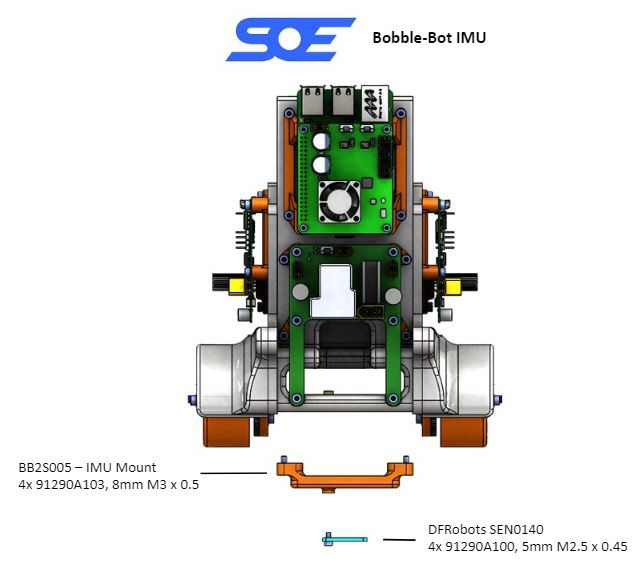
    The last component to be attached is the DFRobot SEN0140 10 Axis Inertial Measurement Unit (IMU). The IMU is mounted between the wheels, aligned with the axis of rotation of the wheels themselves. This mounting configuration minimizes the complexity of transformations required to get useful data from the sensor. 

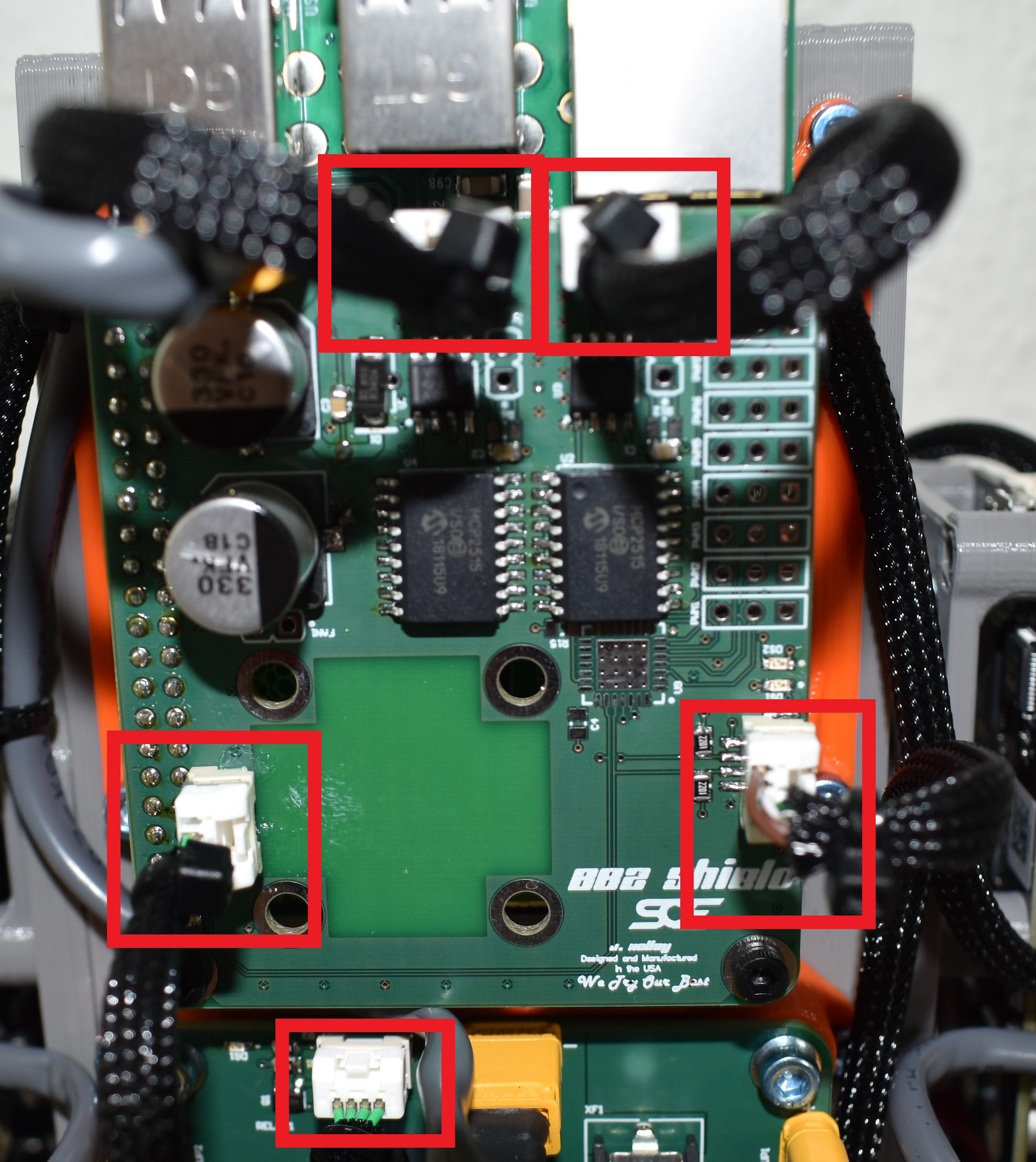
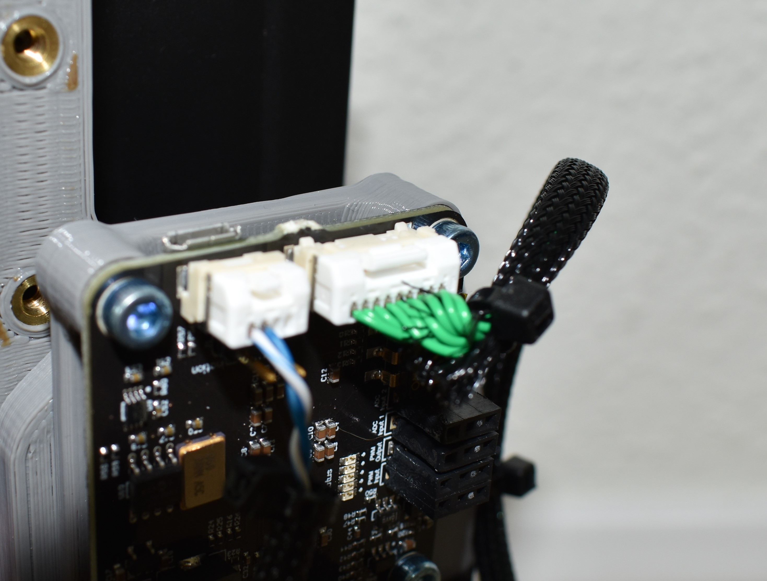
    To complete the assembly of the bot, a few cables are required. Each Chupacabra Servo Drive requires a power connection from the PDU as well as a CAN connection to the Raspberry Pi. Each wheel has a magnetic encoder that is connected directly to its Chupacabra. The Raspberry Pi gets a power connection from the PDU and a CAN signal to trigger the PDU's safety circuit. Finally, the IMU is connected to the Raspberry Pi's GPIO pins. 

    That's it! Being geared toward students, Bobble-Bot is intended to be completely customizable. All, and I mean all, of the structural components are 3D printed. The Bobble-Bot also has 6 threaded inserts on the top half of the robot that can be used for any custom peripherals you can dream up. The Raspberry Pi has ample GPIO availability, four USB ports, and an ethernet port all ready to be exploited to your robotic delight. 

    This is Bobble-bot - What will you build?

    - Josh

  • Look Ma, no inductors!

    James Holley09/27/2019 at 23:49 1 comment

    Hello everyone, it's time to address the elephant in the room... or on the sides of Bobble-Bot.

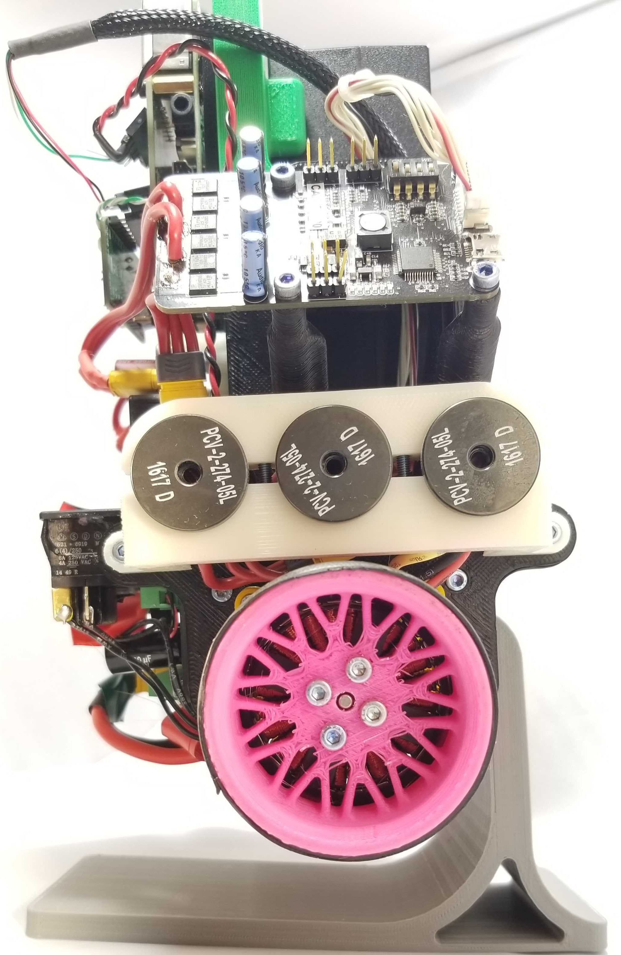
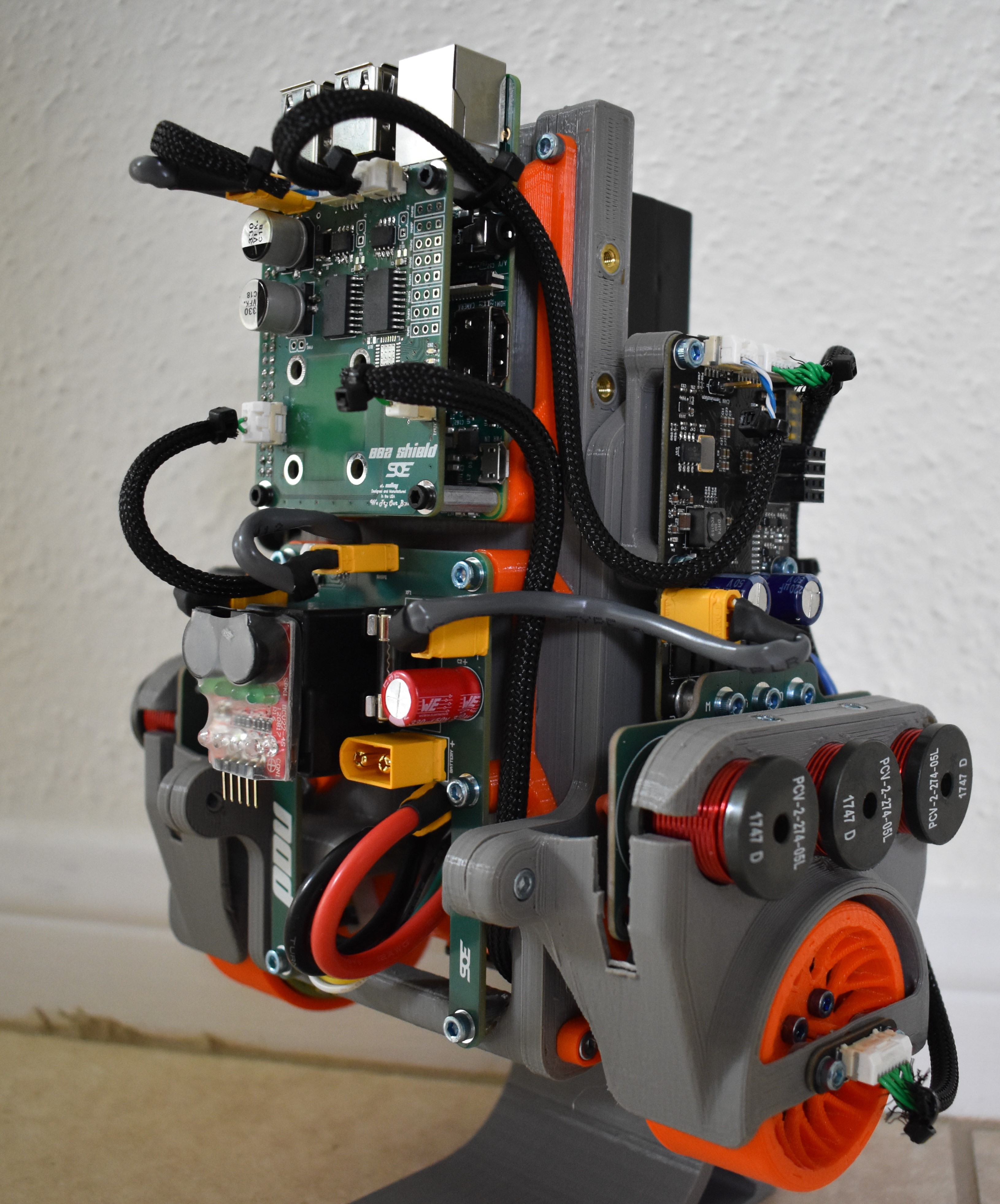
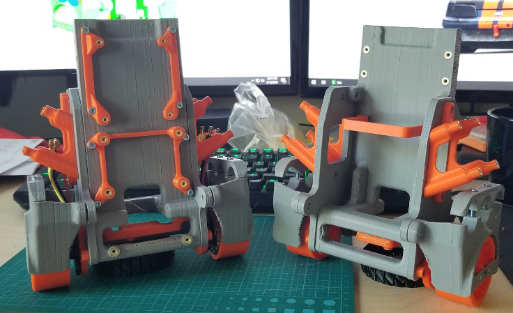
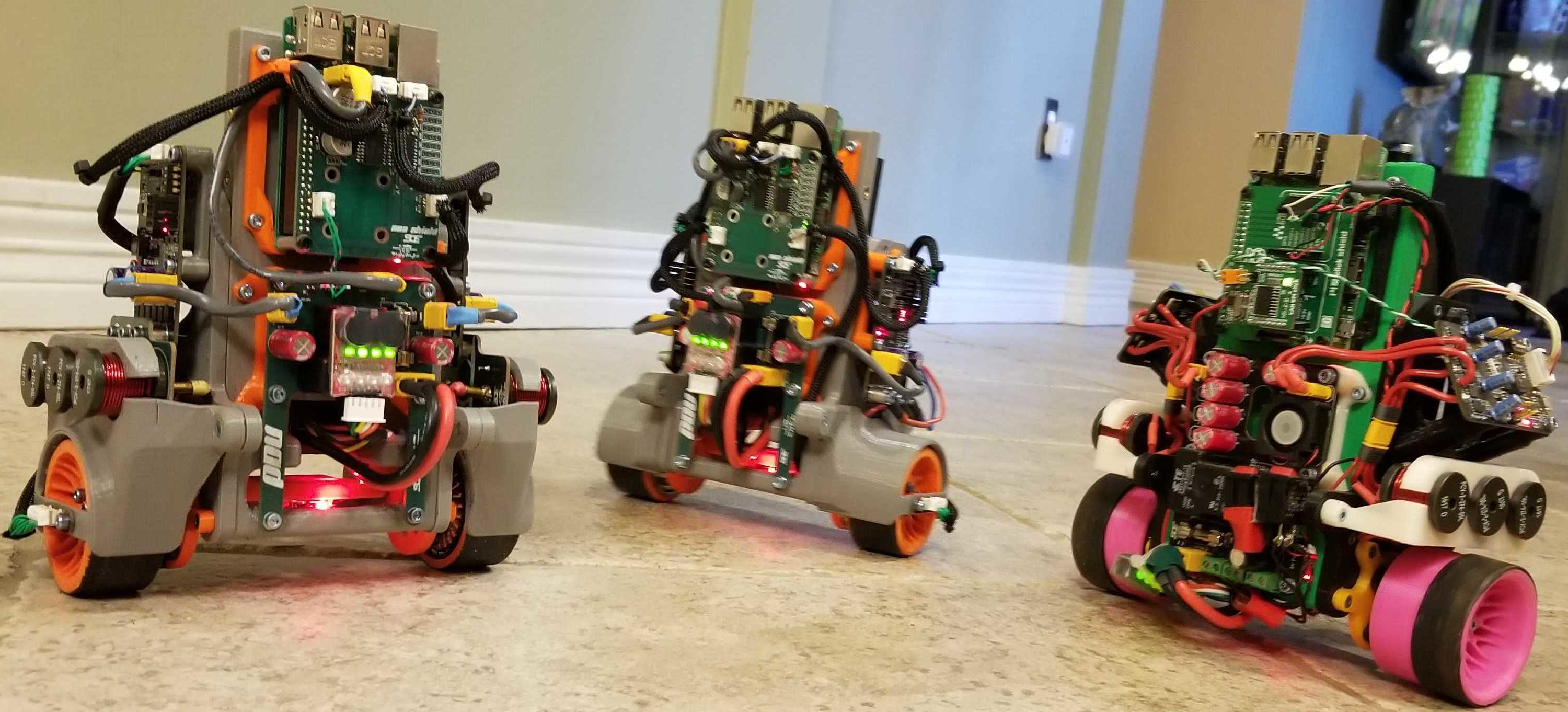
    We've fielded questions about our inductors for a while now, and the short story is, we don't need them!  Here's a picture of the old Bobble-Bot with inductors and a picture of updated Bobble-Bot with some slimmed down sides.

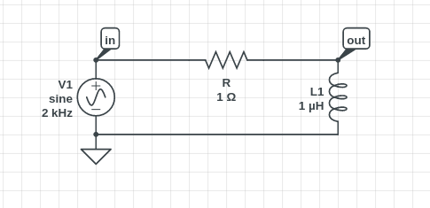
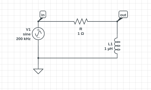
    For those of you that are always looking for more details, here's the full scoop.  Bobble-bot includes custom motor controller boards that allow us to interface with hobby motors, yet still perform servo control.  That is, we're using BLDC (brushless direct current) hobby motors to keep the price down - motors that are usually used on quadcopters or RC planes - and adding a sensor and motor controller board that allows us to do fine motor control so we can stay balanced.  Servo control of these types of motors is hard because the motors are really small and don't have a lot of inductance themselves.  This makes current control (and therefore servo control) difficult.  Consider the following circuit (from circuitlab.com where you can do some free online circuit simulations):

    What we're trying to do here is understand how we can regulate current through L1.  In a BLDC motor, current maps to torque, and this is especially true at stall conditions, so regulating or controlling current allows the control of motor torque.  The resistance here is small - wires are hooked up directly to the motor, and the inductance here is also small.  Note that these parameters will change depending on what kind of motor you use and the size and gauge of the wires you are using to hook up to it.  For our purposes today explaining the purpose of the inductors, I've just chosen some general numbers that are easy to see what is going on.  

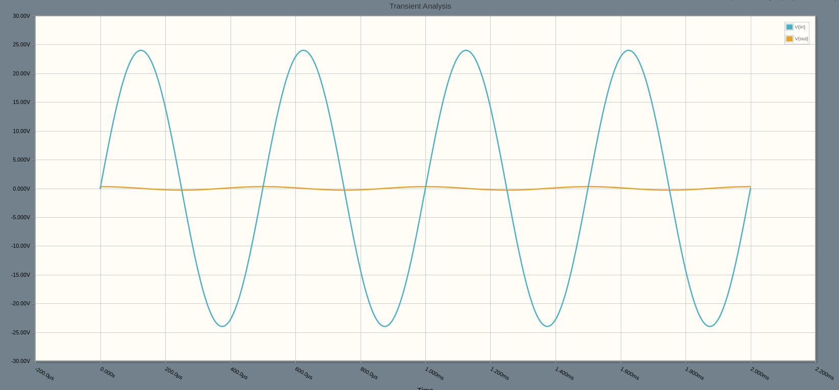
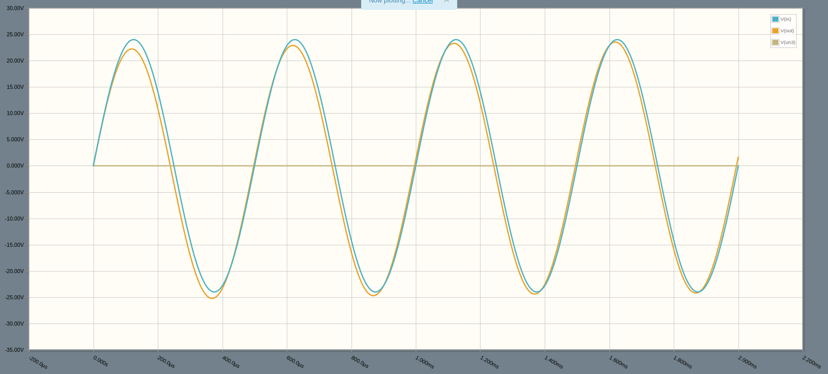
    If you run a time domain simulation on this circuit, you will see the following:

    Here you see that there's almost no output voltage across the inductor.  The current of an inductor is the change in voltage over time, so what you end up getting is small voltage change, and therefore a small amount of current.  Let's see what happens if we add some more inductance to our circuit.

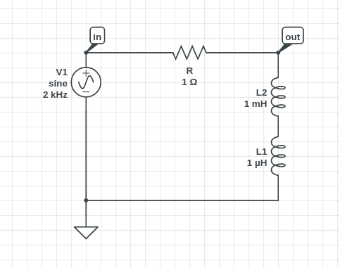
    What I've done here is added our inductors to the side of the robot - big inductors are the training wheels for current control, let's take a look at the effect.

    And... BOOM - we've got what we wanted - we now have more output voltage across our motor, but unfortunately, we've done so at the expense of some big pieces of metal attached to the side of the robot.

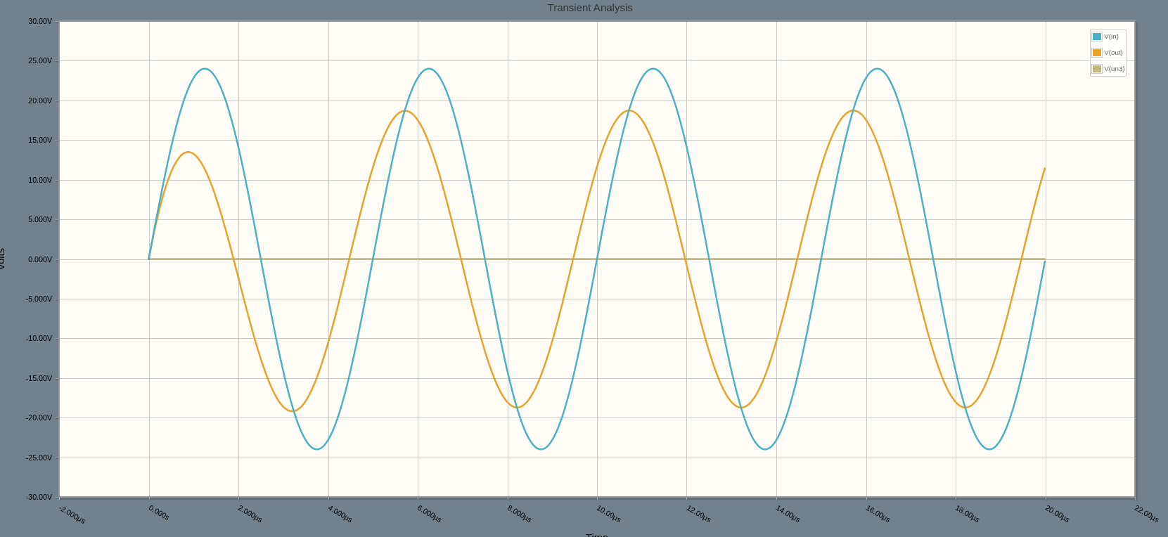
    So what next?  How do we get rid of them?  The next step is to remove the inductors, but then increase the frequency at which we are commanding our motors - this is done by increasing the frequency of the voltage source pictured on the left side of the diagram, or in Bobble-Bot's case, increasing the PWM frequency and control loop frequency of our motor controller.  Here's what that circuit looks like:

    And the response:

    You can see that we are getting voltage across our inductor again, and that allows current control to be back in the picture for the original circuit.

    By putting in some work and speeding up the control algorithm on our motor control boards, we were able to achieve the current control that gave us enough performance to stay balanced without needing the inductors.  This also translates into power savings, faster motor response, and faster overall speed from our motors.  

    And of course, what blog post is complete without a video!?  Enjoy!

  • The Making of Bobble-Bot

    Mike Moore08/22/2019 at 03:24 0 comments

    We are happy to announce that we have now successfully made three Bobble-Bots, and all are working great! Here's a behind the scenes look at our current "assembly process" (one Josh).

    A follow on post will contain a more detailed write-up with pictures from the process. Check back soon!

    Looking for Help

    In order to meet customer requests, we're now actively looking to expand the Bobble-Bot team. Please contact us if you would like to contribute as a consultant doing graphic design and/or technical writing. Familiarity with ROS would be a huge plus. Thanks!

  • Using Matlab for Object Tracking

    Mike Moore07/03/2019 at 17:37 0 comments

    Recently I received some feedback from a few of our users requesting a Matlab sample project that can communicate with Bobble-Bot. This seemed like a reasonable enough request, so I released a new Matlab interface for Bobble-Bot last night. I'm thankful for the feedback, and excited to provide the capability to our users. Keep the requests coming. We'll do what we can!
    If you're unfamiliar, Matlab and its sister software package, Simulink, are engineering applications that combine textual and graphical programming to facilitate model based design. Both packages are commonly used in engineering curriculum around the globe. Together they provide a huge ecosystem of supporting software packages that facilitate design and analysis. Both are often used within robotics educational curriculum. The Bobble-Bot Matlab interface will allow for students already familiar with Matlab to get up and running with Bobble-Bot quickly.

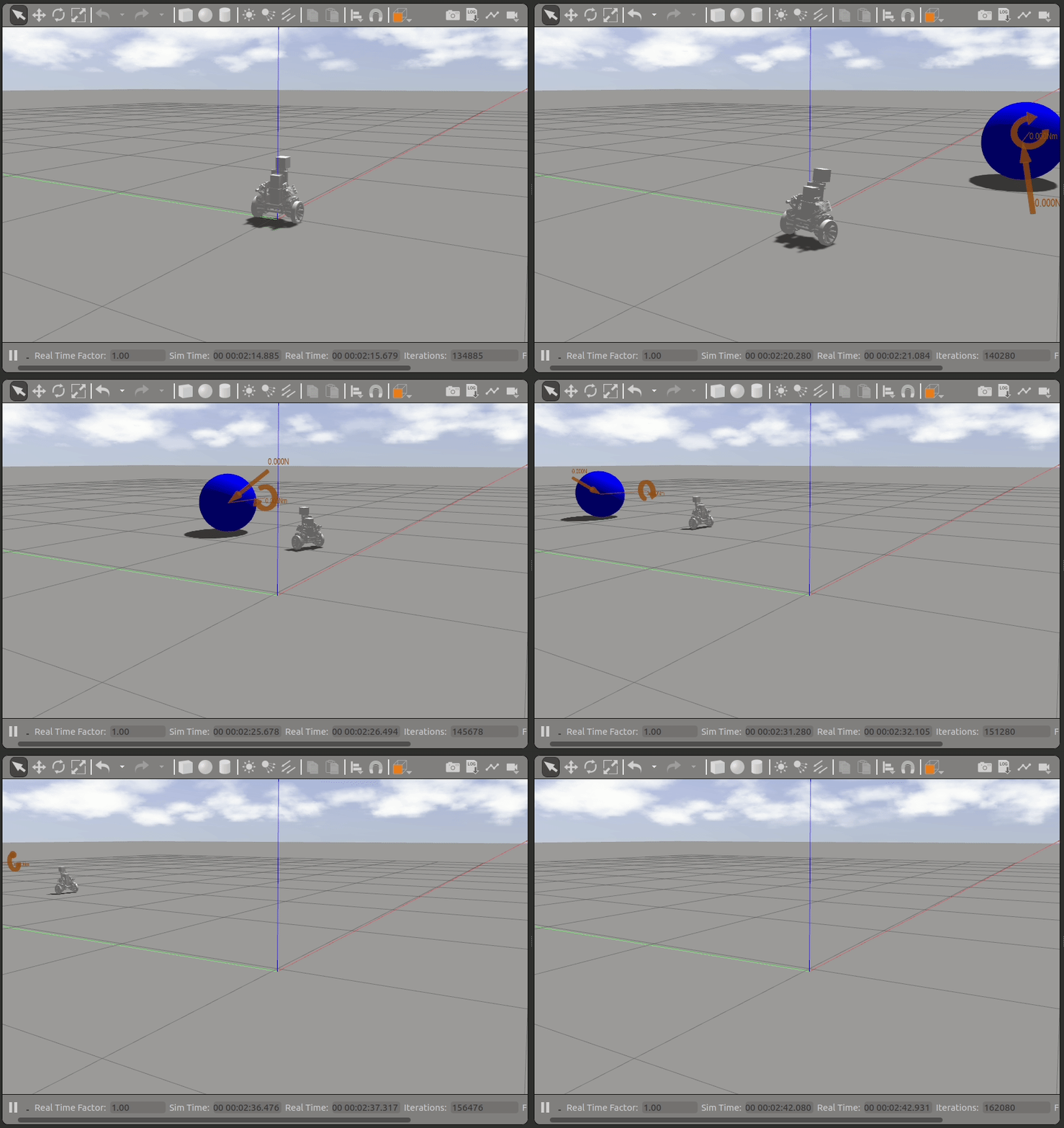
    This post will give some more information on the integration of Matlab and Bobble-Bot. I will work through one example use case and provide links on how to get started on your own. See the graphic above to understand where we're headed. By the end of this post, you'll be able to teach Bobble-Bot to seek for and follow a blue ball using Matlab in combination with techniques from image processing. The source code for the demonstration project can be found here. Keep in mind, this is just a jumping off point. Once you have Matlab talking to Bobble-Bot, a whole world of possibilities opens up. You'll have the full power of the Matlab engine at your disposal! Enough hype... let's just get started and see how this actually works.

    Get the Software You'll Need

    This example is adaptable for both simulation and real hardware. This post will focus on simulation in order to make it easier for others to follow along. That said, the first step is to make sure you have the Bobble-Bot simulator. Go grab it for free from GitHub. Follow the instructions on the README to get going. More detail can also be found in this blog post.

    Next up, you'll need Matlab and the Image Processing and Robotics System Toolboxes. If you're a student, check with your university to see if you can get a copy of Matlab and these toolboxes for free. If you're in industry, be prepared to shell out some dough if you do not already have these available to you. Such is the way of the Matlab.

    Finally, clone this additional repository in order to get the custom Bobble-Bot ROS message interface for Matlab along with the ball following example.

    git clone https://github.com/super-owesome/bobble_matlab.git

    Add Camera Sensor to Bobble-Bot URDF

    Now we'll need to modify the URDF in bobble_description to add a camera sensor and plugin to the Gazebo simulation. This will enable Matlab to see the environment via a ROS camera message topic. To do this, un-comment the following line in bobble.urdf.xacro so that section looks like so:

    <xacro:include filename="$(find bobble_description)/xacro/bobble_chassis.urdf.xacro" />
    <xacro:include filename="$(find bobble_description)/xacro/camera.urdf.xacro" />
    <xacro:include filename="$(find bobble_description)/xacro/bno055_imu.urdf.xacro" />

    Be sure to re-build the simulation after making this change using catkin build.

    Load the Bobble-Bot ROS Messages into Matlab

    Let's make sure we can use Matlab to communicate with the Bobble-Bot sim. Start by launching the sim with the following command:

    roslaunch bobble_controllers run_sim.launch

    Next, launch Matlab and navigate to your bobble_matlab folder. Call the LoadBobbleMessages function to load the custom Bobble-Bot ROS messages into your path. This is a one time operation. From there, you can initialize the Bobble-Bot simulation connection and test sending some commands like so:

    >> LoadBobbleMessages();
    ...
    Read more »

  • Get Real(time)

    James Holley06/23/2019 at 20:04 0 comments

    One of the coolest features of Bobble Bot's software is the realtime kernel running on the Raspberry Pi.  Admitting that I think the realtime kernel is 'cool' just shot me up in the rankings of "Most Likely to Get a Wedgie in the Near Future," but whatever, I'm going to tell you about it anyway.

    In the controls world, timing and speed are everything.  Jitter is the deviation from true periodicity of a periodic signal, or in layman's terms, the difference in time of when you expect your control loop to execute, and the actual time it does.  This has been studied extensively and leads to a conclusion we all knew was coming - if your control loop doesn't execute consistently, there are going to be problems.  

    When we get asked about Bobble Bot and the control system, a lot of times people ask "Why didn't you use a microcontroller?"  This is an excellent question - microcontrollers are built to execute control loops at a given rate- no operating system, deterministic servicing of interrupts and quick writes to communication ports or GPIO.  This minimizes the effort you have to go through to mitigate problems with jitter.  However, microcontrollers have limited functionality and a steeper learning curve for developers.  The Raspberry Pi was designed to "put the power of computing and digital making into the hands of people all over the world" - in layman's terms again, it's a really accessible cheap computer for teaching programming to people.  So, we thought it would be super owesome if we could merge both worlds - give control loop access to people via the Raspberry Pi so they are able to work on and experiment with control systems that have demanding requirements.  To make this happen, we chose the Raspberry Pi + Realtime Linux Kernel.

    The realtime kernel for Linux is becoming more popular and is working its way into the mainline development.  Better yet, a group of developers have integrated the RT patches into the Raspbian 4.14-y kernel.  I was also happy to find another hackaday project dedicated to testing this kernel!  Building the kernel is documented here, with the only notable exception for the version we are using for Bobble Bot is setting CONFIG_HZ_1000=y and CONFIG_HZ=1000, which increases the scheduler base frequency (click here for more details on the scheduler if you want them).

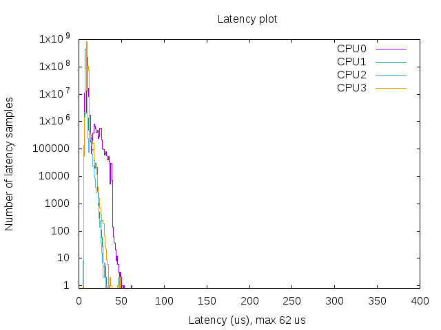
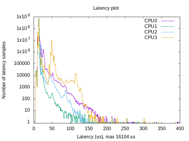
    RT-Tests were then used to test the latency of the realtime kernel (bottom) against the standard kernel (top).  

    These charts make it pretty clear - if you want to make sure a thread is executed at a consistent rate, you are going to need the realtime kernel.  Also, the latency of the regular kernel exceeded 16 ms at one point - for an unstable system like Bobble Bot, this could cause a fall.

    Even though these charts do a pretty good job of illustrating what you get with the RT Kernel, I wanted to provide another example you can test on your own.  This is just a small piece of C++ code that toggles a pin on the Raspberry Pi in a RT thread.  DISCLAIMER: This is just a bit of test code.  I think using delays and iostreams in a RT thread is usually bad practice, but for the sake of getting a little program off the ground, we're doing it anyway.

    gpio-rt-test.c

    #include <pthread.h>
    #include <sys/mman.h>
    #include <wiringPi.h>
    #include <iostream>
    
    int main(int argc, char **argv)
    {
      struct sched_param param;
    
      // Using GPIO pin 21 - feel free to use whatever is convenient for the test
      const unsigned int GPIO_PIN = 21;
    
      // Comment out the section below to remove RT scheduling
      param.sched_priority=sched_get_priority_max(SCHED_FIFO);
      if(sched_setscheduler(0,SCHED_FIFO,¶m) == -1){
        std::cout << ">>> Failed to schedule RT thread." << std::endl;
        return -1;
      }
      if(mlockall(MCL_CURRENT|MCL_FUTURE) == -1) {
        std::cout << ">>> Failed to lock memory." << std::endl;
        return -1;
      }
      // End of section to comment out for RT scheduling
    
     wiringPiSetup();
    ...
    Read more »

  • Mike's Software is Broke...Again!

    Mike Moore05/26/2019 at 21:35 0 comments

    The only excuse I have left

     Why test when James breaks everything anyway?

    Developing software for a complex embedded system is hard. Tracking down a single bug in such a system can often take hours. Even worse, "fixing" a bug in one of these systems often uncovers another bug. It is a vicious cycle that embedded software developers unfortunately know all too well. Time spent resolving these issues during the development of a new product is costly. Many projects fail as a result of brittle and inadequately tested software. Many more succeed, but only after pouring a tremendous amount of money and resources into solving these issues. Fortunately, there are free and open-source tools that can be used to help avoid these problems. This project log will show the approach taken for developing and testing Bobble-Bot's embedded software.  

    There's no excuse for your sloppy code, Mike

    Software folks are quickly running out of viable excuses for buggy and un-testable code. I'm personally sick of uttering the phrase "but...it worked on my machine".  Many free and open-source tools are now available that can help developers create and maintain a set of automated tests of their code. Here's the list of tools that we use for testing Bobble-Bot's software (all are free).

    Testing Bobble-Bot Software

    One of the main design goals for Bobble-Bot was to open up the software development process to the open-source community. This facilitates collaboration and learning, but it also introduces some risk. How can we ensure that our software continues to work as developers from around the world make contributions? Fortunately, this is a problem that has been solved many times over by the open-source software community. To mitigate the risk, we simply stand on the shoulders of giants. Bobble-Bot, like many other open-source projects, relies on an automated testing and continuous integration pipeline in order to ensure that our software remains in a working state.

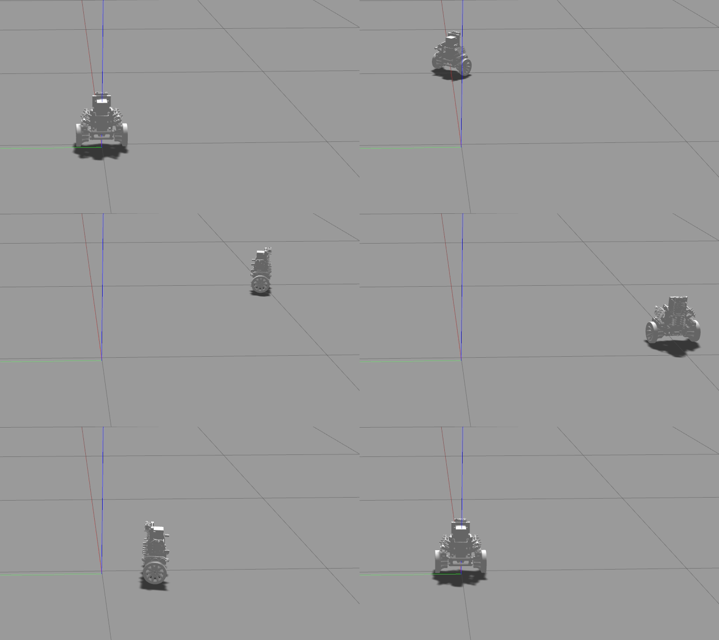
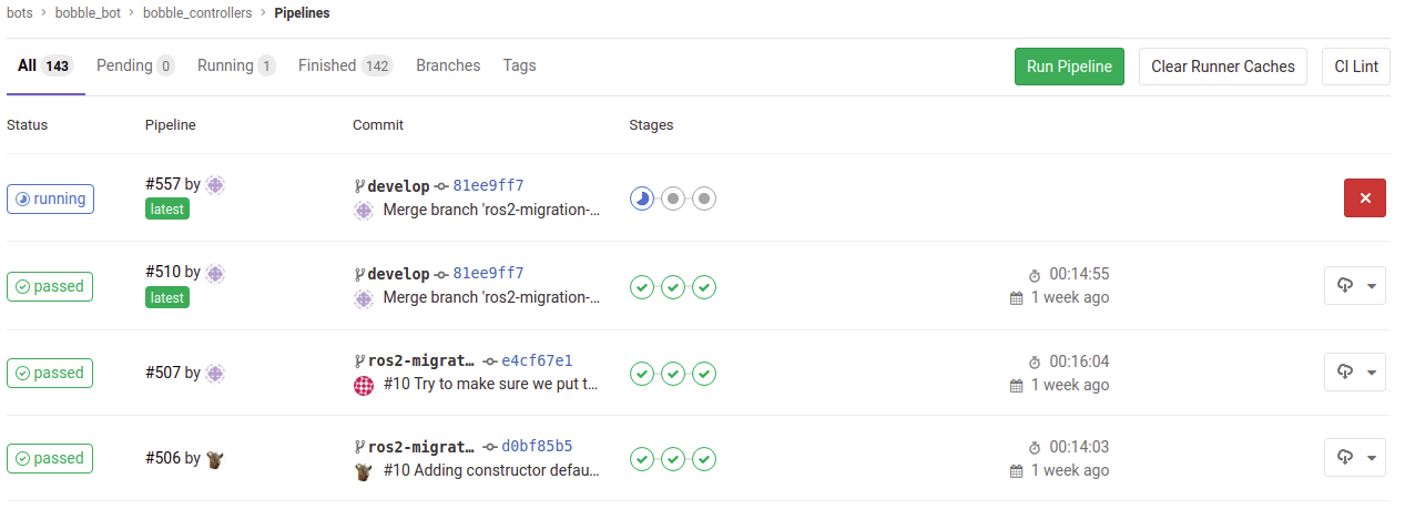
    What this all means is that every time a change is submitted to our project's GitHub repository, an automated build and testing pipeline is triggered. This testing pipeline is comprised of stages which build, test, and analyze the proposed changes. The picture above is a view of the pipeline in action. The testing stage includes eighteen different pass/fail checks that are performed on the balance controller using our simulator. The analyze stage produces a summary Jupyter notebook which is automatically uploaded to our build server as the final and primary output of the testing pipeline. This notebook is a document that is manually reviewed before accepting the proposed software changes to our development baseline. The table below describes the tests that are done and provides links to the actual source code for each test.

    Bobble-Bot's automated tests

    Test NameDescriptionSource Code
    No balanceBobble-Bot uncontrolledno_balance.test
    Impulse forceBalance control active, impulse appliedimpulse_force.test
    Balance controlBalance control active, drive aroundbalance_controller.test
    Drive squareBalance control active, drive in squarejs_drive_square.test

    Testing With Simulation

    Simulation can be an invaluable tool for automated testing. For Bobble-Bot, we use Gazebo as our simulation environment of choice. Gazebo was selected because it is free and it integrates well with ROS. Of course, in order for your test results to be trustworthy, your simulation must adequately approximate reality. Check out this post where we establish the validity of the Bobble-Bot...

    Read more »

  • Bobble Build: Part 2 - Crimpin' ain't Easy

    James Holley05/19/2019 at 21:33 1 comment

    Is crimpin' easy?  Hell yeah!

    Making cables is the WORST part of finishing a build.  We've all been there - adding the final touches to a project just to find out that some (or all) of the cables have a loose connection, bad crimp / solder, wrong pinout, etc.  Sometimes pins push back out of their connectors or, as you are trying to solder a pin, you melt the whole thing...  

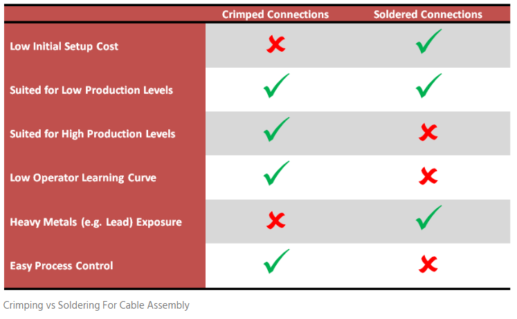
    Getting your cable assembly reliable and easy can be hard on DIYers.  Below is an image from customcable.ca that captures some of the pros and cons of soldering vs. crimping at a high level.

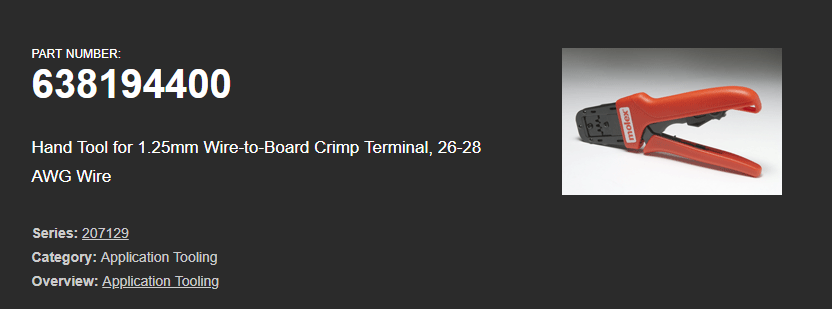
    The biggest problem for hobbyists and DIYers... Crimping doesn't have a low initial setup cost?!?!?  Like I said, crimpin' ain't easy.  But wait!  It's not so bad - here's what we're using for Bobble-Bot.

    If you take a look for this guy, you'll see its priced in the $425 range.  Yikes!  A little steep for some of us, but lets put it in perspective - Can this tool reduce the number of bad connections down the line?  Is it easier and more reliable than soldering?  

    Right now I'm putting together 2 Bobble Bots, each with 60 crimped connections, making 120 connections total - when you have a lot of connections in front of you, any mistake can spiral into hours of lost time troubleshooting or repairing a poor initial job.  If I spend 5 minutes on each connection, I'm looking at 10 hours of work just putting together cables.  That's not super owesome at all.

    The major takeaway: If you plan on doing a lot of cabling, get yourself a crimper.  It will cost a bit up front, but you'll see how much time it saves you down the line.  We reuse this crimper and different styles of the CLIK-Mate connectors for most of our projects that require small gauge wire.  The connectors themselves are cheap and reliable.

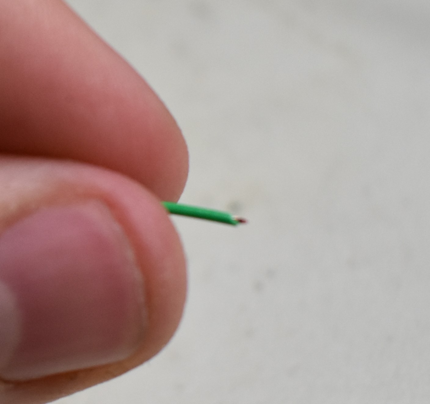
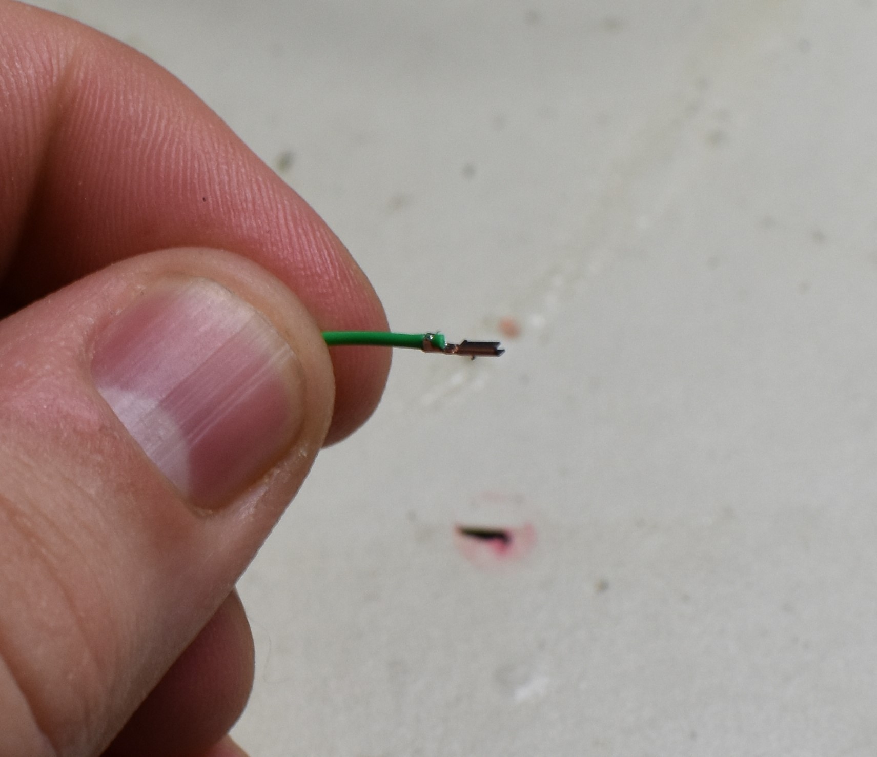
    So, how does one crimp?  The first step is stripping the wire - don't strip too much.  The nice part about crimped connections is you can minimize the amount of exposed wire and not have to use heat shrink.  The back prongs of a CLICK-mate connector are designed to hold onto the insulation of the wire.  Here is a close up of the minuscule amount of wire I stripped off the end - for reference the wire is 28 AWG.

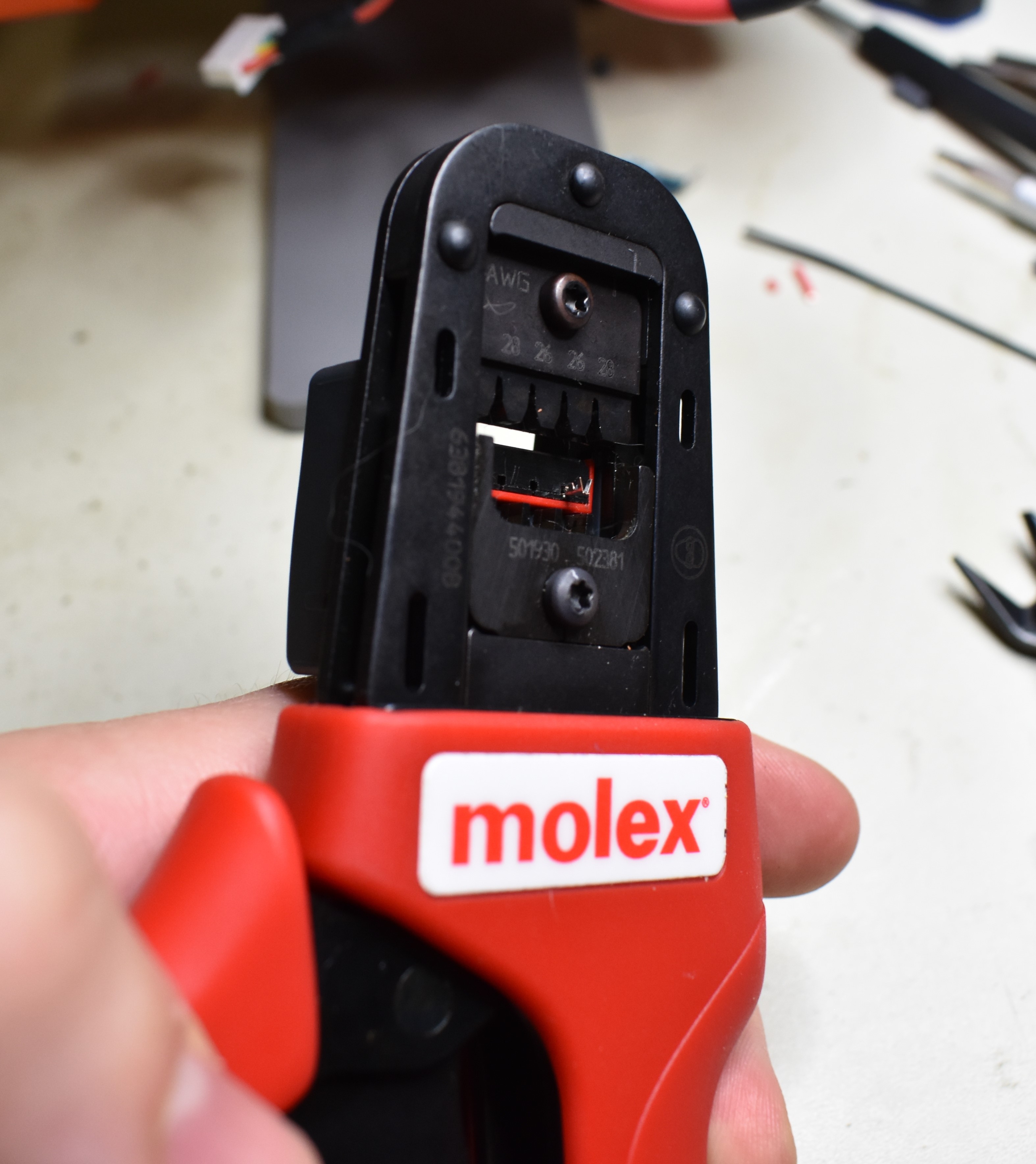
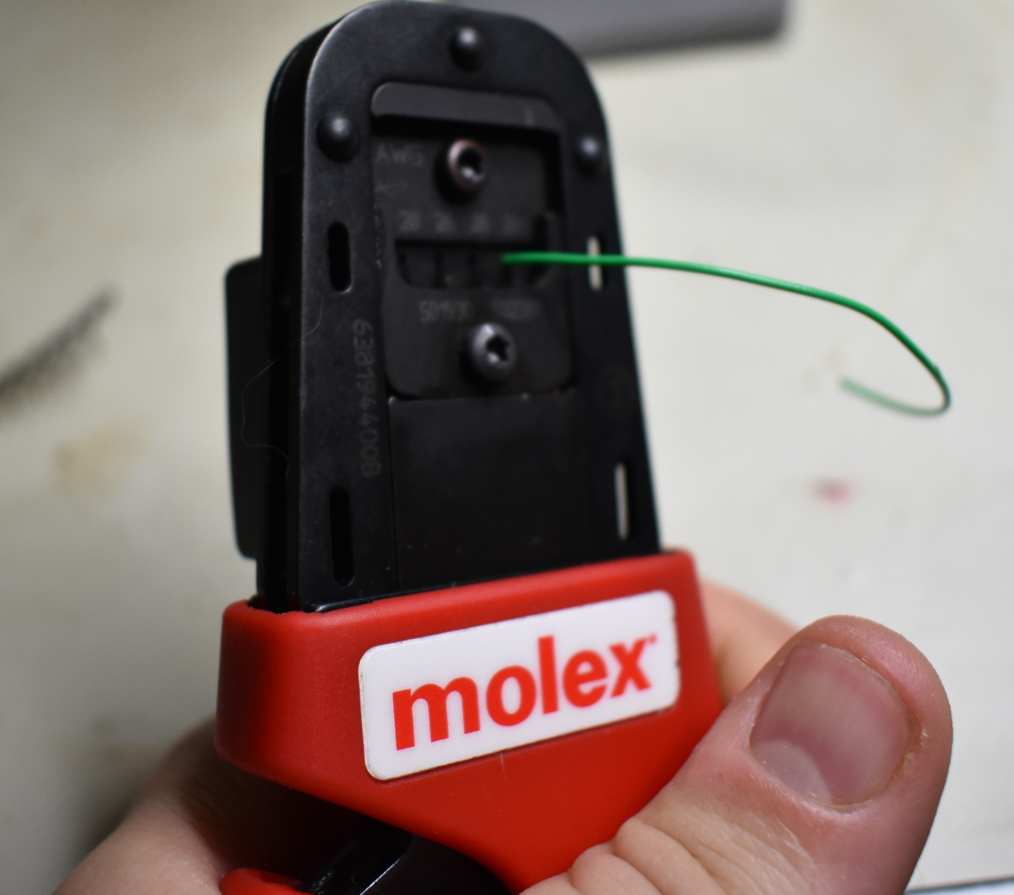
    After that, I insert the connector in the crimper and close the crimper about half way - there is a piece of backing that is used to push the wire against to ensure it is inserted at the proper depth.  Closing half way makes sure the connector is removing most of the room where the wire could mistakenly push through past the backing.

    After that, you just put the wire in and sqeeze the handles down.  Completed crimp below.

    One of the best parts about crimping is you can inspect the connector after it has been crimped to verify your connection is in good condition.  Compare this with soldering, where you could end up with cold joint and the outside still looks OK.  Here's a pic of a good crimp.

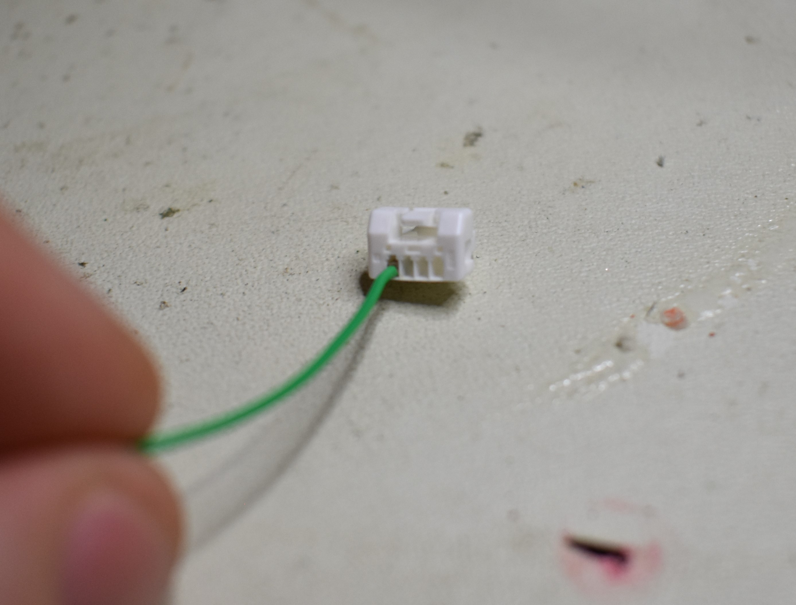
    You can see that the insulation has been grasped by the back tongs and the wire is smushed down under the front tongs.  I always do a pull test after each crimp after visual inspection.  Better to know that its going to come apart before it ends up in a cable.  Slide it into the connector and its done!

    Rinse and repeat 120 times... Maybe a coffee break or two mixed in there and...


    So we have more Bobble Bots on the loose - look for some updates on testing, software, and design refinement in the coming weeks.

    -James

  • Bobble Build: Part 1 - Solder on!

    James Holley05/13/2019 at 04:32 1 comment

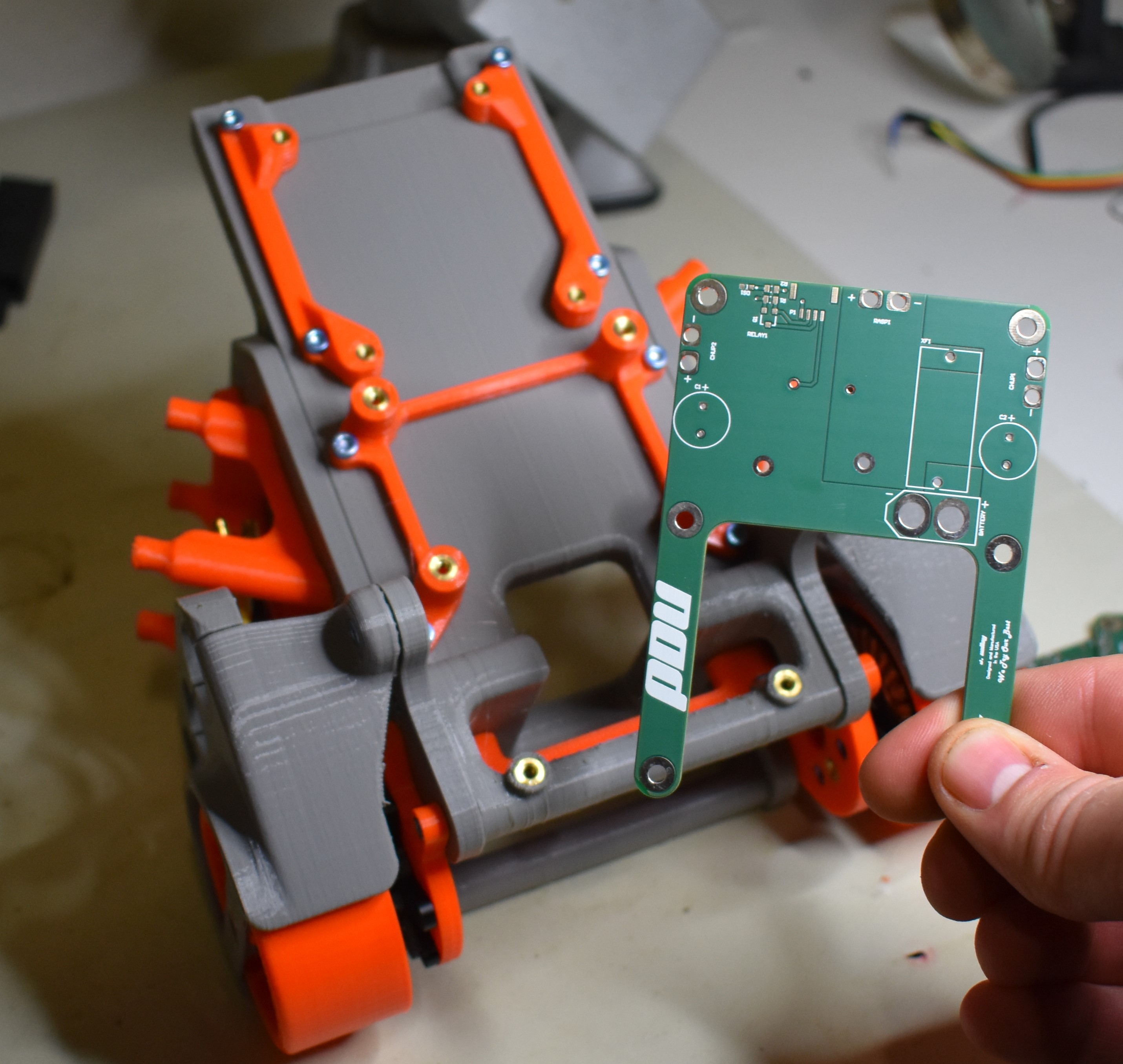
    New PCBs are in, time to start soldering on components!  

    The board we're going to cover in this post is the PDU  (Power Distribution Unit). 

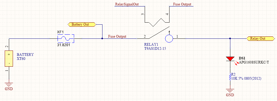
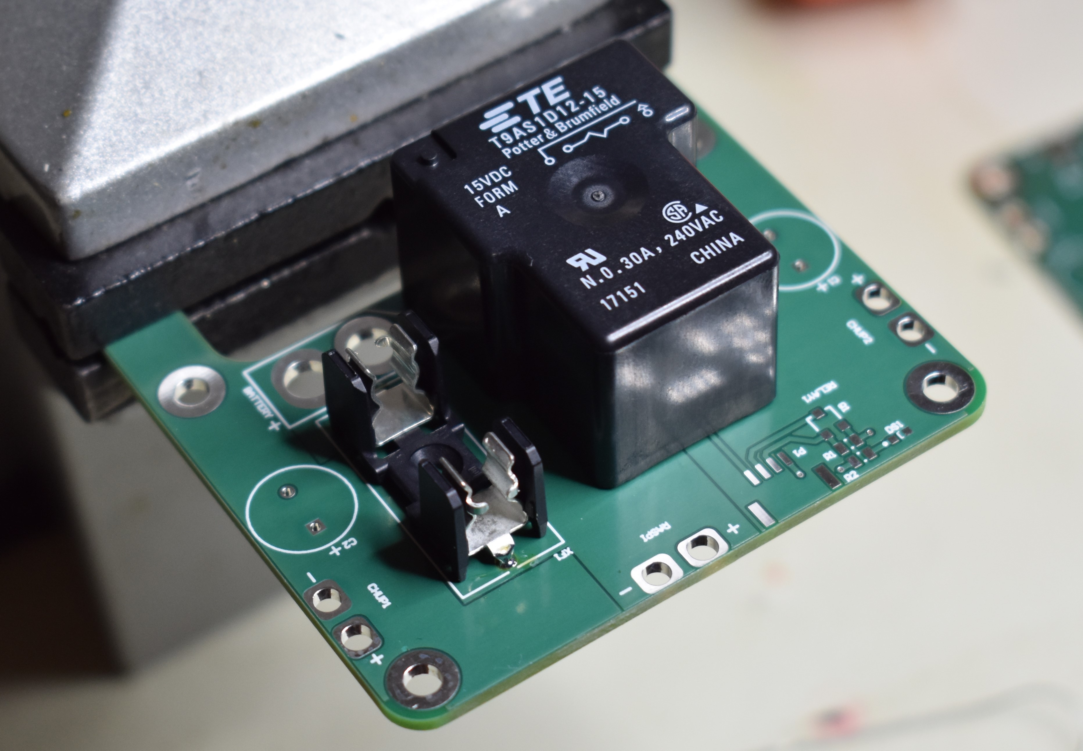
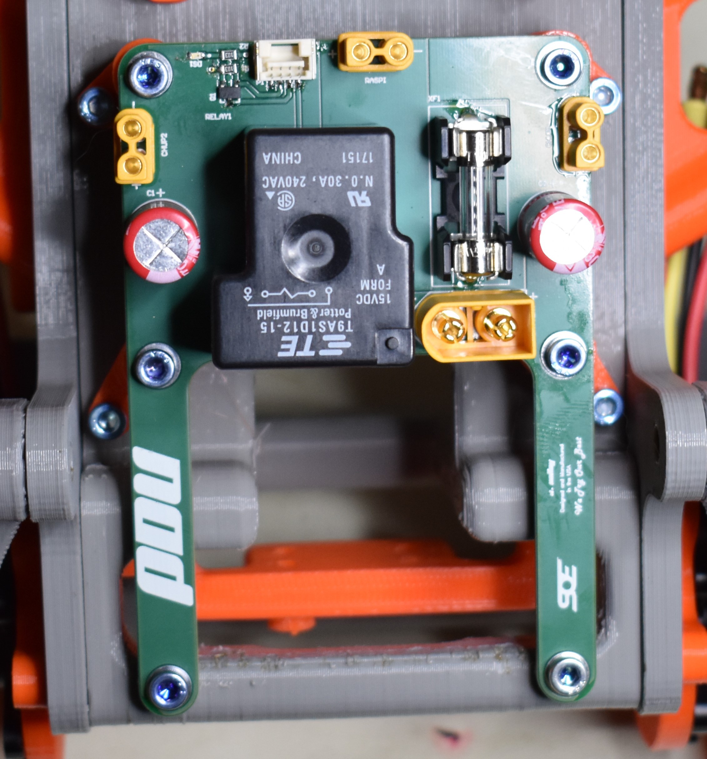
    When it comes to LiPo batteries, I always try to stay on the safer side of things when I can, so the main components are an inline fuse and relay.  The fuse we are using right now is rated to 15A - probably way more amperage than we need, but it will shut off power in case something short circuits.  The relay will be used so that a signal from our on-board computer (Raspberry Pi) will be required to power the motors.  This is nice just in case Bobble Bot takes a spill or the computer loses power, we can cut power to the wheels so our day doesn't get any worse.  Other than that, the PDU just gives us a couple of nice connectors from the battery to boards we want to power - there's not much to it.  The schematic is posted below for anyone that wants to take a closer look or offer any pointers.

    I included a LED so you can see when the relay is closed and power is passing through - don't mess with the bot while the power is hot!

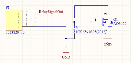
    This is a connector and transistor circuit that completes the relay - pin 2 is connected to the Raspberry Pi GPIO and completes the circuit through the MOSFET.  Pins 3 and 4 can be connected through a switch if you want an additional check on power going through the relay.

    So now... I've chosen some SMT parts for the resistors, transistor, and LED.  Even though these parts are a little trickier to solder, they have some good advantages.  SMT parts are usually cheaper than through hole parts when buying in bulk, so you can save some money down the line if you know you are going to use a lot of them.  If you are ever planning on getting your boards manufactured and assembled, SMT parts are the go to - through hole parts have to be soldered by hand, so you will have to go SMT at this point.  SMT parts take up less board space and they don't stick through the bottom.  This can be helpful for keeping interference with mechanical mounting to a minimum.  And, if you have a little practice, they are not to difficult to solder yourself!  I use a simple technique to help me solder them down - I usually go with 0805 components or larger to make the job easier.  

    I've soldered in my fuse and relay - time to go after the SMT parts to the bottom right of the picture.

    The first step is to get the resistor on the board and to fill one of the two pads with solder.  The other pad is kept clean. Make your life easy - the right pad is soldered here because... well.. I'm right handed, so that's the hand I hold the soldering iron in.  Soldering SMT can be a little delicate, so make sure you set yourself up for success.
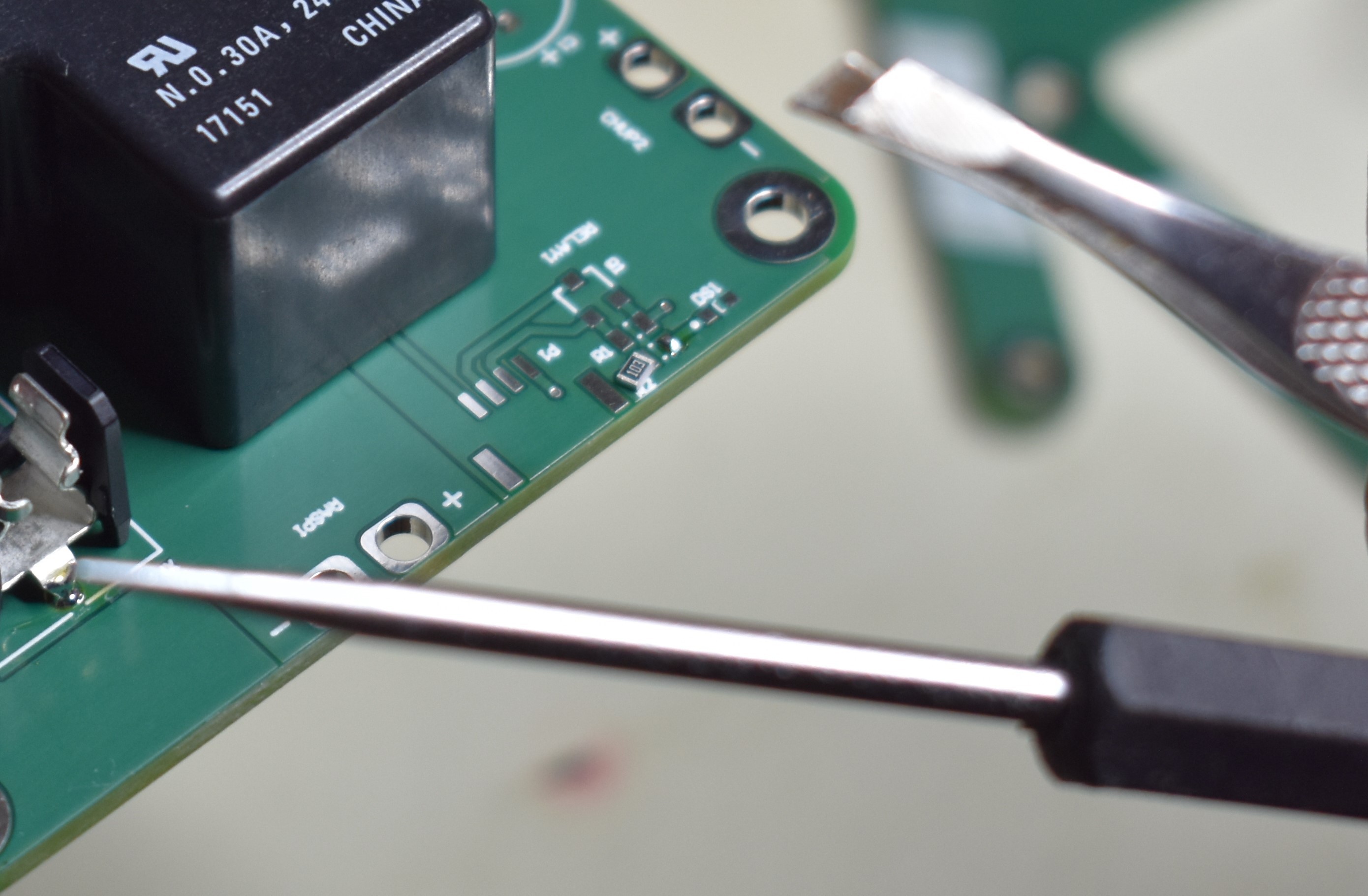
    I have two go to tools for the next step - a probe and a pair of tweezers.  Which one I use depends on the location of the soldering and how big the component is.  For smaller components, a straight probe to push the SMT part is usually more helpful than trying to grab it.  

    Heat up the solder on the pad, and push the part into place - make sure that the part is flush with the board.  A trick I usually use is to hold the part in place with the probe or tweezers and remove the soldering iron first.  Wait for the solder to solidify, and you are good to go.

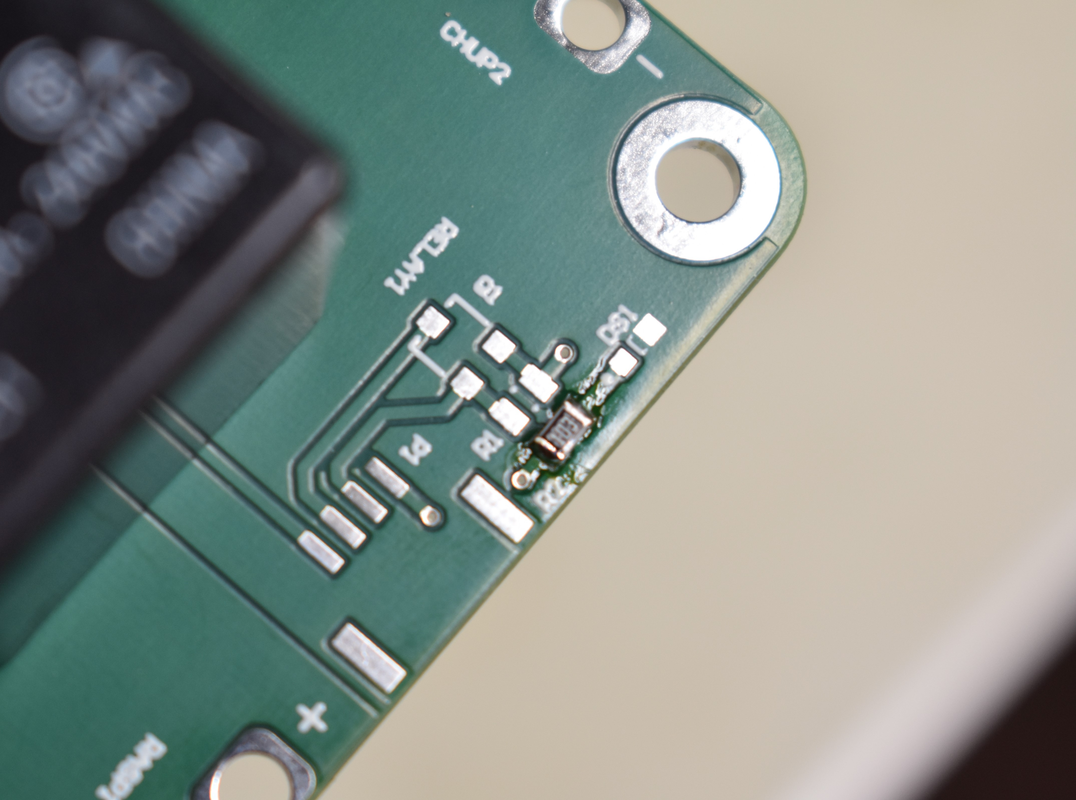
    Once one side is soldered down, you can move to the other pad to complete the job.  Here's a picture of the finished resistor.

    And there you have it!  After that its just rinse and repeat until you get the final product:

    The first PDU is on the newly printed parts, ready for some functional testing!  After that, it'll be time to make cables and get everything wired up. 

    Bobble on,

    James

  • New Bobble-Bot Chassis - A 3D Printing Story

    JSook04/28/2019 at 16:45 0 comments

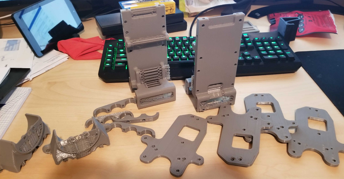
    BB2s We've spent the past month getting two new chassis built, color coordinated this time. Getting the first robot built, tested, and controllable took quite a while. The BB2 robot was designed, built, assembled, and disassembled more times than a sane person would care to count. After getting the mechanical design nailed down, it was a simple task to 3D print a couple fresh chassis - not.
    3D Printing has become the method of choice for manufacturing custom components on the cheap. I'm sure many of you have some experience 3D printing and probably own your own machines. Anyone that owns an entry level 3D printer quickly learns their temperament. Hobby level 3D printing technology has changed the world, allowing an ambitious soul to quickly turn their ideas into reality. When the machine is working, the user is blessed with the ability to manufacture virtually any geometry their imagination desires. Maker-heaven forbid the machine is in a bad mood, a 12 hour print can take a week (ask me how I know). 
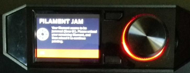
    The construction of BB2 is primarily based on 3D printing. A single bot takes approximately 24 hours of print time. With a few kilos of PLA in hand I started the printing process. Our Makerbot was having none of it. Constant under temperature conditions, filament jams, missed lines, and fan speed errors it would take a few weeks to get the issues under control.
    The Makerbot Replicator+ used to manufacture the bots does have several hundred hours on it, turns out it was time for a significant overhaul. Adjusting the belt tensions helped with missing lines of parts, but didn't entirely solve the issues. To combat the under temperature issue I disabled the PLA cooling fan (relax, not the extruder cooling fan). The extruder was able to hold 215C, but a side-effect is that the parts were extremely stringy with poor surface finishes. Opening and cleaning the extruder helped with filament jams but didn't stop them completely. Another issue I noticed but wasn't able to easily solve was a failure of the Smart Extruder+'s proximity sensor. After wasting far too much time messing with the extruder I traded $200 to Amazon for a replacement. $200 well spent, heater problems were solved, surface finishes improved, overall reliability of the machine was back to something acceptable. I suspect the root cause of the extruder failure is a defective heating element. Before the machine changed it's mind back we printed around the clock until all the parts were completed. 
    I spent another day post processing the parts, cleaning support material away from the larger parts and installing heat-set threaded inserts. Surprisingly, almost all the parts bolted right up save for a few issues with motor fitment. We're installing the electronics on the bots now, standby for another progress update! Coordinated bobbling coming soon.

View all 13 project logs

  • 1
    Get going with the balance controller & simulation

    If you're looking to contribute to Bobble-Bot, the easiest and most affordable place to start is the sim. We use the simulator for all of our software development, and you should use it too. We've gone through great effort to validate and build confidence in our simulator. See our GitHub for instructions on how to build the sim from source

    Start with the controller config file. Mess with some of the gains to see their impact on the control performance. Next, try out changes to the mass properties by making changes to the URDF. Do whatever you want...it's simulation...have fun!

  • 2
    Read the CONTRIBUTING guide.

    We welcome contributions to the project. If they are software changes we insist that you follow the rules outlined in our CONTRIBUTING.md file. Following these steps creates a method to our madness when it comes to software. Most importantly, it allows us to run your changes through a suite of automated software tests that rely on our simulation. The process is key to getting your changes folded in quickly.

  • 3
    Run some test scenarios

    Now that you've got the simulation built and running, it's time to use it to generate some data. The basic steps are provided below, but you can get a whole bunch more detail by visiting here and here.

    source devel/setup.bash
    roslaunch bobble_controllers apply_impulse_force.launch impulse:=-1000 out_file:=~/bobble_workspace/src/bobble_controllers/analysis/impulse_test

     If all goes well, you should see something like this:

View all 8 instructions

Enjoy this project?

Share

Discussions

Keith is building things. Always has been. wrote 11/21/2020 at 03:33 point

Do you have gerber files for the boards? I couldn't find them. 

  Are you sure? yes | no

sanfordjd wrote 11/19/2019 at 15:19 point

Awesome project!  I'm interested in building one using your design but I don't see the CAD files or board schematics. Will those be available to the public?  @Mike Moore @James Holley 

  Are you sure? yes | no

James Holley wrote 11/23/2019 at 00:25 point

@sanfordjd thanks!  We made a big push to get Bobble Bot as far down the road as we could for some of the Hackaday deadlines.  We realize that we came up a bit short with respect to open sourcing the CAD and some of our custom boards.  We are currently going back over the design and restructuring to release more code, a cheaper and simpler build, and have different versions depending on your particular interest.  Please be patient with us and stay tuned!  We will post when we have those ready to go.

  Are you sure? yes | no

mh-nexus wrote 11/08/2019 at 10:05 point

Awesome project with so much attention to detail.

Sorry if you mentioned it and I missed it, but will you provide a kit maybe over e.g. Tindie?

This project requires so many skills, that it will definitely be a useful learning experience. Could you maybe document how you built the CAD models and the URDF model, and some of the design process?

Following along a video as you make the models, and think aloud, would help a lot to acquire such skills.

Thanks again for such a professional product.

  Are you sure? yes | no

Mike Moore wrote 11/13/2019 at 03:16 point

Thanks for the interest and feedback. We do not have a kit ready for sale at this time. We are considering options and working towards that goal. The follow along video idea is a good one and is also something that is in works. 

  Are you sure? yes | no

chetanesd wrote 09/28/2019 at 17:20 point

Hey guys, superb project ! You explained in detail too. Hence, it was a great learning while reading details about Bobble Bot. Thank you for sharing with us. 

  Are you sure? yes | no

JSook wrote 09/28/2019 at 20:15 point

Thanks! We've got a little bit more coming.

  Are you sure? yes | no

matop wrote 08/12/2019 at 19:31 point

Hello, nice project!

Is your robot attitude stable after long use?

  Are you sure? yes | no

Mike Moore wrote 08/15/2019 at 23:33 point

He'll stay continually balancing until he runs out of battery ( maybe 1.5 hrs ).

  Are you sure? yes | no

matop wrote 08/16/2019 at 13:09 point

Nice, your algo are totally robust

  Are you sure? yes | no

Vittorio Loschiavo wrote 06/05/2019 at 19:33 point

I love your project

  Are you sure? yes | no

Mike Moore wrote 06/09/2019 at 21:04 point

I'm glad you like it. Thanks!

  Are you sure? yes | no

Jan wrote 05/13/2019 at 07:36 point

Awesome project. Will follow your progress for sure!

  Are you sure? yes | no

James Holley wrote 05/08/2019 at 02:57 point

What's up @CutterSlade001?  Those are huge inductors...

Bobble Bot is still in the prototyping stage - if you notice between pictures we have different wheel sizes, circuit boards, you name it.  Early on, we were using much bigger motors.  When we started switching around which motors we wanted to use, we put the inductors in there so we didn't have to think as much about changing our motor driver configuration since they would smooth out the current.  We hope that we can finalize the design over the next few months and start optimizing - we will probably remove the inductors electrically (but they look super owesome, so maybe they'll stay on there).

  Are you sure? yes | no

CutterSlade001 wrote 05/07/2019 at 10:10 point

Please tell me, what are the 3 cylindrical objects either side above the wheels? Super caps? Huge inductors? Why? Thanks.

  Are you sure? yes | no

Similar Projects

Does this project spark your interest?

Become a member to follow this project and never miss any updates