-
All software and firmware updated
09/24/2019 at 16:05 • 0 commentsThe Github directory of the project is now usable, and I have updated all the source code that I have written, including:
- The application GUI for the hand module
- The general usage oscilloscope: I use it to log EEG signals
- The SSVEP oscilloscope: derived from the general oscilloscope, but supports games to play with.
- The firmware for all the modules of the prosthesis
- The active vision system source code
I am not that good with documenting source code, but I will try to write instructions for each of the software/firmware.
On the other hand, here are two videos showing you how the oscilloscope works:
Single Channel:
Dual Channels:
-
Project report updated
09/23/2019 at 18:47 • 0 commentsThe project is my capstone project for my undergraduate study, and I have logged the final report to this project directory.
Within the report you will see all the respective researches I have used, as well as all the things you need to know before viewing the project. I have also included all the schematics and software designs within the report.
The report offers complete study on the brain-computer interface used within the scope of this project, as well as the mechanical design and how it evolves throughout this project. There will also parts that give you more in-depth information regarding the EMG schematic, EMG design; and the computer vision system.
-
Gerber file for EMG PCB logged
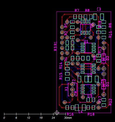
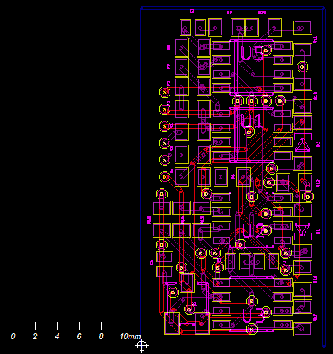
09/23/2019 at 15:21 • 0 commentsI have logged the Gerber files for PCB of EMG sensor. There are three version of 26x50 (mm), 31x16 (mm) and 22x22 (mm). Choose the one that fits your usage. Currently I am building an EMG bracelet (yes, similar to the myo armband currently available on the market. I just want to build one for me from scratch) so I am working with the 31x16 design.
Here are some pictures:
-
Linkage used for design of finger module
09/23/2019 at 15:09 • 0 commentsJust a recap of what I used to design the prosthesis.
Since I am an electrical engineering student, I do not have much experience with mechanism design and simulation. So I have been trying to find an easy and intuitive tool for me to do so. The trajectory of the finger module is designed using Linkage, an amazing and easy to use simulator. You can find more information about the software here: www.linkagesimulator.com
Here is a video of the Linkage project used to create the finger trajectory:
The file is also included in this project of Hackaday.
-
ALL 3D STL FILES UPDATED
09/23/2019 at 14:58 • 0 commentsI have logged all the STL files necessary to create this prosthesis. I have also included 2 .3mf files for the elbow module and the wrist module to guide everyone through the assembly process. Have a look at the video below to understand how to use the .3mf file to find the where does which part go:
I use 3D Builder of Windows to view .3mf
-
Stereo vision for active vision system
09/23/2019 at 13:05 • 0 commentsCurrently, the system simply uses the changes in the total area of the detected blob of the object to figure out the proximity of the object with respect to the palm. I am planning to use stereo vision for it, so that the distance is properly calculated, and that the object handing automation process would be improved. Here is a demo video of the stereo vision currently being developed. More work needs to be done before this is actually realized, but for now, you could more or less figure out what object is closer to the camera through the shades of the pixel.
-
More objects for active vision system
09/23/2019 at 12:18 • 0 commentsI have been wanted to increase the number of supported objects for the active vision system for the prosthesis, as it means that there will be more supported grip patterns corresponding with the objects. Here is my weak attempt of creating a banana classifier.
![]()
-
New EMG PCB finalized
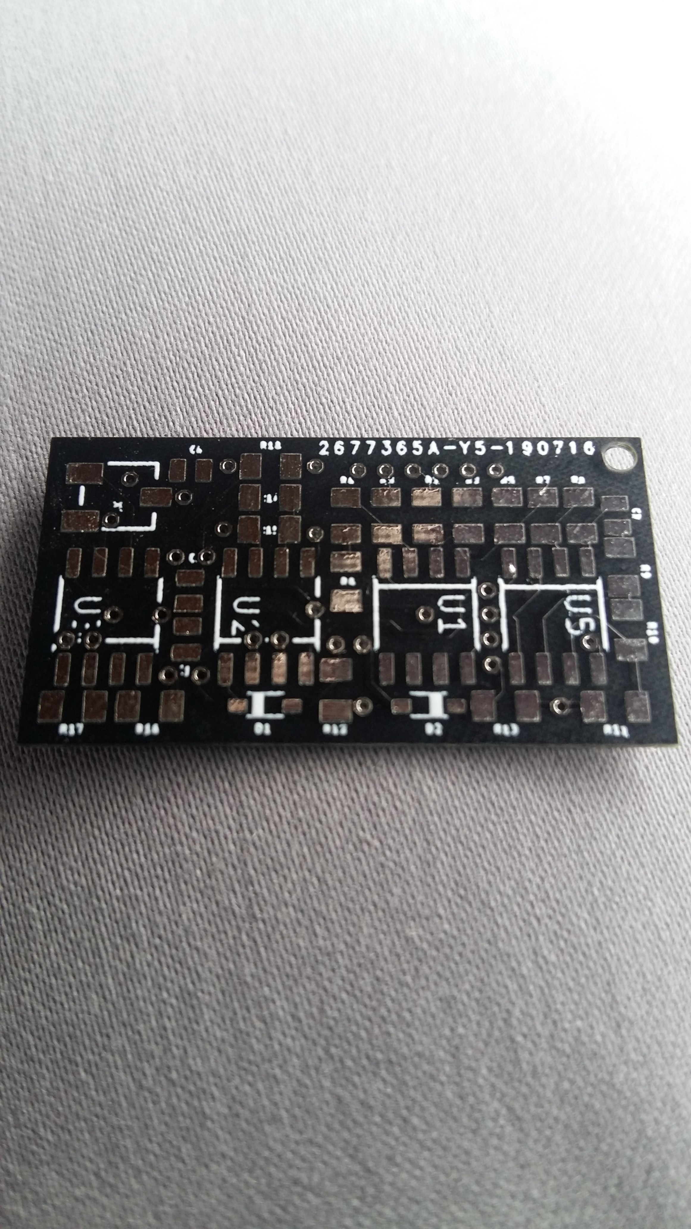
07/25/2019 at 04:44 • 0 commentsTo make the acquisition of EMG signals more easier and more convenient, as well as to increase the number of channels acquired while maintaining the portability of the prosthesis, here is a much smaller PCB design for EMG sensor:
![]()
Current size is 30x16 mm.
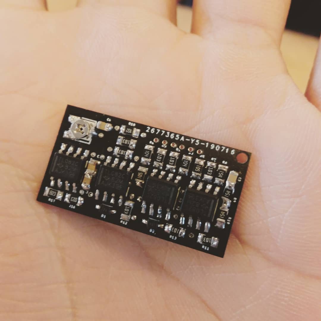
The PCB after soldering:
![]()
-
EMG field test
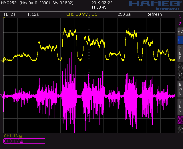
04/19/2019 at 03:43 • 0 commentsThe myoelectric sensor is field tested. The following videos and figures show the signal output and working of the sensor.
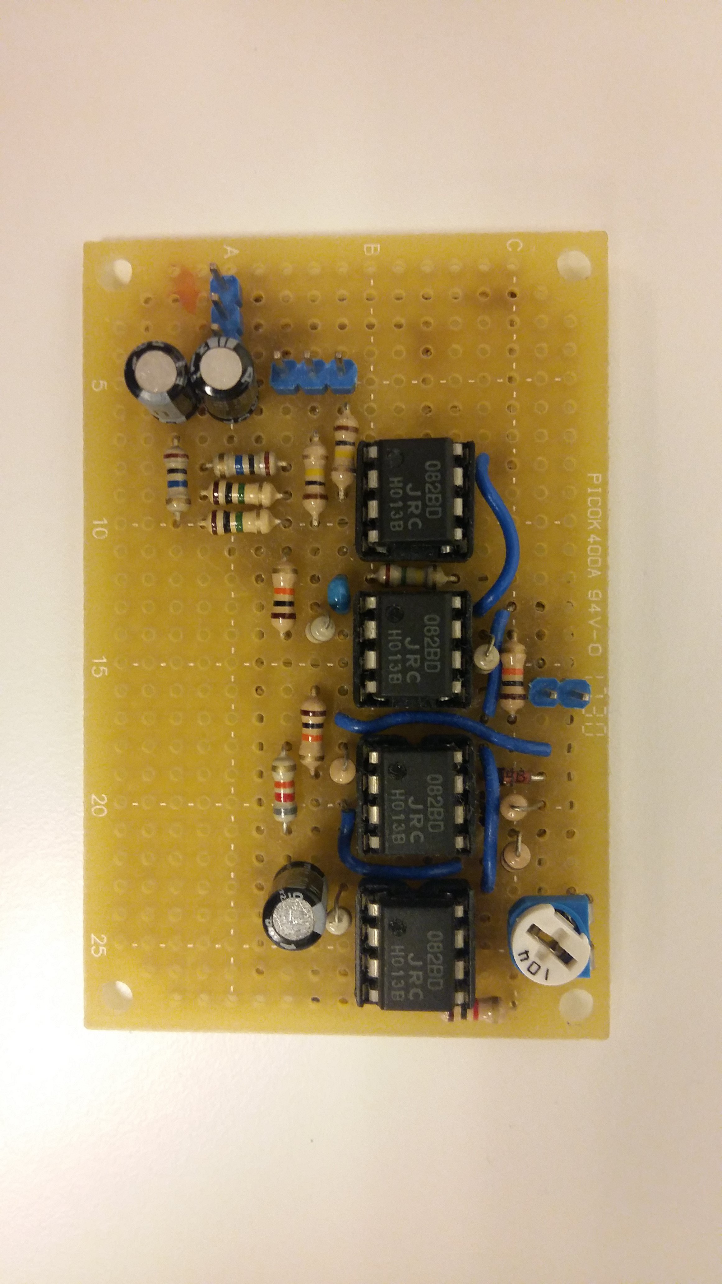
The sensor PCB:
![]()
The signal captured in oscilloscope:
The working demo:
-
Active vision system in action with prosthesis
04/19/2019 at 03:37 • 0 commentsPutting the active vision system into the prosthesis. Demo videos:
Vertical movements:
Horizontal movements:
Putting everything together:
Rotated viewpoint for grip action:
Here only the active vision is working, there is no consent from the user (BCI or EMG). When putting everything together, the system will be more robust and accurate.
3D printed prosthesis with CV, BCI and EMG
An affordable 3D printed prosthesis using computer vision to track and choose grip patterns for the user. Support BCI and EMG as well.
 Nguyễn Phương Duy