A Simple DXF Output Library
Here is a simple DXF output library that may or may not be supported by your CAD package.
Here is a simple DXF output library that may or may not be supported by your CAD package.
To make the experience fit your profile, pick a username and tell us what interests you.
We found and based on your interests.
dxfoutDemo.cAdd graphics to the demo.C Source File - 3.54 kB - 04/26/2019 at 10:53 |
|
|
DXFOutTest.dxfAutoCAD DXF - 1004.00 bytes - 04/21/2019 at 01:50 |
|
|
dxfout.hA simple DXF Ouput librarytext/x-chdr - 4.36 kB - 04/19/2019 at 11:36 |
|
|
dxfoutTest.cA test program fro DXF Outtext/x-csrc - 1.70 kB - 04/19/2019 at 11:36 |
|
|
ezx_graphics.pdfAdobe Portable Document Format - 92.72 kB - 04/19/2019 at 11:36 |
|
|
I used to use one of the "BGI" graphics libraries. A port of the old Borland BGI graphics library. I had a version for Linux and Windows. It's okay but I migrated to "ezxdisp" (http://morihit.net/ezxdisp/) because it was faster and had some useful features. Neither of the libraries will display images.
However, many people still use Windows and porting back to windows and using BGI library is inconvenient. Initially I had a little trouble compiling the Win32 "ezxdisp" library but if you read the "ezxdisp" webpage they point you to how to do it. Install "msys" and use that. Had a little trouble with setting up "msys" but that may have been because my hard disk was almost full.
Anyway, the Win32 (MinGW) library has been compiled and uploaded to my files area.
The main thing is to install the header and library in your preferred location.
Either /usr/include and /usr/lib for Linux, or /MinGW/include and /MinGW/lib for Windows (assuming your using MinGW).
If you really want to you can just copy the files into you code working directory, but remember to tell the compiler and linker to look in the work directory.
This is perhaps the most import thing to know. I usually put a comment to remind me in the source code.
For Linux the linker settings are:
For Win32 (MinGW) it is:
Here is a code snippet on using "ezxdisp":
#include <stdio.h>
#include "ezxdisp.h"

int main(int argc, char *argv[])
{
  ezx_t *e;

  e = ezx_init(200, 200, "no title");
  ezx_set_background(e, &ezx_white);
  ezx_fillcircle_2d(e, 100, 100, 40, &ezx_red);
  ezx_redraw(e);
  ezx_pushbutton(e, NULL, NULL);
  ezx_quit(e);

  return 0;
}
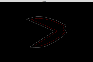
Editing the DXFOut demo to show what it is writing to file.
// Include Libraries
#include <stdio.h>
#include <stdlib.h>

// Please check dxfout.h for function parameter definitions
#include "dxfout.h"

#include "ezxdisp.h"
// -lezx -lX11 -lm             for Linux
// -lmingw32 -lezx -mwindows   for windows (MinGW)

// EZX display structure
ezx_t *disp;

// EZX window size
int width=1200;
int height=700;

// Nominal display scale
double scale=10.0;

int main(int argc,char **argv) {
  printf("DXFOut V1.1 - Written by Alan Cooper (AlanCooper@StartMail.com)\n");

  // Open a new DXF file
  char fileName[128];
  sprintf(fileName,"DXFOutTest.dxf");
  FILE *F1=fopen(fileName,"w");

  // Initialise graphics
  disp=ezx_init(width,height,"Show DXF");
  ezx_set_background(disp,&ezx_black);

  // Create a small box:
  //   Use Shape (closed polyline)
  //   Set Colour 0
  //   Set Layer "Test"
  //   Note: Z coordinate is 0
  DXF_Begin(F1);                        // Required once
  DXF_ShapeBegin(F1,"Test",0);          // Required for each shape (closed polyline)
  DXF_ShapePoint(F1,10,30,0);
  DXF_ShapePoint(F1,30,30,0);
  ezx_line_2d(disp,width/2+scale*10,height/2-scale*30,width/2+scale*30,height/2-scale*30,&ezx_white,1);
  DXF_ShapePoint(F1,30,10,0);
  ezx_line_2d(disp,width/2+scale*30,height/2-scale*30,width/2+scale*30,height/2-scale*10,&ezx_white,1);
  DXF_ShapePoint(F1,10,10,0);
  ezx_line_2d(disp,width/2+scale*30,height/2-scale*10,width/2+scale*10,height/2-scale*10,&ezx_white,1);
  ezx_line_2d(disp,width/2+scale*10,height/2-scale*10,width/2+scale*10,height/2-scale*30,&ezx_white,1);
  DXF_ShapeEnd(F1);                     // Required for each shape (closed polyline)

  // Put a point in the middle
  DXF_Point(F1,"Test",1,20,20,0);
  ezx_point_2d(disp,width/2+scale*(20),height/2-scale*(20),&ezx_red);

  // Make point look like a cross-hair using lines
  DXF_Line(F1,"Test",2,22,20,0,25,20,0);
  ezx_line_2d(disp,width/2+scale*22,height/2-scale*20,width/2+scale*25,height/2-scale*20,&ezx_yellow,1);
  DXF_Line(F1,"Test",2,18,20,0,15,20,0);
  ezx_line_2d(disp,width/2+scale*18,height/2-scale*20,width/2+scale*15,height/2-scale*20,&ezx_yellow,1);
  DXF_Line(F1,"Test",2,20,22,0,20,25,0);
  ezx_line_2d(disp,width/2+scale*20,height/2-scale*22,width/2+scale*20,height/2-scale*25,&ezx_yellow,1);
  DXF_Line(F1,"Test",2,20,18,0,20,15,0);
 ezx_line_2d(disp,width/...
Read more »
First copy the header file (dxfout.h) into your project folder.
Next, add the line #include "dxfout.h" to your program (near the top, perhaps just below the system file headers).
Here is an example (dxfoutTest.c):
/ Include Libraries
#include <stdio.h>
#include <stdlib.h>

// Please check dxfout.h for function parameter definitions
#include "dxfout.h"

int main(int argc,char **argv) {
  printf("DXFOut V1.0 - Written by Alan Cooper (AlanCooper@StartMail.com)\n");

  // Open a new DXF file
  char fileName[128];
  sprintf(fileName,"DXFOutTest.dxf");
  FILE *F1=fopen(fileName,"w");

  // Create a small box:
  //   Use Shape (closed polyline)
  //   Set Colour 0
  //   Set Layer "Test"
  //   Note: Z coordinate is 0
  DXF_Begin(F1);                  // Required once
  DXF_ShapeBegin(F1,"Test",0);    // Required for each shape (closed polyline)
  DXF_ShapePoint(F1,10,30,0);
  DXF_ShapePoint(F1,30,30,0);
  DXF_ShapePoint(F1,30,10,0);
  DXF_ShapePoint(F1,10,10,0);
  DXF_ShapeEnd(F1);               // Required for each shape (closed polyline)

  // Put a point in the middle
  DXF_Point(F1,"Test",1,20,20,0);

  // Make point look like a cross-hair using lines
  DXF_Line(F1,"Test",2,22,20,0,25,20,0);
  DXF_Line(F1,"Test",2,18,20,0,15,20,0);
  DXF_Line(F1,"Test",2,20,22,0,20,25,0);
  DXF_Line(F1,"Test",2,20,18,0,20,15,0);

  // Put a circle around the cross-hair
  DXF_Circle(F1,"Test",3,20,20,0,5);

  // And another box but using polyline (open polyline)
  DXF_PolylineBegin(F1,"Test",4); // Required for each shape (closed polyline)
  DXF_PolylinePoint(F1, 9,31,0);
  DXF_PolylinePoint(F1,31,31,0);
  DXF_PolylinePoint(F1,31, 9,0);
  DXF_PolylinePoint(F1, 9, 9,0);
  DXF_PolylinePoint(F1, 9,31,0);  // Close the box
  DXF_PolylineEnd(F1);            // Required for each shape (closed polyline)

  DXF_End(F1);                    // Required once

  // Close the DXF file
  fclose(F1);

  return 0;
}
And here is the output in a CAD package:
Before you accept that it has worked, check that the boxes and the circle are in fact one polyline and not multiple lines (i.e. individual segments).
For my next post I will look at adding graphical output to the test program.
AlanX
Create an account to leave a comment. Already have an account? Log In.
Possible, I have not really spent much time on GitHub. Spent all my time here.
GitHub is really "unfinished business" for me, I have a lot of code that needs a tidy up and documentation.
Here I can post and document as I go. When I am done I could/should tidy up the project and post it on GitHub.
AlanX
Become a member to follow this project and never miss any updates

 agp.cooper


 Morning.Star
Good project. You can have great success in teaching technology in colleges. I work as a teacher and also a writer at https://supremestudy.com/ and for a long time, I help to write project texts for scientists. Yours is very beautiful. I hope you will be able to advance your experience to a high level.