agp.cooper
-
Project Well Received
12/04/2016 at 00:39 • 0 commentsProject Well Received
I am a little surprised that the project has done so well. But then who would not be interested in a "Spectrum Analyser". It sounds so geeky!
In essence I had partially developed the code for another task and just saw the opportunity for a quick project.
Project logs are a little hard for a novice to follow if they just want to build one, as a log is about the journey rather than the destination. Often just a sentence from someone else's journey is all you need to solve a problem with your project.
So I thought I would post some step by step instructions (well not quite that detailed).
Regards AlanX
-
DigiSpark Version
10/27/2016 at 07:53 • 0 commentsThe DigiSpark (ATTiny85) Version
Well that was the original idea concept.
For the DigiSpark I had to write the LCD code as the DigiSpark does have enough memory for a "frame buffer" making "graphics" rather difficult (so no ready made libraries).
There are lots of code examples on the internet (Jilian Ilett's site is very good one: https://www.youtube.com/watch?v=RAlZ1DHw03g&list=PLjzGSu1yGFjXWp5F4BPJg4ZJFbJcWeRzk).
I used those examples but added the (very limited) graphics that I required.
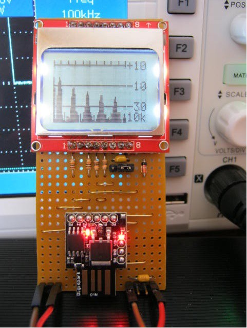
Here is the assembled project reading a 0-3v 1 kHz square wave:
![]() The DigiSpark CPU clock is about 16.5 MHz but the micros() statement appears to assume 16 MHz.
The DigiSpark CPU clock is about 16.5 MHz but the micros() statement appears to assume 16 MHz.I had to scale micros() by 16.9/16.0 to get the correct frequency response.
Here is the adjusted display:
![]()
So all done.
Problems with the DigiSpark
The DigiSpark I am using is a cheap clone and the fuses have not be set to allow the use of PB5, the Reset pin.
Yes if you try to use as an input, it it will reset the DigiSpark, also it will not let you use it as an output.
That is why I said previously the DigiSpark had only 5 IO pins.
Well that can be fixed with a high voltage (12v) programmer so I should look into it if I use the DigiSpark more often.
Also a Reset take 5 seconds to give the USB connection a chance before actually rebooting. That can be fixed as well (there is a no wait boot loader that checks the reset pin status first).
Programming the DigiSpark Fuses
I found this site that steps through the solution:
http://thetoivonen.blogspot.my/2015/12/fixing-pin-p5-or-6-on-digispark-clones.html.
Now I have a ATTiny85 programmer shield for the Arduino UNO so I checked the schematic (all good) and uploaded ArduinoISP.
But if you don't have a sheild then you can just wire it up as per the web-site instructions.
The only thing I did not do is add the Reset capacitor recommended by the web-site..
Next I have XLoader that has AVRDude, so I put a batch file in the directory and ran it.
Now AVRDude is also part of the Arduino IDE so you have a copy of AVRDude.
All good the first time.
Tested the DigiSpark and all good.
Here is the batch file if you ever need it:
Echo Read the signature should be: 0x1e930b
Echo
avrdude -P com5 -b 19200 -c avrisp -p attiny85 -n
pause
Echo
Echo Ready to write fuses? Kill window if not!
pause
avrdude -P com5 -b 19200 -p attiny85 -c avrisp  -U hfuse:w:0x5F:m
pause
AlanX
-
Nokia LCD Version
10/25/2016 at 12:31 • 0 commentsNokia LCD Version
I downloaded the Adafruit Nokia LCD Libraries.
At 5v the LCD contrast was uncontrollable.
Assuming the LCD would be 5v tolerant (really I should have put serial 10k resistors in the data lines) I just powered it with the 3v3 Arduino supply.
It worked fine.
If I wire the CE or CS line low then I only need 4 outputs from the Arduino but I have not told the library as of yet (i.e. have not worked out how to do it).
Mostly a search and replace of "uView" for "display" but there were differences.
As the Nokia display is an extra 20 pixels wide I increased the data area width from 41 pixels to 61 pixels.
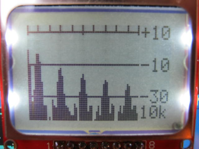
Here is the Nokia working with the 0-3v 1 kHz square wave signal:
![]()
The frequency does seem to be a little off (~5%)? Fixed it by timing every sample run:
![]()
Speed Test
For the above test:
- Sample frequency: 62437 Hz
- Nominal bandwidth: 500 Hz
- Number of samples: 249
- Maximum frequency: 6000 Hz
- Frequency bins: 61
- Noise floor <-30 dB
- Cycle time 760 ms
At 760 ms this is about as a much as this algorithm can do!
If I want more I will have to migrate to DFT.
AlanX
-
Graphics
10/24/2016 at 00:31 • 2 commentsNokia LCD Display
I have a few of these lying around and I wrote some code using a DigiSpark a while back. The code is based on work by Julian Ilett (https://www.youtube.com/playlist?list=PLjzGSu1yGFjXWp5F4BPJg4ZJFbJcWeRzk).
First problem is that the display needs 5 output pins and the DigiSparks only has five IO pins so that is not going to work (i.e. no pin left for the signal input).
I could use an Arduino UNO with the Nokia LCD Display.
MicroView
I have a MicroView so I may as well use that.
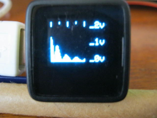
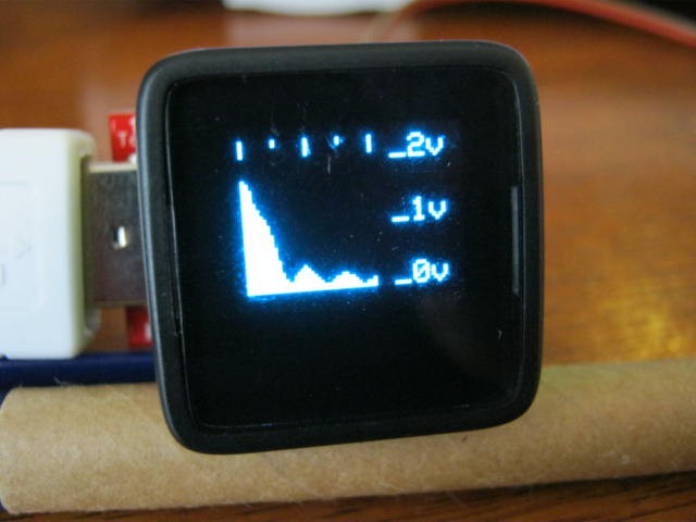
So here it is listening to a 3v 1kHz square wave:
![]()
The top gradations are 0 kHz, 1.25 kHz, 2.5 kHz, 3.75 kHz and 5 kHz.
You can see the DC, 1 kHz and the harmonics but they off a little bit.
Next there is quite a bit of jitter at low frequencies, here is another shot:
The 1 kHz and DC signals have merged.![]()
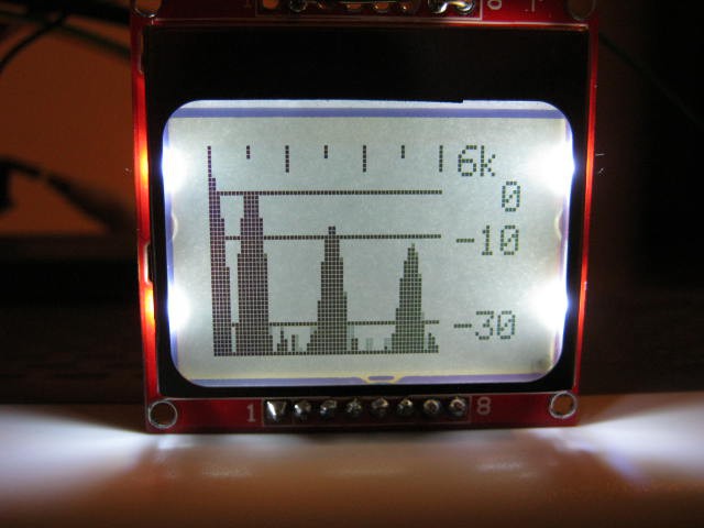
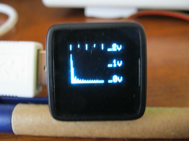
Here is the same square wave but with a 20kHz:
Improvements![]()
Need to check the actual average sample time for each pass.
Need understand the nature of the jitter.
Is it an interrupt or is it due to the algorithm?
Need some free IO pins for an option menu (after I solve the other problems).
Here is the current code:
#include <MicroView.h>

// Audio Spectrum Analyser
#define SampleInput A0   // Name the sample input pin
#define BandWidth  500   // BandWidth
#define MaxFreq   4000   // Max analysis frequency
#define Trigger     10   // Trigger to synchronise the sampler 2vpp at 1kHz = 32

// Define various ADC prescaler
const unsigned char PS_16=(1<<ADPS2);
const unsigned char PS_32=(1<<ADPS2)|(1<<ADPS0);
const unsigned char PS_64=(1<<ADPS2)|(1<<ADPS1);
const unsigned char PS_128=(1<<ADPS2)|(1<<ADPS1)|(1<<ADPS0);

// Setup the serial port and pin 2
void setup() {
  // Setup the ADC
  pinMode(SampleInput,INPUT);
  ADCSRA&=~PS_128;  // Remove bits set by Arduino library
  // Set prescaler
  // ADCSRA|=PS_64; // 64 prescaler (250 kHz assuming a 16MHz clock)
  // ADCSRA|=PS_32; // 32 prescaler (500 kHz assuming a 16MHz clock)
  ADCSRA|=PS_16;    // 16 prescaler (1 MHz assuming a 16MHz clock)

  uView.begin();                          // Start MicroView
  uView.clear(PAGE);                      // Clear page
  uView.println("Spectrum  Analyser");    // Project
  uView.println("0-20 kHz");              // Range
  uView.println();
  uView.println("agp.cooper@gmail.com");  // Author
  uView.display();                        // Display
  uView.clear(PAGE);                      // Clear page
  delay(2000);                            // Wait
}

void loop() {
  static byte *samples;           // Sample array pointer
  static byte *window;            // Window array pointer
  static int N=0;                 // Number of samples for BandWidth
  static long sampleFreq;         // Sample frequency
  long freq;                      // Frequency of interest
  float s;                        // Goertzel variables
  float s_prev;
  float s_prev2;
  float coeff;
  float magn;
  int i;

  if (N==0) {
    // Check sample frequency and set number of samples
    samples=(byte *)malloc(100);
    unsigned long ts=micros();
    for (i=0;i<100;i++) samples[i]=(byte)(analogRead(SampleInput)>>2);
    unsigned long tf=micros();
    free(samples);
    sampleFreq=100000000/(tf-ts);
    N=2*sampleFreq/BandWidth+1;

    uView.setCursor(0,0);                   // Set cursor to beginning
    uView.print("SI: A");                   // Sample input pin
    uView.println(SampleInput-14);
    uView.print("SF: ");                    // Sample frequency
    uView.println(sampleFreq);
    uView.print("MF: ");                    // Max frequency
    uView.println(MaxFreq);
    uView.print("BW: ");                    // andWidth
    uView.println(MaxFreq);
    uView.print("SN: ");                    // Number of samples
    uView.println(N);
    uView.display();                        // Display
    uView.clear(PAGE);                      // Clear page
    delay(2000);

    // Create arrays
    samples=(byte *)malloc(N);
    window=(byte *)malloc(N);

    // Modified Hamming Window
    for (i=0;i<N;i++) window[i]=(byte)((0.54-0.46*cos(2*M_PI*i/(N-1)))*255);

    // Generate test samples
    for (i=0;i<N;i++) {
      samples[i]=(byte)(30*(sin(2*M_PI*i*5000/sampleFreq)+sin(2*M_PI*i*2500/sampleFreq)+sin(2*M_PI*i*7500/sampleFreq)+sin(2*M_PI*i*10000/sampleFreq))+127);
    }
  }

  if (true) {
    // Sychronise the start of sampling with data slicer
    int a0,a1;
    a0=1023;
    for (i=0;i<N;i+=2) {
      a1=analogRead(SampleInput);
      a0=(a0*13+a1*3)/16;
      if (a1>a0+3) break;
    }
    for (i=0;i<N;i++) samples[i]=(byte)(analogRead(SampleInput)>>2);
  }

  // Scan frequencies
  for (freq=0;freq<=MaxFreq;freq+=(MaxFreq/40)) {
    // Goertzel (https://en.wikipedia.org/wiki/Goertzel_algorithm)
    coeff=2*cos(2*M_PI*freq/sampleFreq);
    s_prev=0;
    s_prev2=0;
    for (i=0;i<N;i++) {
      s=0.0000768935*window[i]*samples[i]+s_prev*coeff-s_prev2;
      s_prev2=s_prev;
      s_prev=s;
    }
    // Get magnitude
    magn=2*sqrt(s_prev2*s_prev2+s_prev*s_prev-coeff*s_prev*s_prev2)/N;
    // Display on MicroView
    uView.line(freq*40/MaxFreq,47,freq*40/MaxFreq,10-(int)(20*log10(magn+0.0001)));
  }
  // Frequency graduations
  uView.setCursor(47,0);
  uView.print(MaxFreq/1000);
  uView.print("k");
  uView.line(0,0,0,5);
  uView.line(10,0,10,2);
  uView.line(20,0,20,5);
  uView.line(30,0,30,2);
  uView.line(40,0,40,5);
  // Voltage graduations
  uView.line(0,40,40,40);
  uView.setCursor(47,38);
  uView.print("-30");
  uView.line(0,20,40,20);
  uView.setCursor(47,18);
  uView.print("-10");
  uView.line(0,10,40,10);
  uView.setCursor(47,8);
  uView.print("  0");
  //Display
  uView.display();
  uView.clear(PAGE);
}
Fixes
Measured the sample frequency on the fly.
Dynamically determined the sample number and allocated the memory for the arrays.
For the phase error issue I added a data slicer (with a time out) to try an synchronise the input signal (if possible).
Convert amplitude to a log scale.
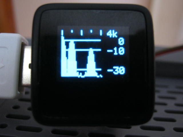
So here it is testing the 1 kHz 3v square wave (using a 500 Hz bandwidth):
![]()
Quite stable - very little jitter.
The magnitude is RMS voltage.
The 4k at the top right-hand corner is the maximum frequency of the analysis.
The nominal band width is 500 Hz (actually 250 Hz before the Hamming Window).
You can see the spectrum noise below -30dB.
Project Complete
Until I find something to do with this project I am going to call it complete!
AlanX
-
Arduino Code for Spectrum Analyzer - No Graphics
10/23/2016 at 14:20 • 2 commentsArduino Code for Spectrum Analyzer
As the DigiSpark has no (working!) serial communications and the ADC for the Arduino UNO is the same for the ATTiny85 (I think), I have prototyped the code for an Arduino UNO. So all done except for the graphics!
Here is the code:
// Audio Spectrum Analyser
#define N 100            // Number of samples
#define SampleFreq 50000 // Average free running speed
byte samples[N];         // Sample array
byte window[N];          // Window array


// Define various ADC prescaler
const unsigned char PS_16 = (1 << ADPS2);
const unsigned char PS_32 = (1 << ADPS2) | (1 << ADPS0);
const unsigned char PS_64 = (1 << ADPS2) | (1 << ADPS1);
const unsigned char PS_128 = (1 << ADPS2) | (1 << ADPS1) | (1 << ADPS0);

// Setup the serial port and pin 2
void setup() {
  int i;

  pinMode(LED_BUILTIN,OUTPUT);
  digitalWrite(LED_BUILTIN,LOW);

  // Setup the ADC
  pinMode(A2, INPUT);
  ADCSRA &= ~PS_128;  // remove bits set by Arduino library
  // Set prescaler
  // ADCSRA |= PS_64; // 64 prescaler (250 kHz assuming a 16MHz clock)
  // ADCSRA |= PS_32; // 32 prescaler (500 kHz assuming a 16MHz clock)
  ADCSRA |= PS_16;    // 16 prescaler (1 MHz assuming a 16MHz clock)

  // Hamming Window
  for (i=0;i<N;i++) window[i]=(byte)((0.54-0.46*cos(2*M_PI*i/(N-1)))*255);
  // Generate test samples
  for (i=0;i<N;i++) samples[i]=(byte)(50*sin(2*M_PI*i*4000/SampleFreq)+50*sin(2*M_PI*i*7000/SampleFreq)+127);

  Serial.begin(9600);
  Serial.println();
}


void loop() {
  int i;
  int freq;
  float s;
  float s_prev;
  float s_prev2;
  float coeff;
  float magn;

  if (false) {
    // Capture the values to memory
    for (i=0;i<100;i++) samples[i]=(byte)(analogRead(A2)>>2);
  } else {
    // Pretend to be working
    delay(N*1000/SampleFreq);
  }

  // Scan frequencies
  for (freq=0;freq<=20000;freq+=1000) {
    coeff=2*cos(2*M_PI*freq/SampleFreq);
    s_prev=0;
    s_prev2=0;
    for (i=0;i<N;i++) {
      // Goertzel
      s=0.0000768935*window[i]*samples[i]+s_prev*coeff-s_prev2;
      s_prev2=s_prev;
      s_prev=s;
    }

    // Get magnitude
    magn=2*sqrt(s_prev2*s_prev2+s_prev*s_prev-coeff*s_prev*s_prev2)/N;

    Serial.print("Freq: ");
    Serial.print(freq);
    Serial.print(" Magn: ");
    Serial.println(magn);
  }
  digitalWrite(LED_BUILTIN,!digitalRead(LED_BUILTIN));
  delay(1000);
}
Here is the output:
- Freq: 0 Magn: 2.67
- Freq: 1000 Magn: 0.00
- Freq: 2000 Magn: 0.00
- Freq: 3000 Magn: 0.00
- Freq: 4000 Magn: 0.53
- Freq: 5000 Magn: 0.00
- Freq: 6000 Magn: 0.00
- Freq: 7000 Magn: 0.53
- Freq: 8000 Magn: 0.00
- Freq: 9000 Magn: 0.00
- Freq: 10000 Magn: 0.00
- Freq: 11000 Magn: 0.00
- Freq: 12000 Magn: 0.00
- Freq: 13000 Magn: 0.00
- Freq: 14000 Magn: 0.00
- Freq: 15000 Magn: 0.00
- Freq: 16000 Magn: 0.00
- Freq: 17000 Magn: 0.00
- Freq: 18000 Magn: 0.00
- Freq: 19000 Magn: 0.00
- Freq: 20000 Magn: 0.00
Which is correct!
Note that the magnitude calculation is not 100% accurate.
The DC component should be 2.49v rms (not 2.67) and the two frequencies (4000 Hz and 7000 Hz) should be 0.5v rms (not 0.53). The error issue is understood to be due to "phase" errors and "Window" errors.
Execution time:
- sampling 2.0 ms
- calculation per frequency 1.2 ms
- Total time (21 frequencies) 27 ms
So all good!
AlanX
-
An Integer Version of Goertzel Algorithm
10/23/2016 at 10:25 • 2 commentsATTiny85 Migration
Migrating the test code to ATTiny85 requires some optimisation to suit the limitations of the processor program, RAM and execution speed.
The ATTiny85 has;
- 512 bytes of SRAM
- 8k bytes of EEPROM
- ADC conversion time (10 bits ~125 kHz) but can be clocked higher (~1 MHz) for less accuracy.
SRAM will be the main limitation.
*** Big mistake ***
The 125 kHz specification is the ADC clock speed, not the conversion speed.
It takes 25 cycles for the first conversion and then 13 cycles per conversion.
This is 9.6 kHz!
All is not lost, I can speed (http://www.microsmart.co.za/technical/2014/03/01/advanced-arduino-adc/) clocked his code on an AVR at an average of 20.5 us (48.8 kHz).
Not enough for a 40 kHz ultrasonic tone converter but enough for an audio spectrum analyzer.
Integer Goertzel
Can I avoid floating point maths?
My first attempt a while back failed.
I did not really try to work it out then.
This time I set up variable shift fixed point maths.
Using long (32 bit) failed for low frequencies (i.e. 100 Hz).
Using long long (64 bit) worked for shifts between 15 and 20:
Integer Goertzel Numerical Stability Frequency 100 Hz Data Type Magnitude Error Single 105.0406 0.001% Double 105.0415 0.000% Long long fixed point Shift 13 92.559 11.883% 14 100.272 4.541% 15 104.327 0.680% 16 104.329 0.678% 17 104.329 0.678% 18 104.846 0.186% 19 104.846 0.186% 20 104.976 0.062% 21 121.582 -15.747% 22 108.954 -3.725% Single precision (float) work okay as well.
As long long takes as long as float to process there is no advantage to using integers for this algorithm!
If you are wondering what variable shift fixed point code looks like, here is the critical bit of code:
    coeff=(long long)(2*cos(2*M_PI*freq/SampleFreq)*(1<<shift));
    s_prev=0;
    s_prev2=0;
    for (i=0;i<N;i++) {
      // Goertzel
      s=(window[i]*samples[i]>>shift)+(s_prev*coeff>>shift)-s_prev2;
      s_prev2=s_prev;
      s_prev=s;
    }
Yes, all you do is scale everything up before use, using "*(1<<shift)" and scale any multiplications down using ">>shift".
AlanX