Andy Geppert
-
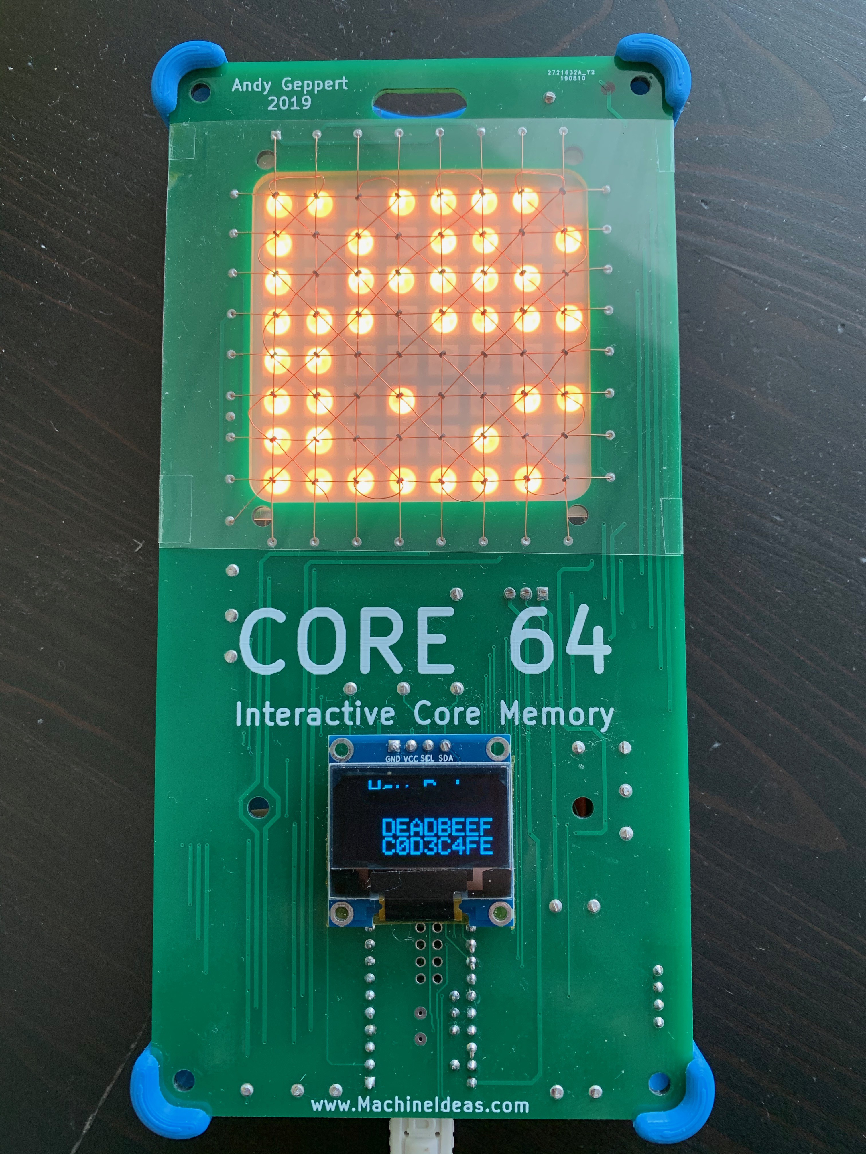
0xDEADBEEF
03/01/2020 at 18:17 • 1 commentUpdated with a Hex mode demo video:
Finally got a new mode working, thanks to the suggestion of Morgan. This mode displays the HEX values of the 64 bits, aka 16 nibbles or characters. The upper left nibble on the LED array is the first HEX character, and the lower right nibble on the LED array is the last HEX character. Stated another way, when the LED/CORE array is used as a 64-bit value, MSb is upper left, LSb is lower right.
![]()
I split the nibbles into two rows of eight for the OLED display in order to clearly display some "English" hex words. Yes, it is interactive too! I'll share a video when the OLED stability issue is resolved. The text keeps drifting across the screen, and it's very annoying. I need to figure out if this is an electronic or firmware logic or library problem.
-
Video Demo - Core 64 Prototype is fully functional!
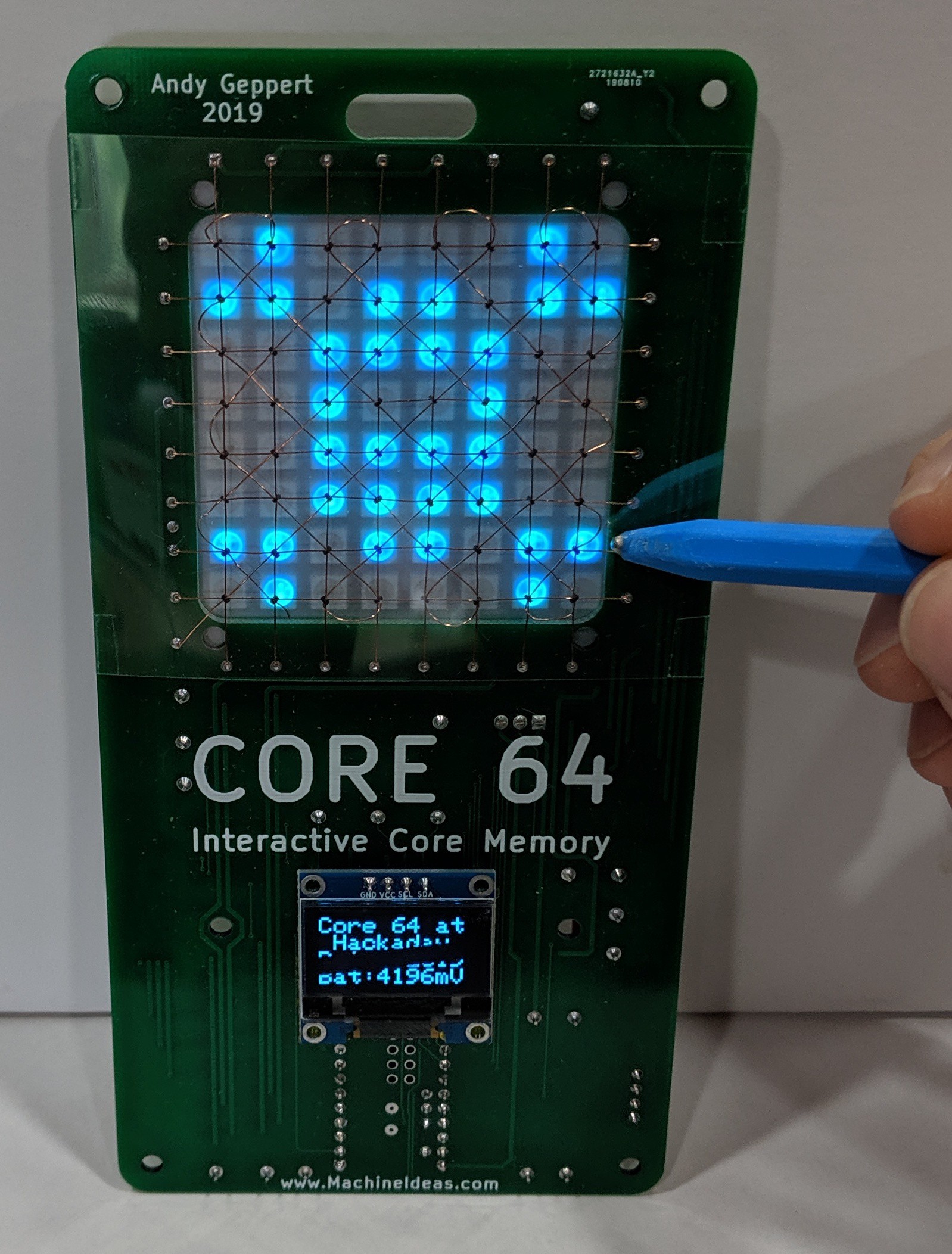
02/27/2020 at 06:01 • 0 commentsThis video shows and describes the "core" functionality I've been trying to achieve. It's a great feeling to finally be at this point in the project! Even though I've had the scrolling text working for awhile on it's own, I'm now able to make it truly interactive by using the core memory as screen RAM.
I've said it before, but you really do have to experience this to get the feel for how fluid and interactive it is. It is satisfying to use the stylus on the cores, and have the LEDs instantly respond. The mode where the LEDs constantly show the extent of the magnetic flux is similar to moving sand in a zen garden. It just flows.
I'm noticing some unexpected behavior, which might inspire some new ideas. First, when I hold the stylus with very little pressure, it wants to jump between cores, trying to stay aligned to a discrete core. The effect is subtle, but noticeable. I didn't expect to be able to feel the interaction with the cores. And the second unexpected thing is that I can hear the cores resonating. In all three modes that I've demo'd in the video, the cores are constantly being written to and read from. That translates to a faint ringing noise that I can hear when the badge is close to my ear.
This continues to be a project with unexpected twists and interesting things to learn. I hope to be able to sell some kits before the end of 2020.
-
Core sense reliability improved!
02/22/2020 at 16:32 • 0 commentsThe core sensing is now working much more reliably, at least from the perspective of what the MCU can sense. I reduced the threshold required for the Op-Amps to register a change in the sense wires from 22mV to 11mV (corresponds to a 22 Ohm and 11 Ohm resistor change). The increased sensitivity provides a longer output pulse, and gives the MCU more time to see the signal. An improvement I'm considering in a future version is to add a flip-flop as a buffer to make it easier to catch the sense pulse. Right now the timing requirements are very tight, and I am disabling interrupts and using digitalReadFast to catch the core sense wire changes.
A significant part of this project is to enable others to experiment with the design of the firmware and the core control schemes. I am working toward a clean system architecture (both in the firmware and electronics) with robust sample code and APIs. This opens the door to experimentation at any level of the system.
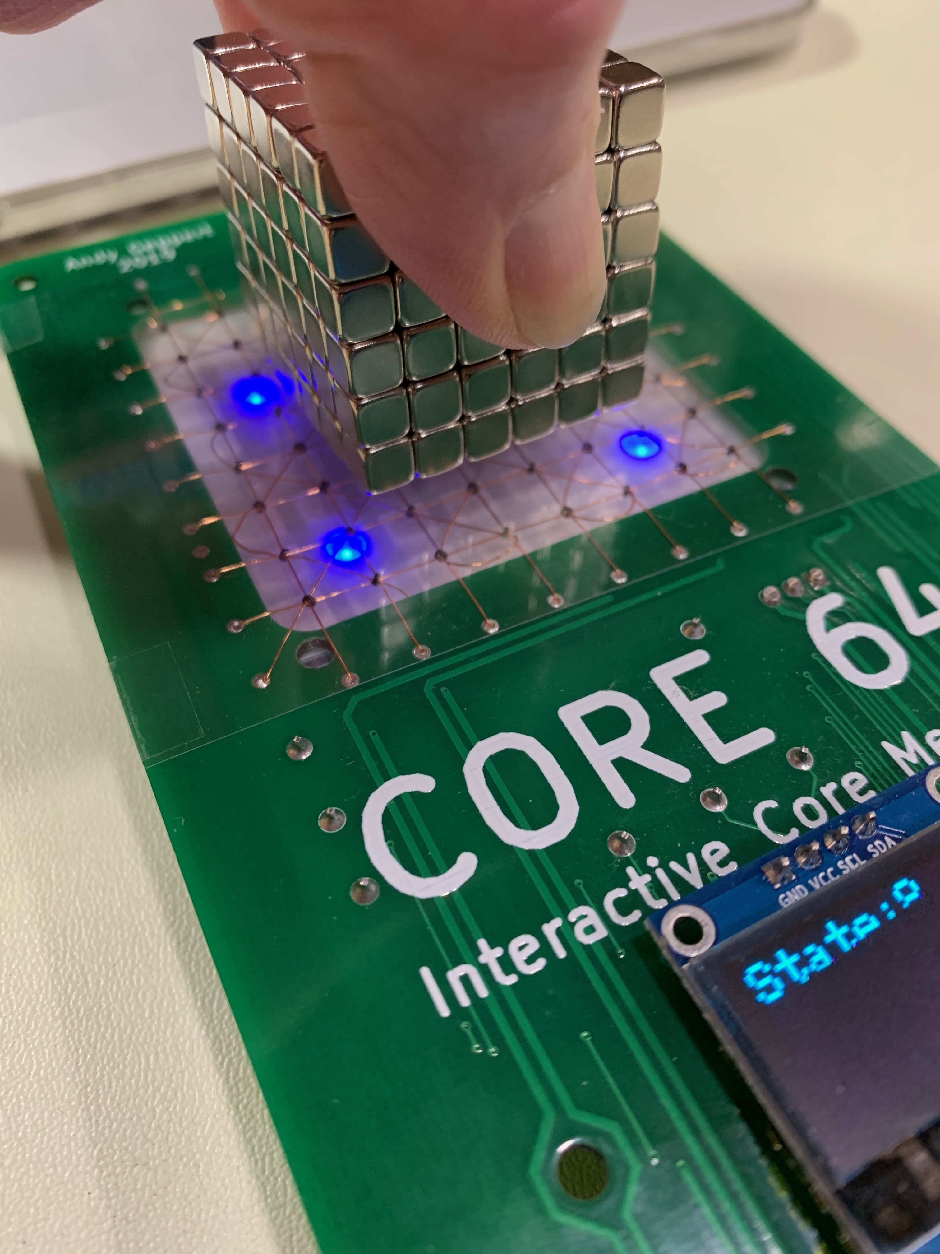
Even at this stage of functionality, there is a lot of fun to be had. For instance, holding this cube of magnets above the cores does not affect all of the cores as you might expect. It only affects the cores at the four corners, where the magnetic flux is far less constrained. This mode of operation is what I call "flux detection" mode. The cores are all being polled every 12 ms, with a corresponding LED array update, to show which cores are effectively being blocked from polarity changes as the 1's and 0's are written. It's highly INTERACTIVE!
![]()
Of course, if the cube is held closer to the cores, there is enough flux leakage on the whole surface to affect all of the cores under the magnets.
Next up, some multicolor drawing with persistent pixel changes.
Coincidentally, I just hit a total of 160 hours into this project with this milestone update. That's 4 weeks of full-time work, spread over many months... When I started this, I had the proof-of-concept running, and had just begun watching a great video series on how to use KiCAD. Thank you Shawn Hymel and Digi-Key! This project is my first time designing a PCB from scratch. 10 out of 10, would do again!
-
I can draw!
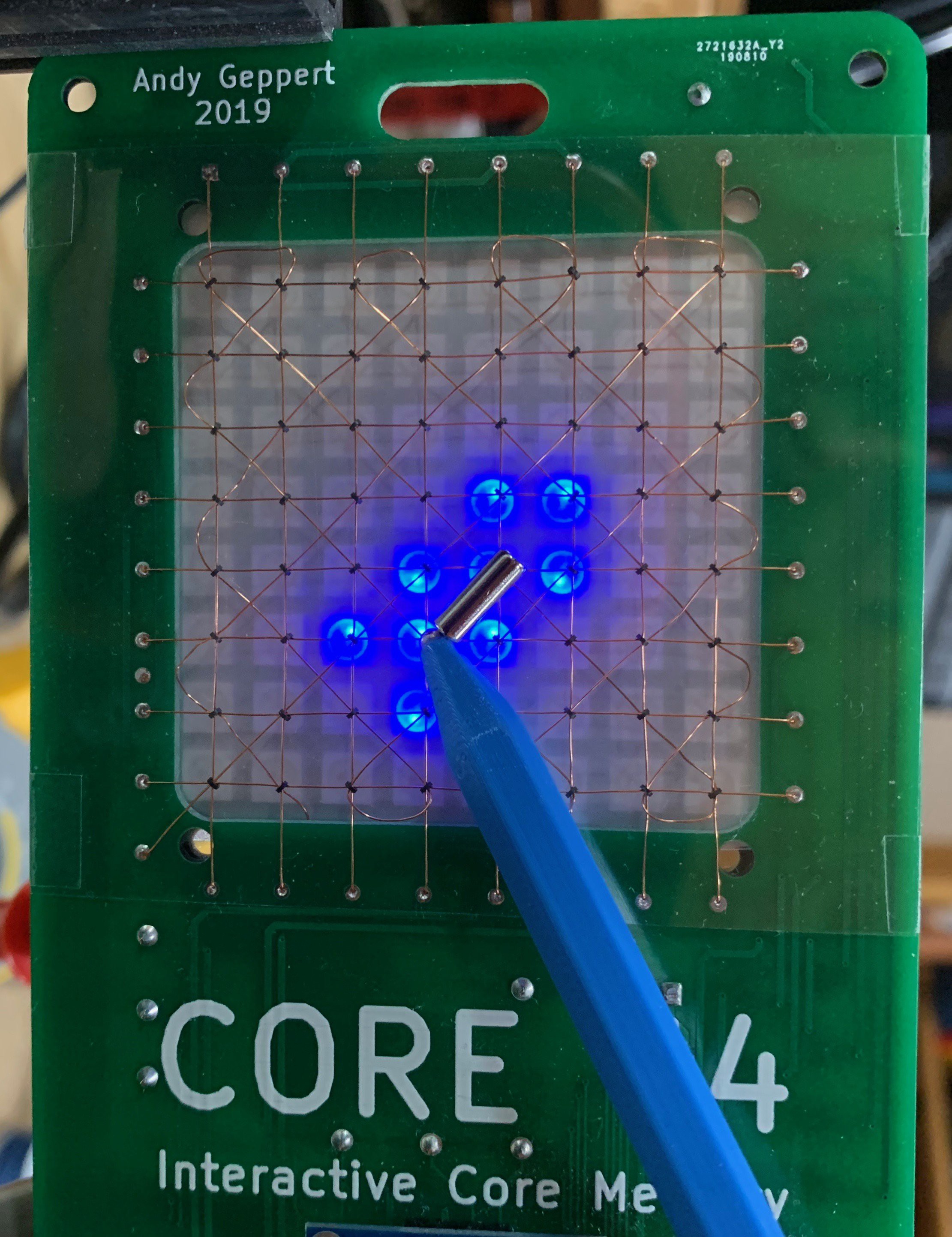
02/22/2020 at 13:55 • 0 commentsI can now draw on the screen for real! This means all of the cores are working with both reads and writes, and the the LED matrix is showing the state of the cores in realtime, with an overall refresh rate of 12ms. The following image shows the extent of the flux from the cylindrical magnet on the end of the stylus.
![]()
This milestone has been a long time coming. The breakthrough I made was the discovery that my shared use of a GPIO pin for one of the matrix drive transistors and the LED array was causing interference. The effect was that quickly strobing the matrix transistor fooled the LED array into thinking it was receiving valid data. The array is driven by a series of pulses, and if they are close enough together (less than about 150 us) the first few WS28128 LED pixels in the string start to illuminate. This is a design problem that is obvious now. But fortunately everything is still happening fast enough when I added a necessary delay, a firmware change overcomes the issue. In the next prototype, I plan to implement two 3-8 binary decoders to free up some IO on the Teensy LC. I was already overlapping some of the IO usage, and could use some headroom for other functionality that I need to add. The core matrix itself requires 20 transistors on its own.
There are several more hurdles to resolve related to the functionality outside of the cores/LEDs, but the last two hurdles I have to solve for the cores is the sensing signal and the half-select currents. Those need to be tuned up to operate 100% reliably with a wider range of power supply voltage. I am seeing occasional flashes on the LED matrix which are indicating that sometimes the core flip is not being sensed. The allowable input voltage range right now is 3.3 to 4.0V, which works OK with the LiPo battery I'm using. But it needs to be more reliable.
Also looking forward to the next PCB layout, so I can update it to say 2020!
-
ALL 64 CORES ARE WORKING! FINALLY!
02/18/2020 at 02:56 • 0 commentsThe learning continues, and this time with some success to show for it!
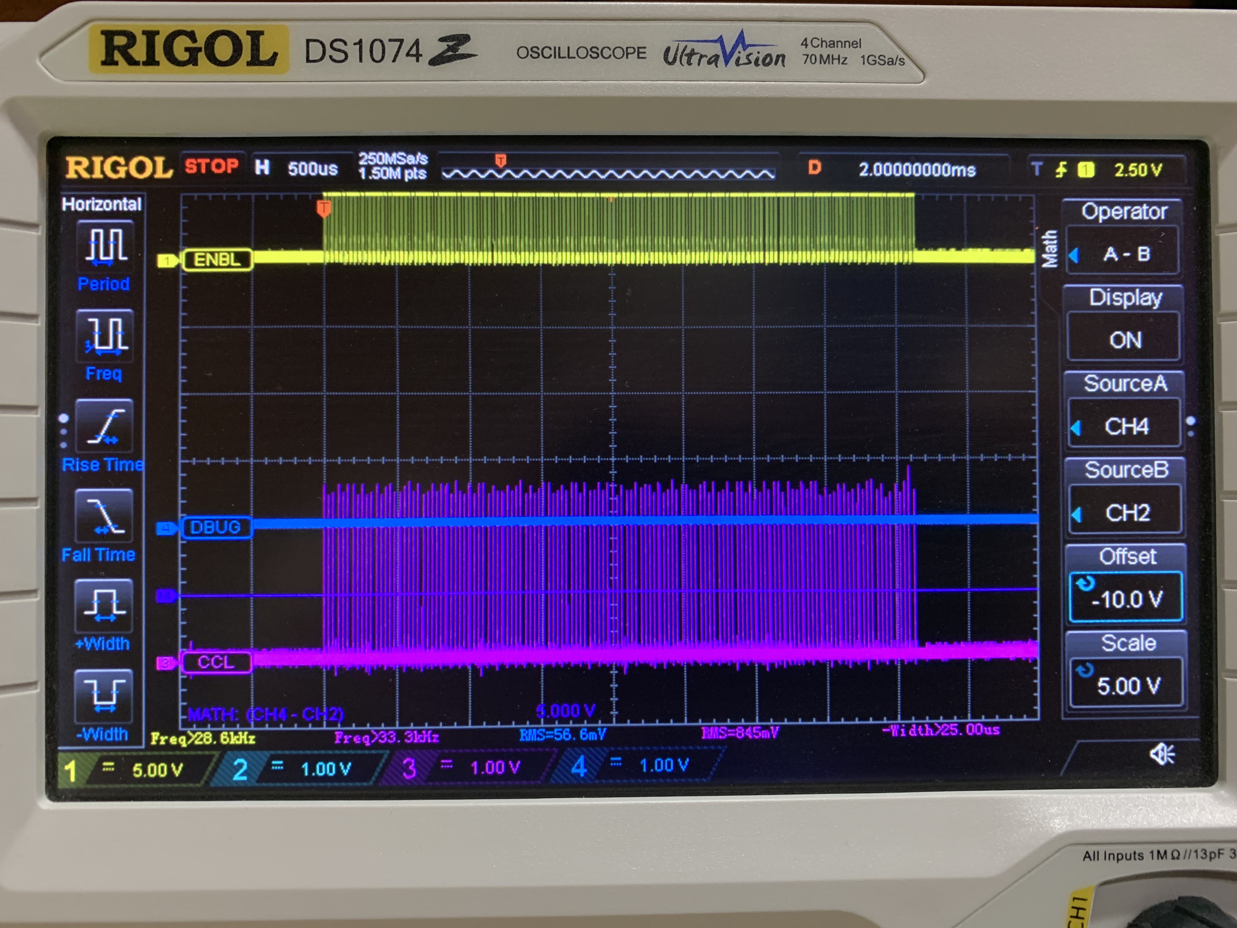
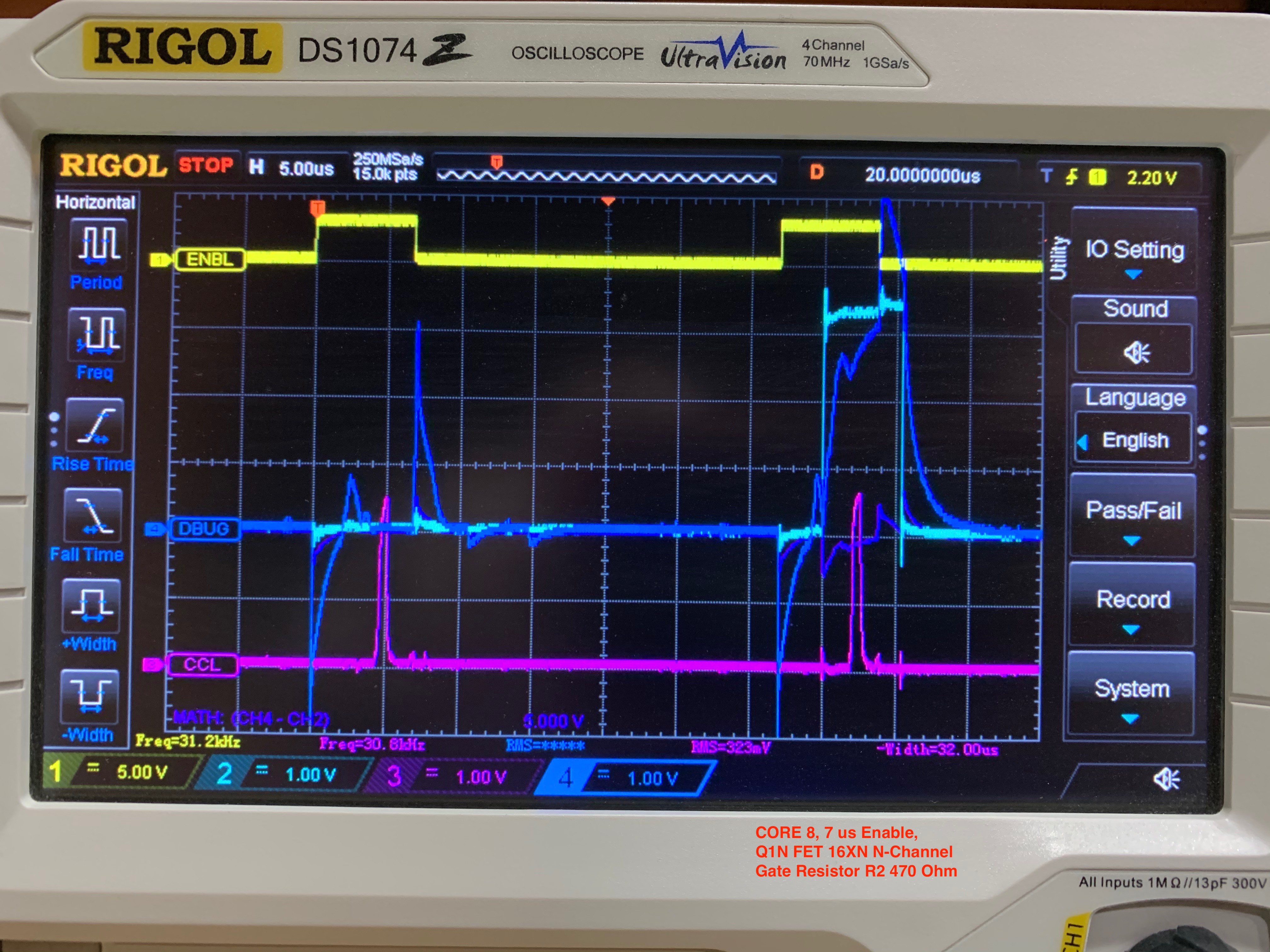
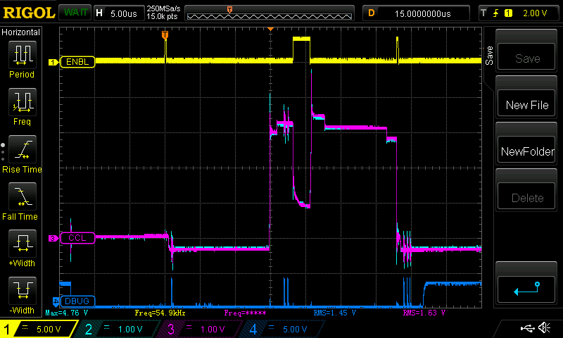
Here are all 64 cores, each being written to with a 0 and then a 1.
![]()
Yellow trace is the ENABLE during each write, and the purple trace is the sense wire pulse that indicates the core changed polarity.
In the last update I grafted in an OR gate and corrected a +/- swap on one of the Op-Amps. That brought the sense circuit to life. But there was much more ground to cover. Here are the ugly details.
1) The cores were not behaving in the right arrangement with the LEDs. The fix was to map the electromagnetic core addressing to the physical layout of the array. In the standard core array design I am using, in order to keep the component count minimized, the cores are placed in an alternating sequence. In other words they cant left, then right, then left, and so on. If one ignores that fact, the consequence is that writing a 1 to bit 0 is in the first column of the first row, and then bit 1 is on the 2nd column... but on the fourth row. I implemented a look-up table array to get them all in order. This is important because I am physically mapping the cores as screen memory to the LED array directly underneath. They must line up.
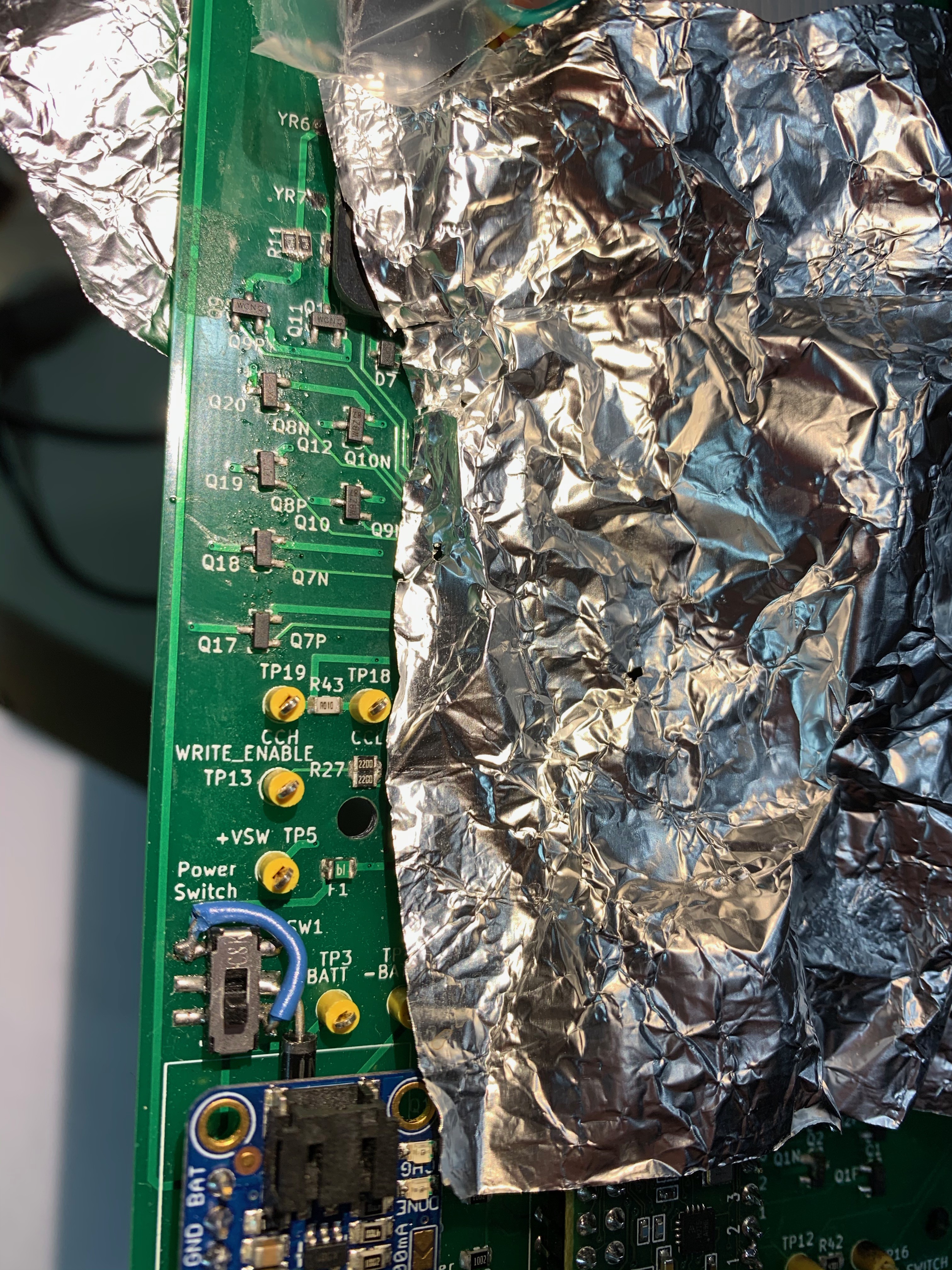
2) Then I found that some cores worked, and some didn't. Sometimes the first four in a row, sometimes a whole row. In some rows, nothing worked. Is it a coding problem? Another circuit design problem? Bad components? Assembly error? All of the above?
![]()
3) The first row wire was intermittent. Cold solder joint. Easy fix.
4) Awhile back, in an effort to get things working, I made the mistake of trying out FETs instead of transistors. I was looking to drive more current in the core matrix wires. If you drop FETs into a circuit designed for transistors, without the additional components that make FETs work correctly... you get something that kinda works. The signals to the gates look, um, not square:
![]()
Cyan trace is the MCU side of the gate resistor, and the blue trace is the gate side of the resistor. That was a bad idea. So I started swapping FETs back to the original transistors, and things started working more and more. The most problematic FETs were the ones used in conjunction with the diode bridges (again, that's to minimize parts count). In some cores, I was seeing TWO sense pulses when there should have been one. Bottom line: design correctly to use FETs if you are going to use FETs. They require more care than transistors to implement. Things got much better with transistors:
![]()
You might notice another difference between the last two scope captures. The yellow line is the enable signal, and moving that turn-on and turn-off away from the matrix transistor changes helped square things up. I know the cyan and blue traces aren't as square as I'd like, and there is more to learn... but it works consistently now. And the overshoot isn't much to worry about, I reckon.
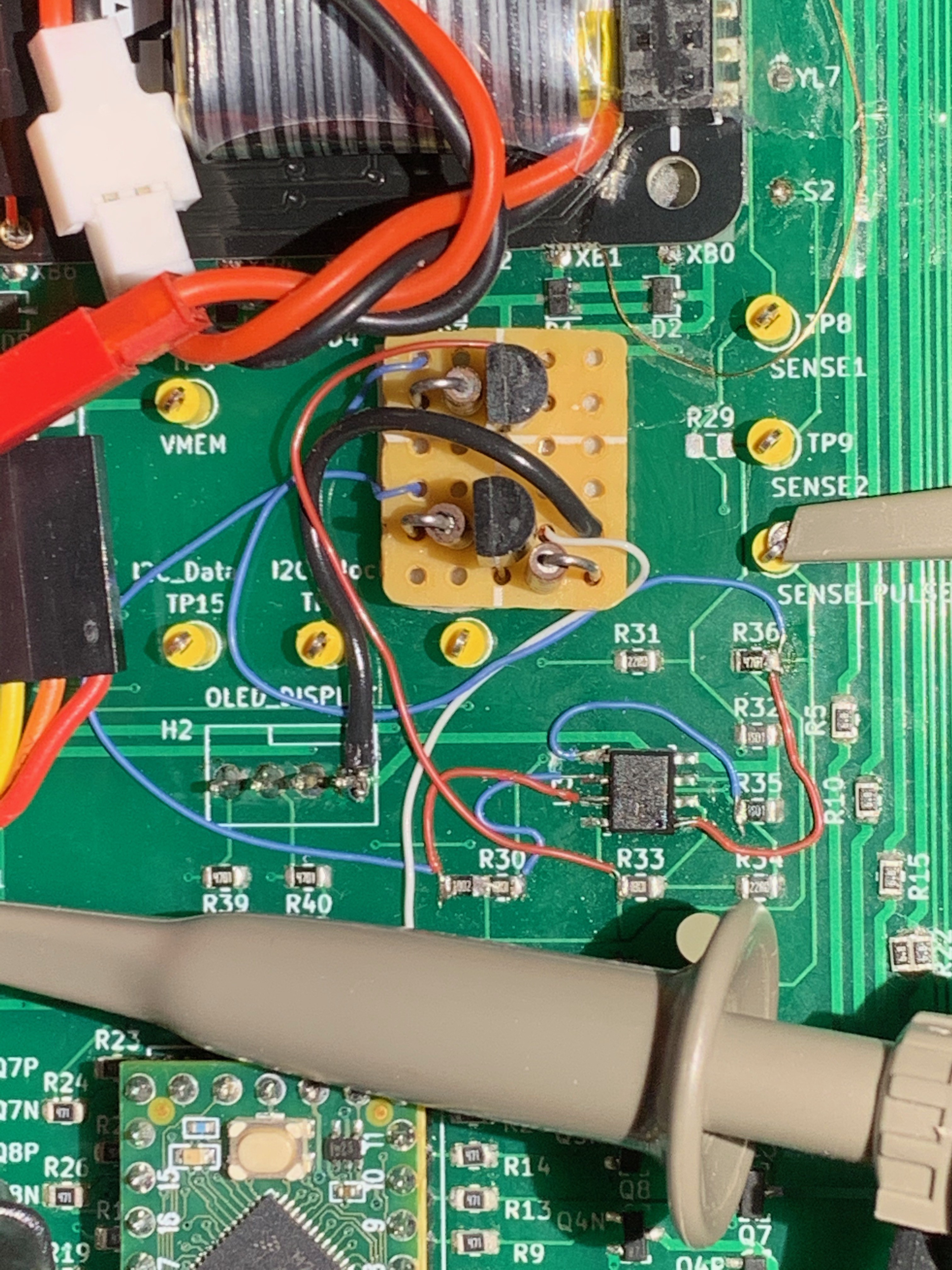
I spy a blue wire...
![]()
OK. Back on track now. The next step is to see if I can read the sense pulses and draw on the core memory screen! I am excited to see this come fully alive!
-
Core Sense Circuit Working Now!
01/31/2020 at 14:52 • 0 commentsIn my previous work, the cores were starting to come alive and the LEDs were showing evidence of this. But only some cores worked, and they were not lined up with the LEDs they were supposed to affect. This was evidence of multiple problems.
I began to suspect whether the LED array functions were mapped correctly to the LED positions. Since that is independent of the cores, I set out to resolve that issue and I have completed the API that allows interaction with the LED array. I have included test functions to confirm it works in monochrome or color mode, and can be addressed as either a series of 64 LEDs, as a matrix by X/Y position, and as a 64-bit binary value (which makes it easier to visualize the bytes by rows if numerical data is to be stored). Turns out the LED addressing was correct, although the API clean-up was a huge improvement. So if the LED addressing was correct, that might mean the core addressing was not correct. And now the LED Array HAL is above the LED Driver, but that's another story.
Now back to the hardware. I discovered and fixed two errors in the core polarity change sensing circuit (used for reading the bits). The first mistake I made was swapping the inputs to one of the op-amps used to sense core pulses that occur when a core changes polarity. The second mistake was a poor choice to skip the use of an OR gate to combine the outputs of the two op-amps. Yes, that's just an outright fail on my part. The result of those mistakes were that the core polarity changes were *sometimes* working That made bring-up... challenging... Here's the repair work:
![]()
At least everything was well labeled so it was relatively easy to blue-wire the OR gate in. Now the core polarity sensing is working, so I moved on to determining if the cores are working.
Indeed, the cores are working!!! That was an exciting step. And, because I was previously swapping some current setting resistors, that explains why some of the cores work (with more current) and some don't. I'll calibrate the resistor selection later, but the more pressing problem now is that the transistor matrix addressing logic needs some work. I failed to account for the alternating arrangement of the cores. They are canted left then right, alternating through the rows and columns. This is to reduce the number of drive transistors required, but the result is that the linear addressing of all the bits in nice rows was wrong-headed. I re-discovered that the odd and even bits are in different rows. I knew this before because that is how Jussi's Core Memory Shield worked, and I had to understand that mapping to make the LEDs line up. Now that I've re-learned this fact, I am updating the row addressing logic into a bit more complicated look-up table. The first five bits are now confirmed working and in proper order, counting from 0 to 4 in the upper left of the array. I'll expand the look-up table accordingly, and that should resolve the positioning of all the cores to line up visually. And then I can tweak the current drive resistors and get all of the cores working reliably.
Overall, major progress! Won't be long and I'll be drawing directly in the core screen memory.
-
Where are the electrons going?
09/09/2019 at 02:30 • 0 commentsDespite not posting an update, progress continues. I have written the low level core driver code to test setting and clearing bits, and am working on trying to detect the state of a bit. This has turned into a lot of time spent probing with an oscilloscope verifying that the current is flowing in the proper wire, in the proper direction, and with enough juice. And this is where the weakness of the circuit design has become apparent.
![]()
I've been able to sense some cores, but not reliably. I think there are three issues I'm dealing with:
1) Core/MCU voltage selection. The transistors are driven with 3.3V but the power from the battery is above that. When it is too high, half of the transistors aren't turning on like I expected, because of physics. Short-term I'll use an auxiliary 3.3V supply. Long-term, this design may require tighter voltage regulation for the cores, instead of taking whatever the battery has available.
2) Transistor Vce drop. The drive current capability of the MCU is very weak, and with the voltage drop of the transistors (three in series), there isn't much left to work with to magnetize a core. I'm seeing ~300mA for each half select current is marginal at setting cores. And increasing the battery supply voltage above 3.3V makes the situation worse because the transistors fail to switch around 4.2V, without an increase in drive current. Short-term I'm going to test darlington transistors and MOSFETs.
3) Sensing signal circuit. This may come down to biasing in the sensing circuit that needs to be tuned. Fairly consistently, I see the core is set in one direction or cleared, but then not in the opposite direction. This could also be because the drive currents aren't high enough because there is a difference depending on which direction the current is flowing. I can clearly see how the sense signal timing varies based on the current through the cores. It affects how quickly the core snaps to the opposite polarity. I'll circle back to troubleshooting this after I get #1 and #2 pinned down.
-
Documentation Updates
08/25/2019 at 03:09 • 0 commentsI created and uploaded several important files and updated the documentation today. You'll see PDFs in the "files" section of this project here on hackaday,io, and the similar updates in Github.
- Schematic
- BOM
- Code plan for reading and writing the cores
- Development plan
- Electrical Block Diagram
- Software Block Diagram
- Manufacturing Considerations
- And licensing and permissions analysis of everything I'm making use of
I also added an STL of the stylus, designed with Onshape.
And finally the code that has been updated to show the symbols on the LED matrix.
-
LED Matrix Control
08/22/2019 at 22:06 • 0 commentsI've succeeded in taming the LED matrix with the FastLED library. That's a new one for me. Because of how I chose to install the LED array, and how I'd like to depict symbols to be almost-human-readable in the firmware as a 2-D array, I had to rotate the image CW 90 degrees when translating from the "monochrome screen memory" array to the display. Here's what this progress looks like.
![]()
Hopefully that's recognizable... I need work on my shutter tech skills to capture the OLED without letting the electronic shutter mess it up.
I've begun implementing the core memory control, at the lowest level. I'm working on an approach that is flexible, but still abstracted enough to make it easy to follow the logic. This is one of the parts of the project that I think would be a highlight for someone wanting to get into the nitty gritty of core memory control schemes. Because none of the decoding is in hardware, you get to configure it however you'd like in the firmware!
Also had another eureka moment, maybe. I've been considering adding a few more magnetic features, since the theme of this project is fundamentally magnetism. I wonder if I can put in a small speaker and have it serve all of these functions, depending on how the coil is driven:
- Audio (in the human range and beyond)
- Vibration for haptic feedback
- Nearfield Magnetic Induction (NFMI) two-way communication between adjacent boards (send AND receive with the same coil)
I'll be chewing on that and experimenting in the near future to see how far that concept might go.
Oh, and I 3D printed a stylus with a small magnet on the end. It works well with the other 4x8 core shield, and I expect it'll work well for this arrangement. The cores are almost exactly twice as far apart now, which should make them more discretely controllable. In the other shield concept the magnetism from the stylus was fairly wide spread and would often affect cores outside of the one you wanted to control.
-
Prototype V0.1 Assembly Complete
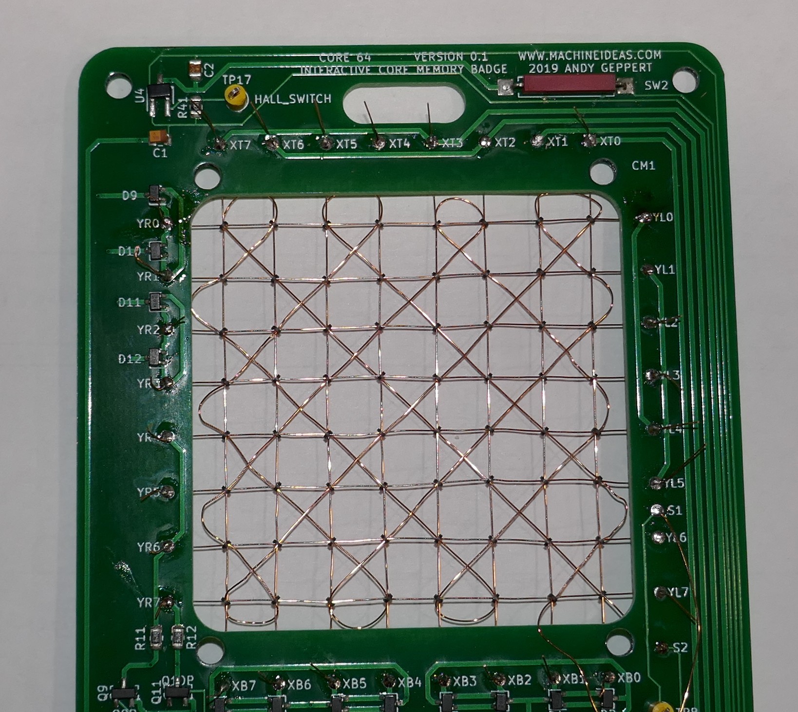
08/17/2019 at 21:11 • 0 commentsEverything is assembled [electrically] and ready for testing! The weaving process went fairly smooth and I was able to finish at a faster pace than I started. I took extra time to align and tighten the wires. And lots of time thinking about how these processes must have been automated back in the day.
*** Manufacturing Challenge Alert ***
I think the core weaving experience should be part of the project that the user does so they can get the full experience. And because I'm not sure this product can exist if I have to charge for the weaving work!
![]()
Some mechanical assembly remains to secure the LED array, but that'll come soon enough.
Core 64: Interactive Core Memory Badge
Weave your own Core Memory to learn and hack!