-
On to Blue POT Explorer
09/15/2019 at 18:18 • 2 commentsBlue POT has been running for some months and, it turns out, only a partial success. It works but there have been some glitches.
I live in the foothills of the Rocky Mountains so our cell phones have to use WiFi when at home since there is no cell coverage. My partner's iPhone seems to have a difficult time using both WiFi and Bluetooth when Blue POT is far away from the iPhone. It drops the WiFi calls. I theorize this is because the bluetooth system is struggling to move all the voice data and requiring a lot of on-air time and this interferes with the WiFi enough that it can't maintain a voice connection.
Hand wired Blue POT's poor EMI design also manifests. You can hear clicks whenever the Bluetooth radio goes on-air in the handset and those clicks are louder as the Bluetooth module increases output power.
Finally I have seen some cases where the Bluetooth module won't automatically re-pair with the phone so I suspect there is more code to be written.
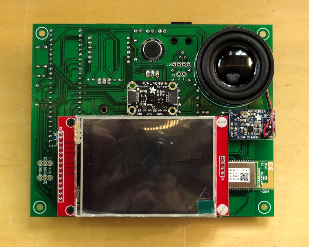
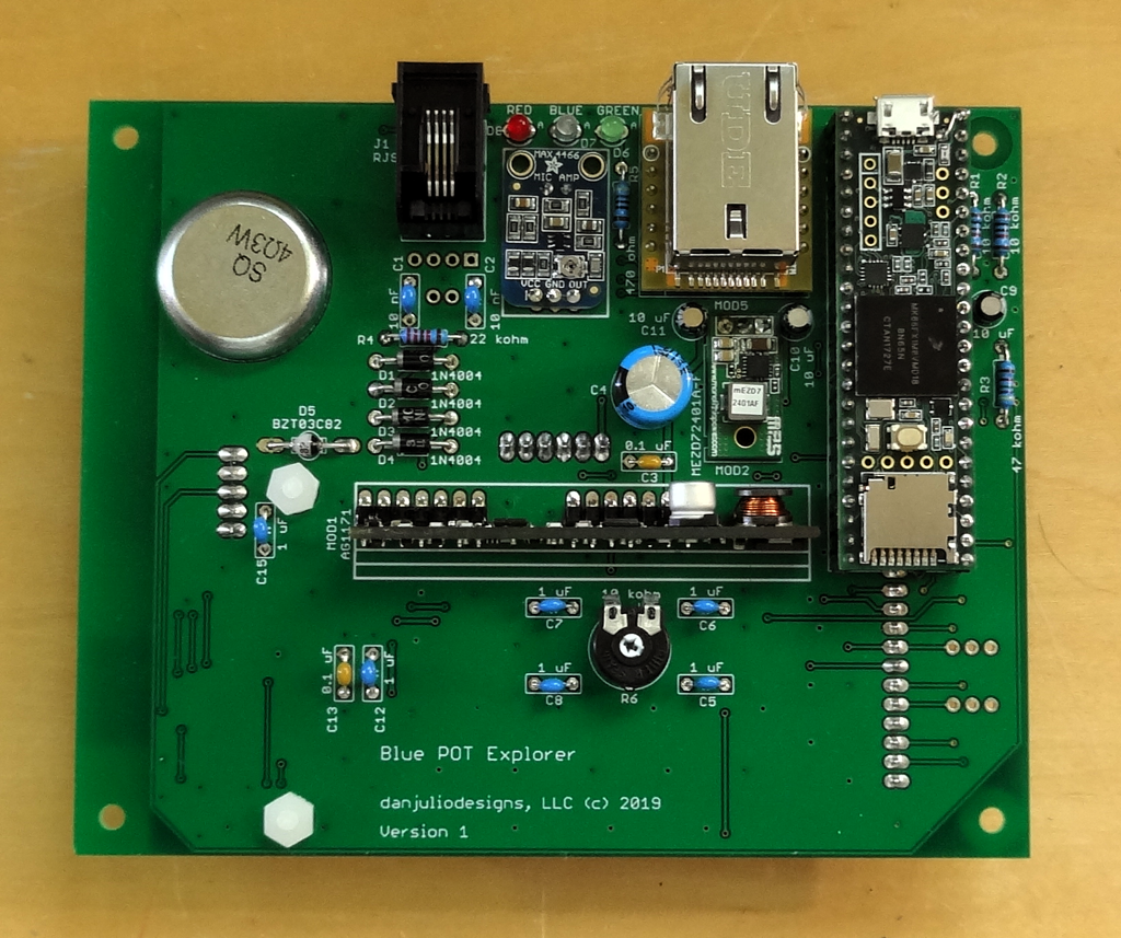
Introducing Blue POT ExplorerUndeterred by all that I have pressed on to an improved and more capable design I call Blue POT Explorer. I have PCBs now and am just starting to look at the code. Blue POT Explorer is designed to be a flexible platform for developing applications that use unmodified POTS telephones. It adds the following items.
- Move to Teensy 3.6 for increased processing power/memory and SD-card for storage of audio clips that can be played over the phone (imagine dialing a number to hear an audio clip).
- Touch LCD for a GUI for operation and configuration. I'm planning to use littlevgl for a multi-tile type interface (slide tiles left and right for various screens). A light sensor/proximity sensor should allow intelligent dimming and display content control.
- Local speaker and microphone connected to the 2nd set of built-in DAC/ADC interfaces on the Teensy 3.6 for speaker-phone and intercom functions.
- Optional Ethernet interface for applications like SIP VOIP or remote streaming. I'm hoping that the ESP32 WiPhone group will release their SIP code and I can adapt it for Blue POT Explorer.
Blue POT Explorer will be documented in a new hackaday.io project and the hardware and firmware will be open-source with a complete BOM and parts sourced from Mouser, Adafruit and Amazon. It's designed using through-hole parts and modules containing the SMT parts for easy assembly. The only hard part is soldering the BM64 Bluetooth module and that's not too difficult.![]()
![]()
-
The BM64 Bluetooth Module
07/09/2019 at 04:40 • 2 commentsWhen I started this project I looked at the RN-52 and BC127 Bluetooth audio modules available at Sparkfun. Some of the comments on the BC127 page made me a little wary of this device and the RN-52 is getting a little long-in-the-tooth so I decided to look at other audio-capable Bluetooth modules. A search led me to the Microchip BMXX family that are more modern and significantly less expensive (less than half the price for a high-power model and about a third of the price for a lower-power model). Although it's clear that this family of modules is aimed at stereo headsets and speakers, they also support telephony applications. I bought one without diving into the specs. It all worked out but the BM64 module is not without its complications.
Microchip acquired Taiwan-based ISSC for their Bluetooth technology. The specification and user manuals for the modules are translated to English and pretty basic. Although they are good at explaining the binary protocol implemented by the serial interface, often it isn't clear what the commands actually do and some features such as the "database" specified in some commands, of which there apparently can be more than one, are not explained anywhere. I was quickly able to to talk to the module but getting it to do what I wanted took quite a bit of experimentation.
The serial command set is pretty large and broken into two parts, one of which is declared as depreciated but necessary for telephony functions. Not all module configuration can be done through the serial interface while the module is functional. One has to download a development environment containing eight Windows applications that are used to configure the module. The most basic process consists of running the "UI Tool" to configure module behavior, the "DSP Tool" to configure it's audio functionality, the "MPET Tool" to merge the UI and DSP configuration files and the "EEPROM Tool" to write the merged data to the module. Through trial and error, I found that I had to makes changes to the module behavior to make it amenable for use as an always powered-on handsfree telephony device as opposed to a battery-powered Bluetooth stereo speaker. I made no changes to the DSP configuration. My customizations are found in the "bluePOT.ipf" file in the github repository. This is the combined file and can be directly programmed using the "EEPROM Tool". The process of using the software tools is documented in the evaluation board user's guide. Programming occurs through the module's serial port with it put in a special mode at reset. Blue POT supports this with a jumper that will turn the Teensy into a USB UART at power-on and configure the BM64 for updating. The Microchip/ISSC EEPROM Tool opens Blue POT as a com port. The BM64 module must be configured with the "bluePOT.ipf" file in order for it to work with the prototype Teensy firmware.
Ultimately I used a small subset of the serial commands to initiate calls, answer calls and cancel/hangup calls; and process just a pair of event notifications from the module (module status and call status). The prototype code simply captures these individually but it would probably be better to make a generic driver for the module handling all commands and events to keep a complete state of the module.
One complication came about after I gave the Blue POT as a gift to my partner who uses an iPhone (I used an Android phone to test). There were a few differences in the way the two phone architectures communicated events and dialed that caused it to fail right away with the iPhone. One difference I remember is that the default volume the iPhone sets in the BM64 is too low, The code has to manually tell the BM64 to use a high volume after a call is established. Fortunately these were easy to overcome and seem backward compatible with Android. I imagine that there are other issues still remaining with other versions of Android and/or IOS. I can only imagine the number of phones that car manufacturers have to test their Bluetooth integration with.
I used the BM64 but the BM62 is another, less expensive, possibility. The BM64 has more features including an I2S serial audio interface. Theoretically it can connect to the Teensy I2C port through the Audio Library but I think that the BM64 reverts to an 8 KHz sampling rate for telephony that can't be handled by the Audio Library.
The BM64 can store up to eight Bluetooth pairings but only automatically connects to a phone using one of the pairings when it is first powered on. This is a problem if the phone comes into range after the module has been powered. It's possible that there is some EEPROM configuration to enable additional reconnect functionality but I couldn't identify it, so Blue POT code stores the current pairing number in EEPROM (Pairing ID) and requests it to attempt to connect with the specified pairing once a minute while the BM64 reports it is not connected. This ensures that the telephones become functional quickly when the cellphone comes into range. The first cellphone paired is "0", the second cell paired is "1" and so-on up to the eighth cell at Pairing ID "7". Blue POT shows up as "Blue POT" during discovery and pairing.
-
Teensy Control
07/06/2019 at 16:57 • 0 commentsIt is Paul Stoffregen's fantastic Audio Library that drove the choice of the Teensy 3.2 for control. I had seen his DTMF decoder example and I knew that it should be able to easily generate the tones for the phone using the library's sine-wave generators. I figured the rest of the logic would be well within the capabilities of the Teensy and it is. The built-in ADC and DAC signals can be used so there is no need for an external codec.
![]()
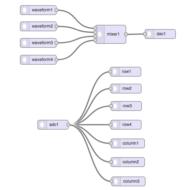
The system is comprised of two independently operating halves. An output stage combines up to 4 waveforms and an input stage uses seven tone decoders to detect the DTMF tone pairs (the cross between row and column decoders indicates which button has been pressed).
The system currently generates three output tones using 2 or 4 of the waveform generators.
Tone Freq 1 Freq 2 Freq 3 Freq 4 Dial Tone 350 Hz 440 Hz - - No Service 480 Hz 620 Hz - - Off Hook 1400 Hz 2060 Hz 2450 Hz 2600 Hz The No Service tone (pulsed) is used to indicate there is no Bluetooth connection when the user picks up the receiver. The Off Hook tone (pulsed) is used to indicate the receiver has been left off-hook for more than 60 seconds. The Bellcore standards specified power levels for each tone but my system makes no attempt to match these. It drives the maximum level out of the Teensy that was sufficient to drive the input of the AG1171.
The DTMF decoder is straight from the Audio Library example with an approximately 30 mSec detection window for each of the seven frequencies. DTMF was designed to be an in-band signaling technology, meaning that the tones travelled along with the rest of the audio. In fact there is an interesting history to read. DTMF is still used today in various other signaling systems.
I found one bug (at least on my old version of the library that I currently have loaded). The PJRC Node Red Audio Editing tool generated code that put the DAC object instantiations first followed by the ADC objects. The ADC didn't work until I reordered the object instantiation with the ADC side first.
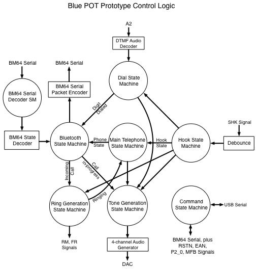
The system is controlled through a set of interlocking state machines. This architecture works very well although it essentially came into being because I was slowly gaining experience by building one function at a time. State machines share state and events as necessary but only perform one function. The telephone-related state machines evaluate every 10 mSec (primarily for debouncing the switchhook signal). The Bluetooth state machine evaluates every 20 mSec. The Command state machine evaluates as serial data arrives from the host.
![]()
The Bluetooth State Machine is the system master and coordinates between the Bluetooth side and the telephone side.
-
Following in Anders' footsteps
07/05/2019 at 17:58 • 0 commentsHa! Anders Nelson already made his own version of the Blue POT using a PIC32, RN52 and the AG1171 - over 4 years ago. And somehow I didn't come across it doing research when I started this project. Check out his design at his github. Interesting to see how he solved some of the same problems.
And admire the phone he put back in service for his cousin!![]()
-
A FXS with a SLIC and other historical things
07/04/2019 at 18:36 • 0 commentsThis log entry is ultimately about the circuit I use to interface to the analog telephone line but there is some fascinating history behind this part of the design.
Blue POT's deep roots
Voice telephony is about 170 years old at this writing. The first few decades were like the early days of micro-computers with lots of innovation and lots of different, incompatible, systems. This page has links to many articles detailing various historical aspects of telephony if you are interested in digging in further. Research I did shows that the origin of technology that Blue POT implements in 2019 first appeared over 130 years ago. Talk about backward compatibility...- The names "Tip" and "Ring" that are still applied to the Green and Red wires in a twisted POTS line came about in the early 1880s as part of a plug used to connect calls in manual switchboards. The Ring (outside) is held at a negative potential to the Tip that is near ground potential. This was to prevent cathodic corrosion in long wire runs.
- Bell ringing voltages and cadences, originally generated by a customer cranked magneto, were put into service around the same time (80-100 VAC at 20 Hz). Over time this voltage became somewhat standardized although rural telephone exchanges often drove a higher signal (up to 150 VAC for party lines) to accommodate the long distances.
- The "Common Battery" system providing power at the central office first made an appearance in 1888 although the voltage levels that were finally standardized on by Bell in the USA, along with impedances, around the turn of the century. The -48V bias voltage we know today was based on 24-cell lead acid battery technology (nominally 52.1 volts at the central office).
- Although the first patent for a rotary dial was granted to Almon Brown Stowger in 1892, and there were some even earlier automated dialing systems, the rotary dial we know today made an appearance in the early 1900s. Fun fact: because it takes a lot longer to dial a 9 than a 1, Bell assigned the long-distance 3-digit area codes based on usage (the most frequently dialed areas got the quickest dialed area codes).
- The rotary dial reigned supreme for almost 60 years until the introduction of DTMF (dual tone multi-function) in 1963 although there were earlier telephones using keypads that converted button presses to pulse sequences simulating a rotary dial.
So you want to simulate a telephone line
I knew a few basic technical details about analog telephony when I started and figured I'd just hack something together that would work "well-enough". As a kid I saw an experiment where two phones were connected with a 6 volt lantern battery in series to provide enough power to talk. I also knew people successfully rang telephone bells with all kinds of voltage levels.
Initially I looked at circuits like this one and others that used discrete circuitry to interface the analog voice signals and impress ring voltages onto the line. However since I was going to hand-build the unit (at the time I thought I'd only make one) I was put off by all the wiring.
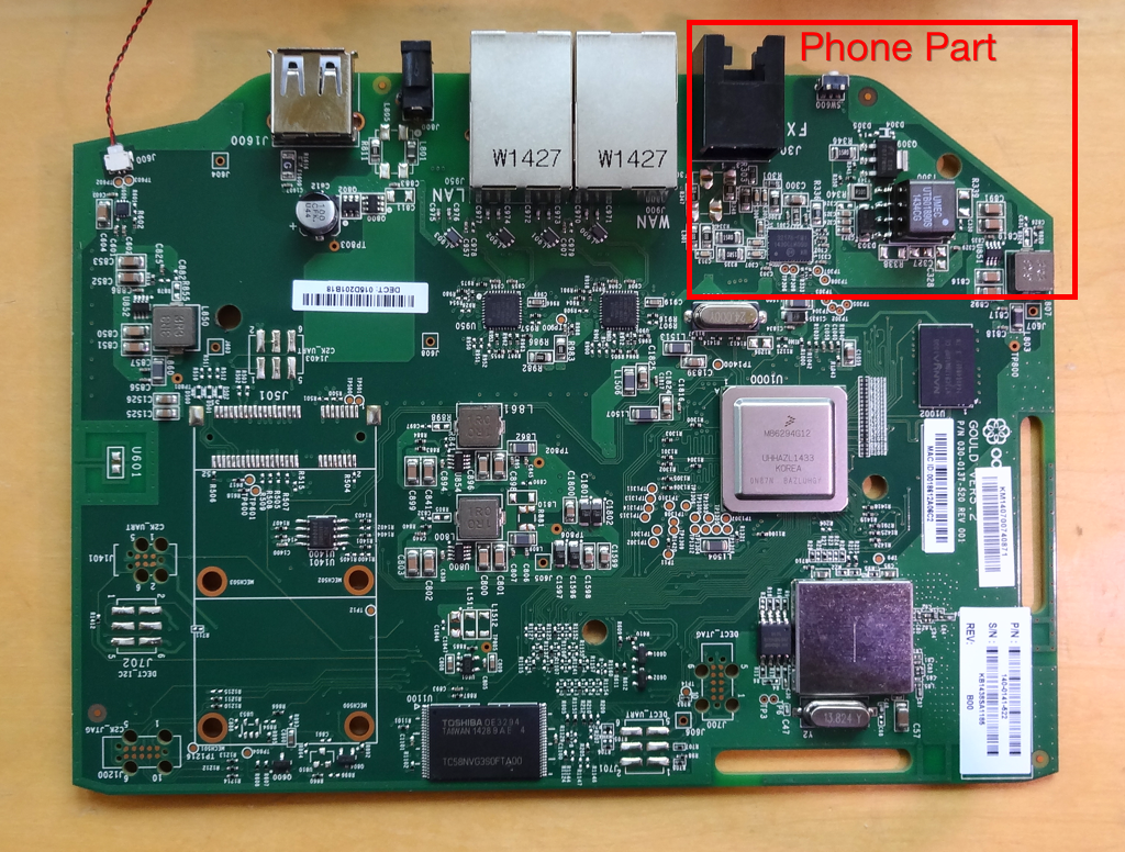
For my business I have kept my old landline phone number ported to Ooma's VOIP service and at some point realized that I had a telephone interface literally sitting on my desk. A few turns of a screw driver later and the Ooma - essentially a router that thinks it's a phone - lay apart in front of me.![]()
This lead me into a world of new terms such as FXO, FXS and SLIC and the contemporary technology that implements them. I was going to design a FXS (Foreign Exchange Station - or Central Office) using a SLIC (Subscriber Line Interface Circuit).
More research ensued, starting with thinking about an ancient design from Motorola that was pretty straight forward but using more-or-less obsolete silicon to modern solutions from companies like Silicon Labs and Renesas aimed at VOIP solutions like the Ooma. These chips include codecs with serial interfaces and require external switch-mode DC-DC supplies to generate the telephone line bias and ring voltages. There are people who have successfully used them but they bring their own complexities to the table and some, like the Silicon Labs chips, seem to have documentation that exists only behind a corporate firewall. Although by this time I was convinced I wanted to build a proper telephone interface, at least for use on-premise, I was less enthused about the design because of the work now needed.Along the way I had also seen some modules that appeared to have been used on line cards in central offices or PBX systems such as the Mitel HM88615. They incorporated circuitry to handle switching voltages and matching impedances to the telephone line. Initially I discounted them until I happened across the Silvertel AG1171. It was exactly what I wanted and at $6.07USD almost too good to be true - but it *is* the module you need if you want to play with old telephones, even if you only want to ring the bell, use the dial to control something else or deal with audio from the handset.
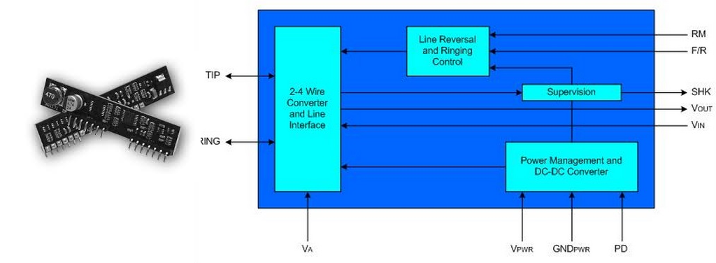
The AG1171SThe AG1171S is a 14-pin SIP and provides a complete interface, sans protective circuitry, to a phone line. It runs off 3.3-5V at less than 500 mA ringing a phone. It provides analog audio input and output signals, generates a -48V bias voltage and a -72V ring voltage, and detects the switch hook position (and rotary dial pulsing). It has 4 logic-level control signals (one is a power-down signal that I am not currently using). Super simple to use.
![]()
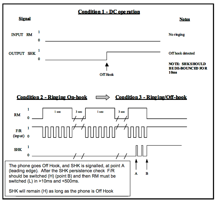
Two signals control its telephony function. The RM signal selects what voltage it drives onto the phone line. Normally it drives -48 volts to bias the line. RM is asserted during ringing to increase the voltage to -72 volts. Then the F/R signal is toggled at the ring rate (typically 20-25 Hz in the USA) to cause the bell to ring. The SHK signal is asserted when the switch hook is detected off-hook and toggles during rotary dialing. All illustrated in a figure from the specification below. Incredibly simple.
![]()
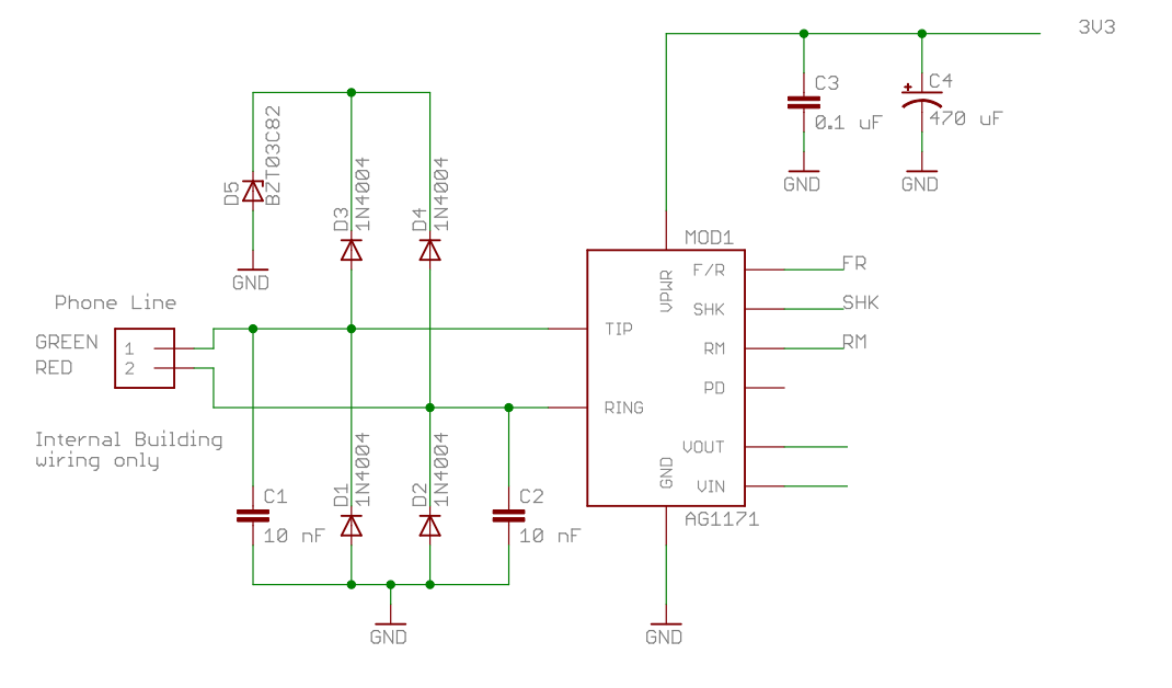
The AG1171 is designed for short loop "on premise" applications as opposed for use by a telephone company in their central office driving thousands of feet of line - in other words for devices like Blue POT. It does require some external protection circuitry. I implemented the circuitry recommended for ESD and EMI protection. The diodes shunt high voltages to ground or to an 82V rail provided by the zener. The capacitors reduce EMI. Apparently Silvertel has some documentation available for use with longer lines but I haven't looked at it.
![]()
All that's needed for interfacing with your old telephones.
Decoding rotary dialing through switch-hook pulsing and the analog interface will be discussed in other logs.
Blue POT
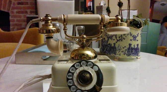
Yet another Bluetooth to Plain Old Telephone adapter. This one drives existing phone lines so you don't have to modify the phone.
 Dan Julio