-
1Start by the shorter components
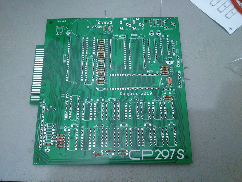
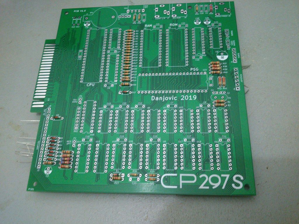
First components to be soldered on the board should be the ones that are shorter in height.
Start by the resitors.
![]()
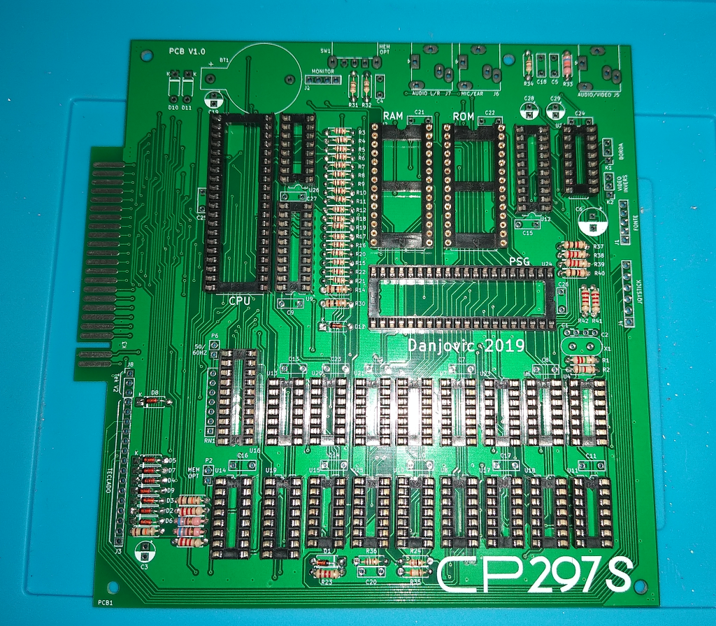
Then add the diodes
![]()
-
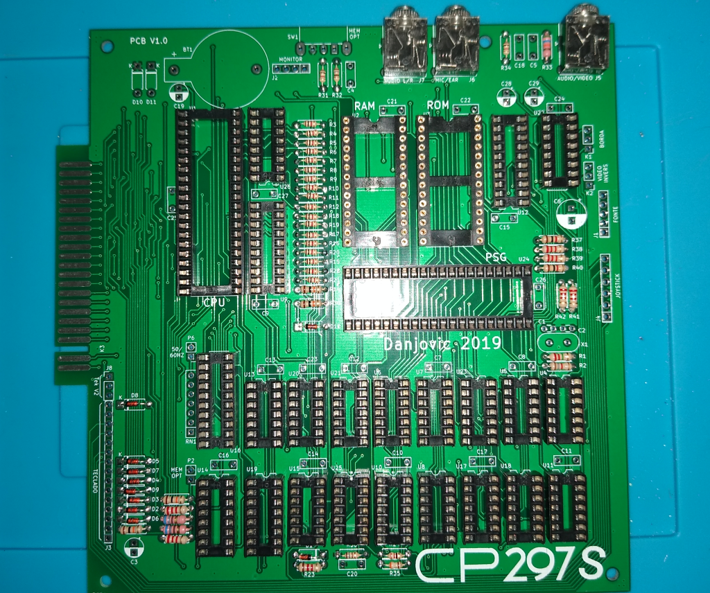
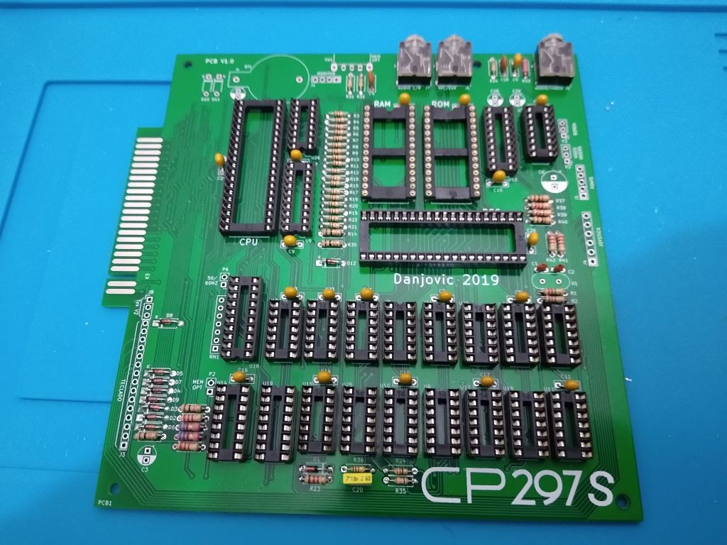
2Then add the IC sockets
![]()
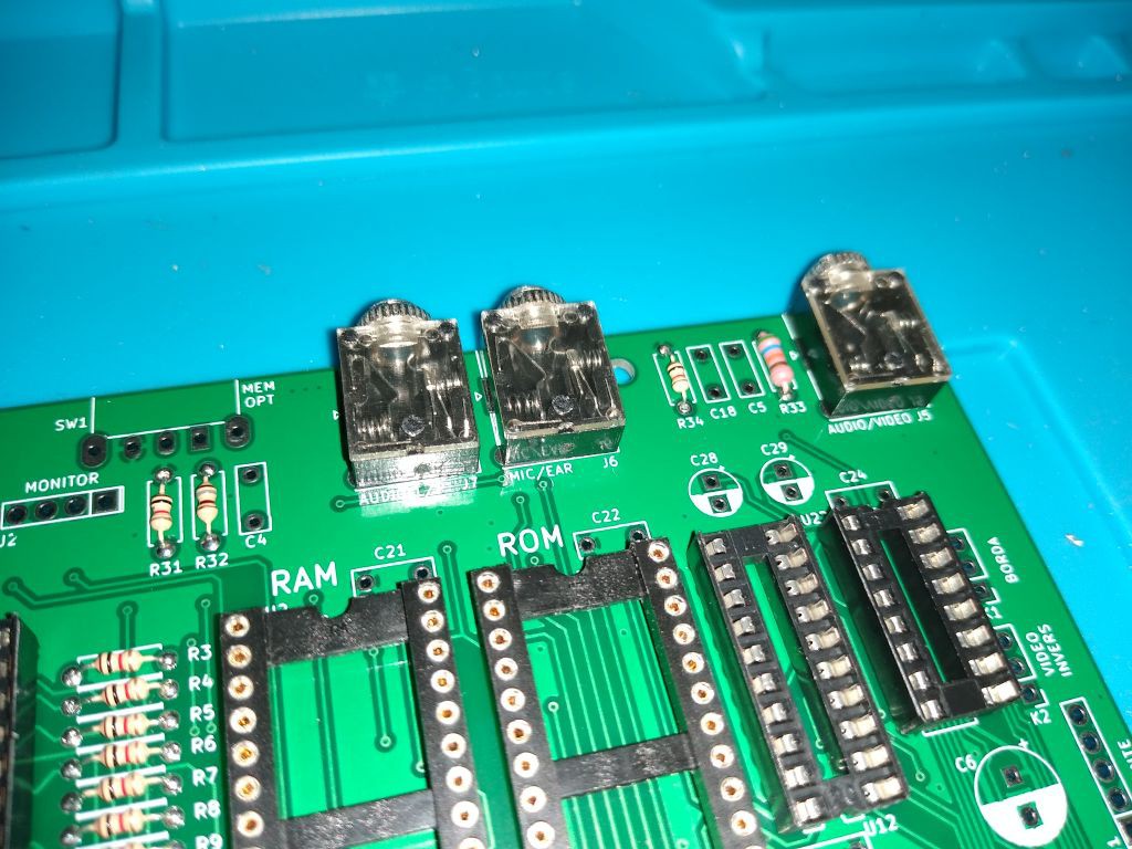
And solder the P2 Jacks
![]()
![]()
-
3Next solder the capacitors
First the ceramic and polyester capacitors
![]()
Followed by the electrolytics
![]()
-
4Add some headers
Add some pin headers, specially the Power Supply header
![]()
-
5Plug the PSU and perform some tests
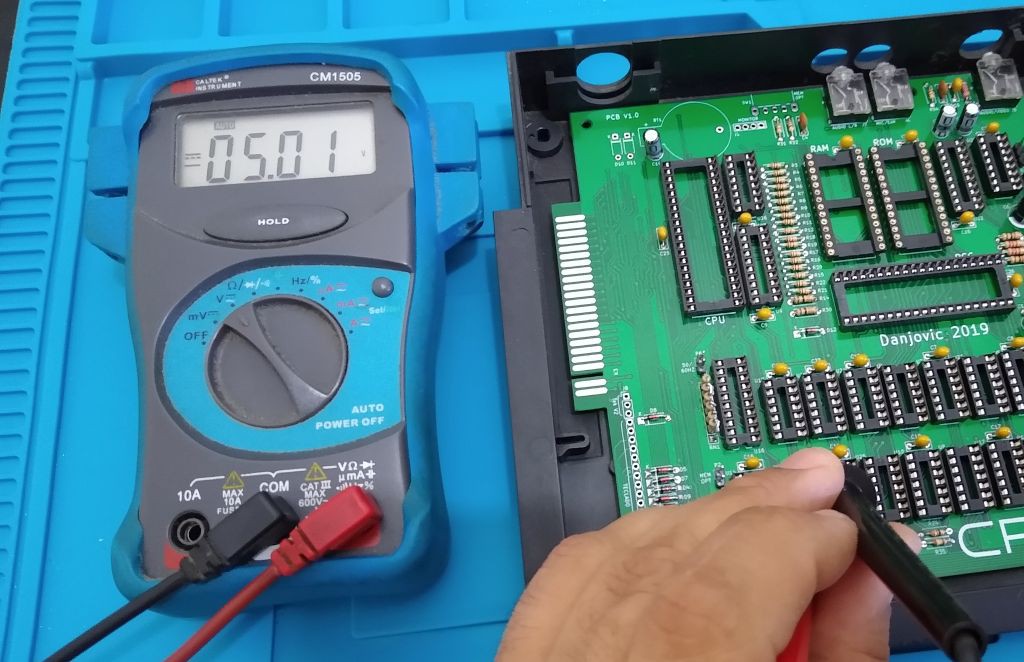
Plug the PSU to the board and test for the correct voltage (5V) at all IC sockets.
![]()
-
6Test the clock
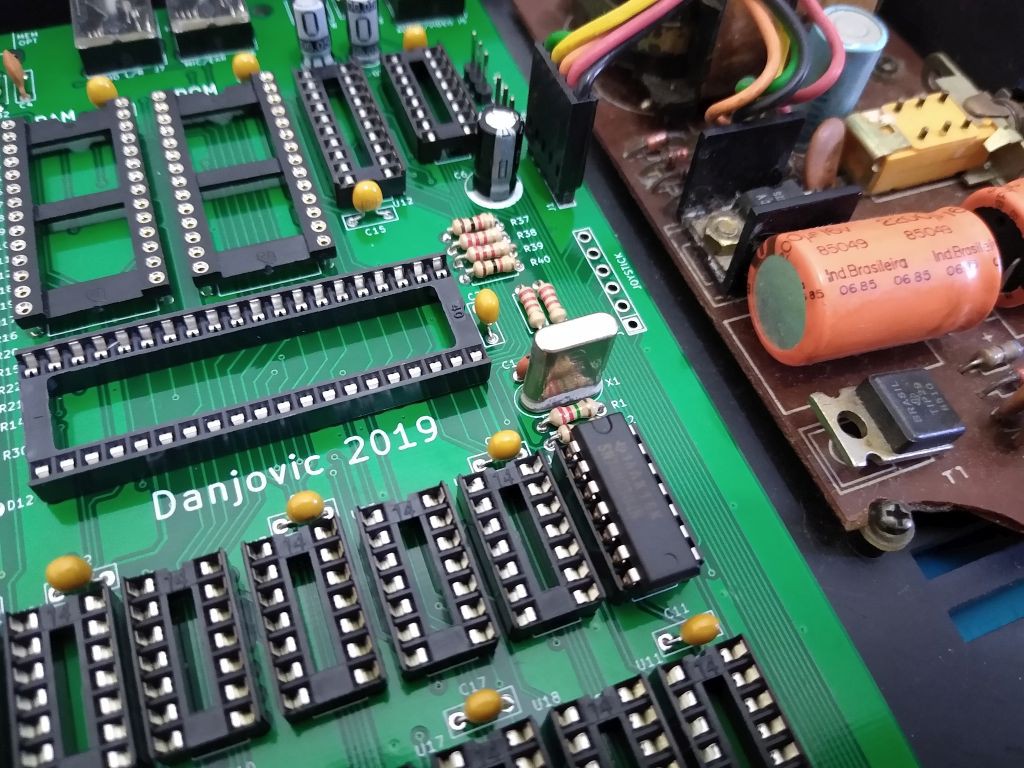
Solder the Crystal and insert U4
![]()
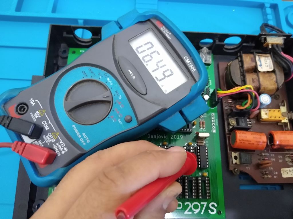
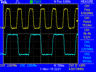
Power the board and check for 6.5MHz signal at pin 3 of U4
![]()
-
7Test the frequency Divider
The frequency divider is It is one of the few pieces of ZX81 video generating circuit that run standalone (mostly).
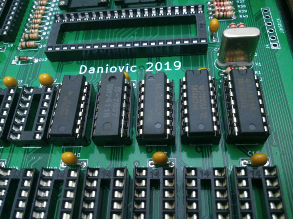
Insert U5, U6, U7, U23 and place a jumper wire from pin 2 of U23 to ground.
![]()
![]()
Then check for:
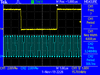
3.25MHz at pin 1 of U6
![]()
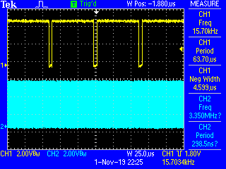
A Negative going pulse of 4.6us (Hsync) at pin 6 of U4 . The HSync frequency shall tick at 15.7Hz.
![]()
![]()
 danjovic

Discussions
Become a Hackaday.io Member
Create an account to leave a comment. Already have an account? Log In.