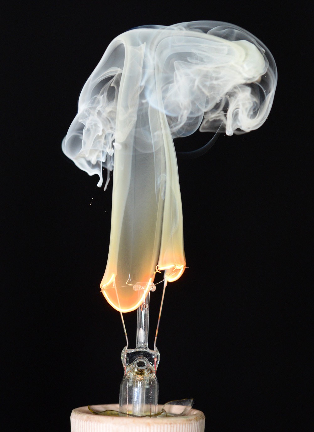
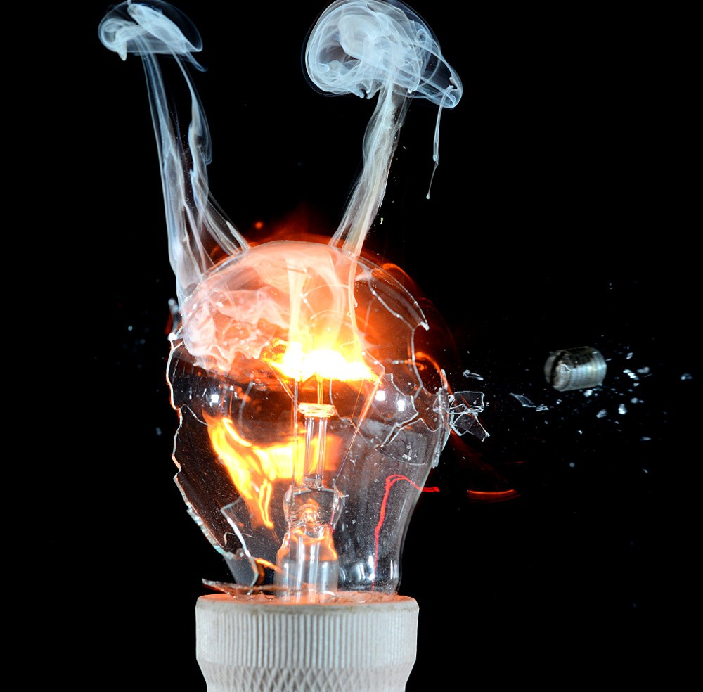
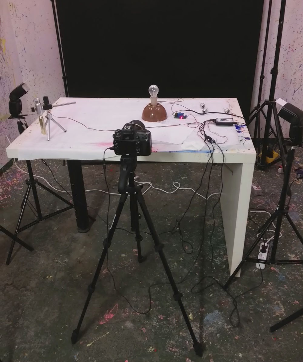
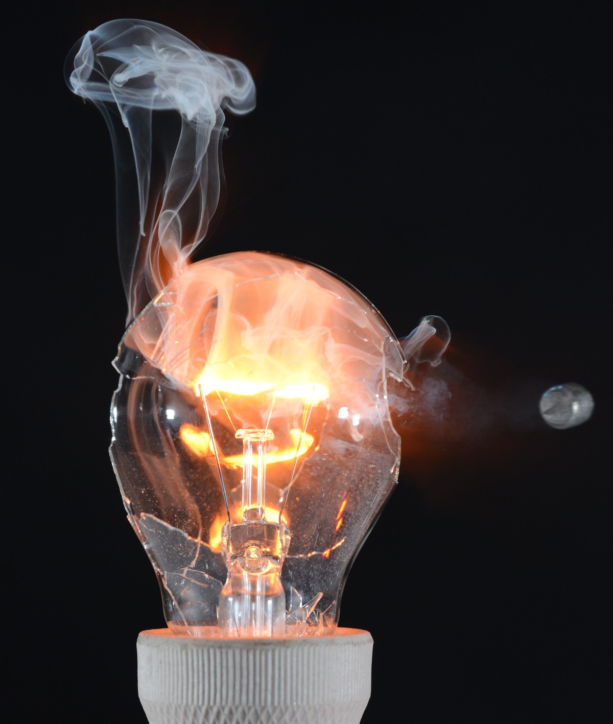
-
Contest entry video
09/30/2019 at 18:33 • 0 commentsHello I published contest entry video for this project and in this log I wanted to share some lessons learned and challenges which I faced during creating it:
Idea:
This was the easiest part as I already had an idea for such clip from quite long time ago and actually first attempt was done when I started this project entry and now idea remains same, but this time main objective was to make it best as I could. Mentioned attempt gave me some clues what challenges I can expect this time and I prepared better but still there was some challenges to be faced.
Here you can see this mentioned first attempt which was published with project entry: https://www.youtube.com/watch?v=cK5UgD781-4
Technique:
Same as previously photos needed to be taken not in high speed-photography method as this requires dark-room to be used and due to that I wanted to create video at same time it was not an option, so rather I needed to go opposite way and use high shutter speed and constant high power illumination. This approach has some downsides such as limited motion-freezing properties and shutter lag(explained further later in this log).
![]()
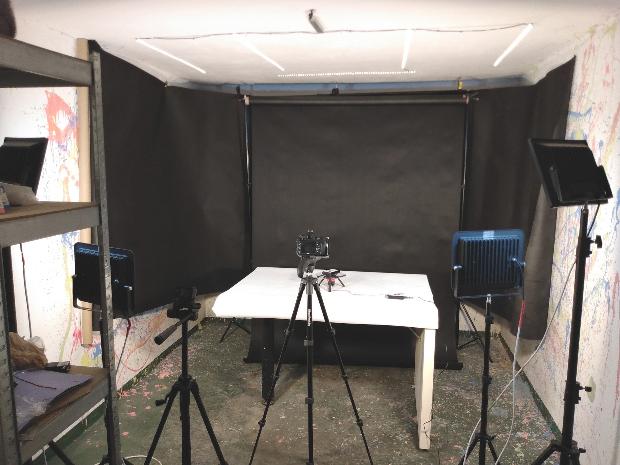
Setup for this video in my basement, during taking intro with turntable, but first I really had hard times to fix this background well :p Equipment:
Most of parts was filmed with Sony RX0 camera, as this is only camera(at least from what I know) in affordable price range on market which can shoot at such high frame rate which I needed to create this slow motion shoots. This camera is capable to catch up to 1000 frames per second(for very limited duration). As can be expected at such frame rate's quality need to be sacrificed and I already knew that at 1000fps(40x slow-motion) quality drop is very significant, so for first attempt I used 500fps(20x ), but this time I still wanted to get better quality so this time I used 250fps and i find it good decision as it gave me quite decent quality and satisfying slow-motion(10x) shoots. Additionally at such high frame rates shoot duration is very limited and for 1000fps it's just about 1 second, 500fps ~2second and for 250fps ~4-5 seconds, so I thought it will be handy to have possibility to trigger recording in right time... aand hmm this sound like something that I can do and I came with quite nice solution to use on of PiXPi's flash ports(as one is occupied by DSLR) as trigger for recording and i was quite supprised to found that it's working very well :)
![]()
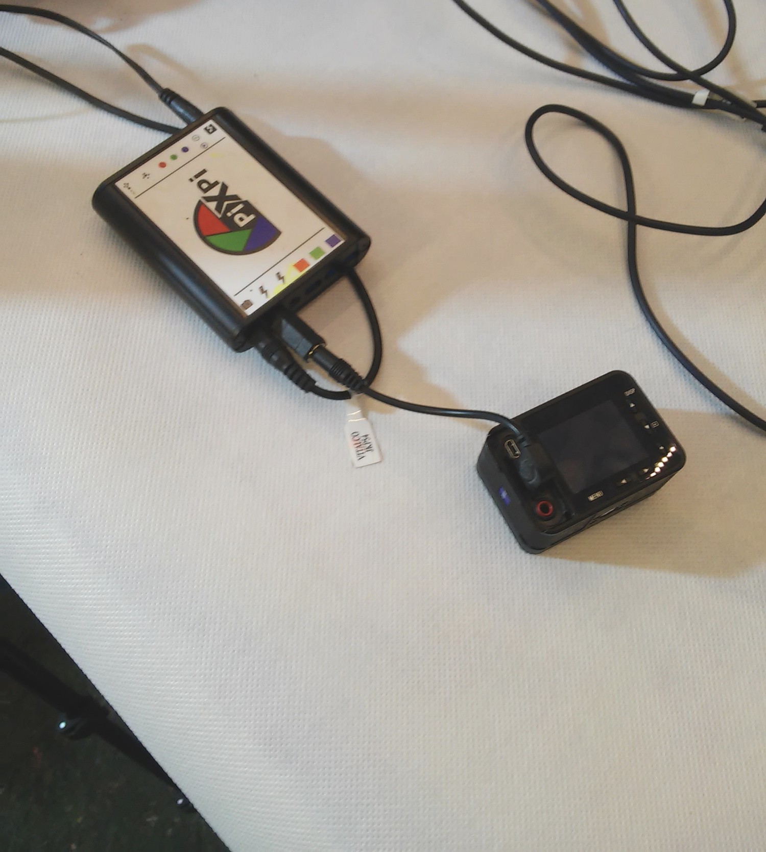
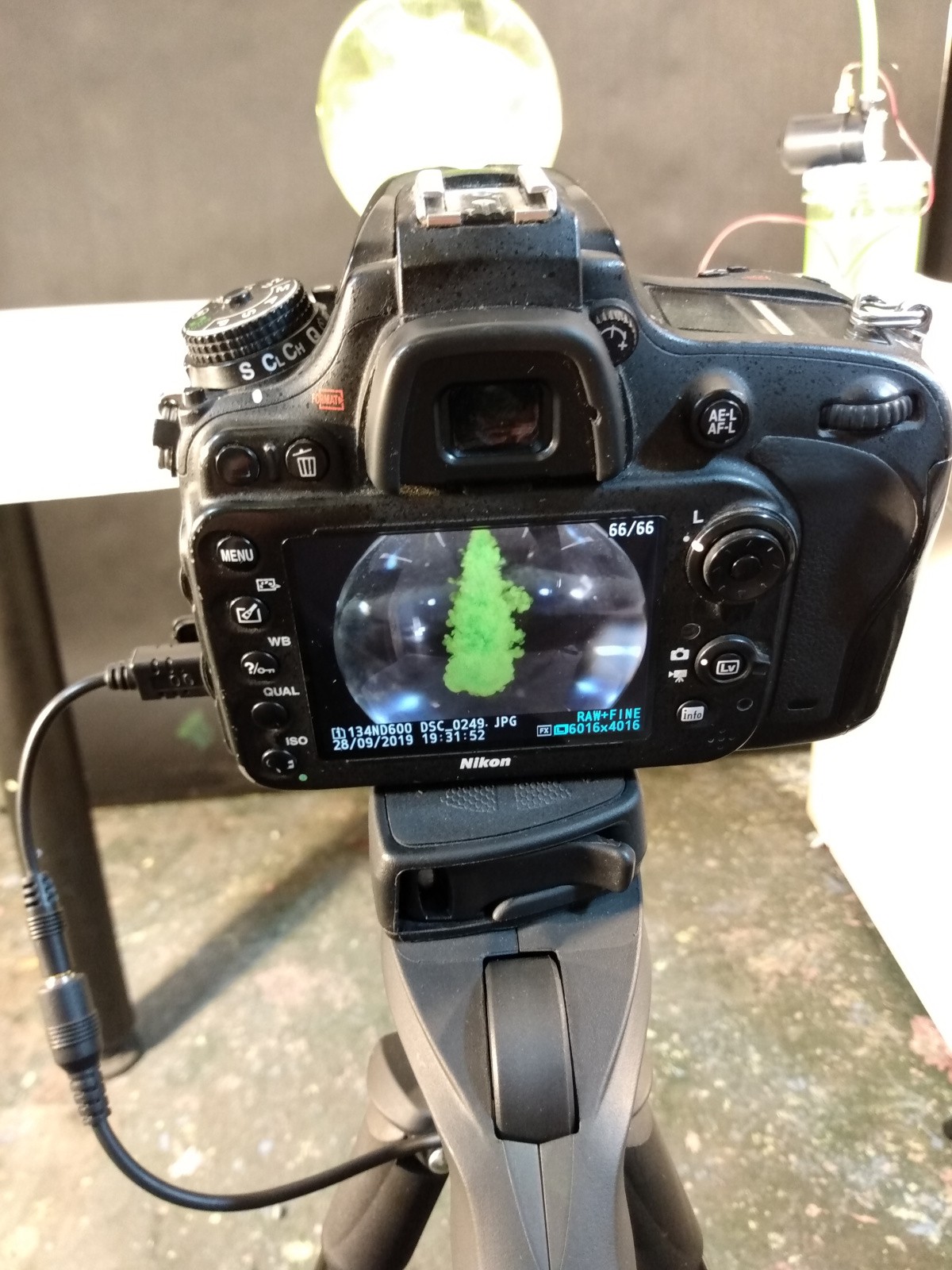
Sony RX0 camera connected to PiXPi's flash port for triggering, just 3,5mm/2,5mm jack adapter was needed I felt like winning on lottery when i found it working very fine, it was really helpful and I don't even need to change anything in app as I just used flash block to trigger this cam. Photos and some parts of video was taken with Nikon D600 coupled with 90mm Tamron lens, as this is only which I own. Shutter speed in camera was set to 1/4000-th which is maximum for this model, it could be better, but it was significant. 90mm lens forced me to push camera quite far from scene, so you will not see much of camera in video frame, but at least it is safe from hitting with some paint splash.
![]()
Illumination:From previous attempt I already knew that CFL bulbs commonly used as constant light sources in photography filmed at high frame rate give some significant flickering, due to mains AC supply voltage.
This time I don't wanted to see this flickering effect so I decided to give a try with led illumination, exactly budget Chinese spotlights, so in total I bought four of them, 2x quite cheap 200W with cold white light and 2x still quite cheap, but bit better quality 150W with warm white light...
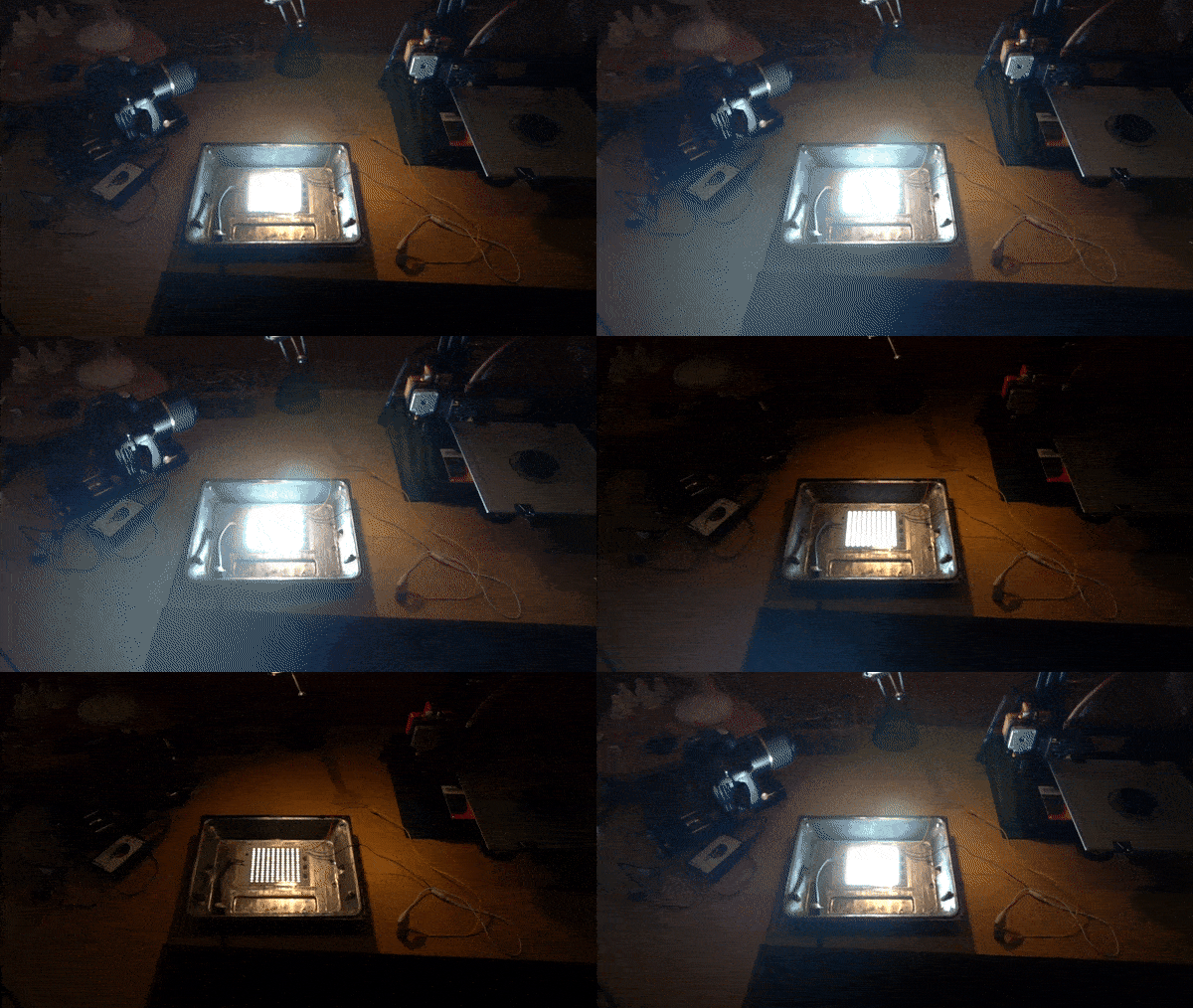
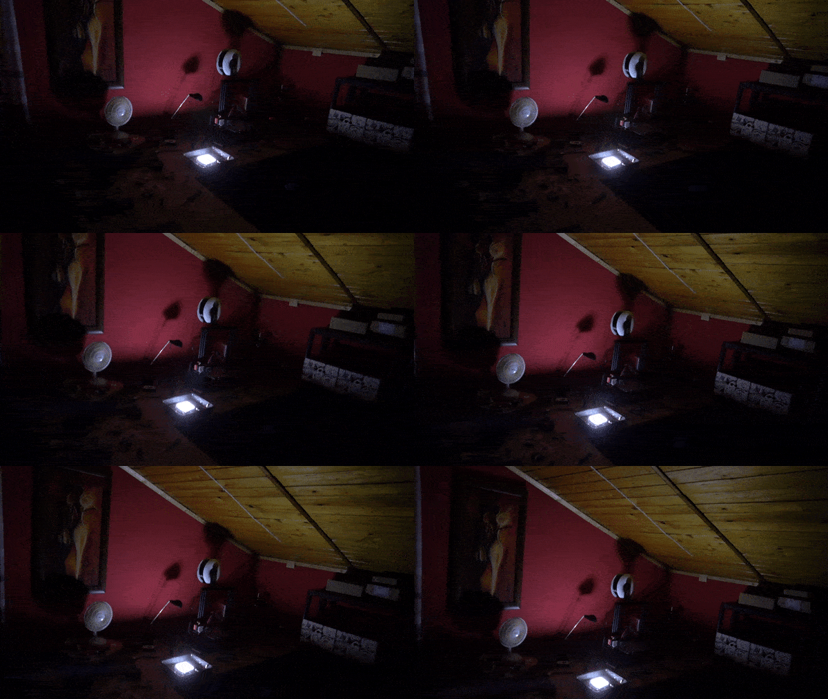
But this is what I saw when I filmed them at 500fps:
![]()
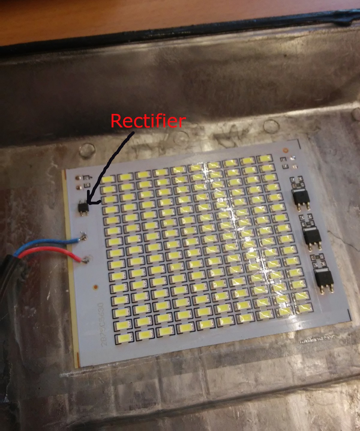
Assumption that cheap led spotlight will not produce flickering was naive ---------- more ----------At this point I was really upset, but as you can see on gif above I already decided to disassemble them and see if I can help something on this, at this point i regret buying those more expensive ones as they was glued with silicon and those cheaper was assembled with screws, but anyway this is what I saw after disassembling this 200W one's:
![]()
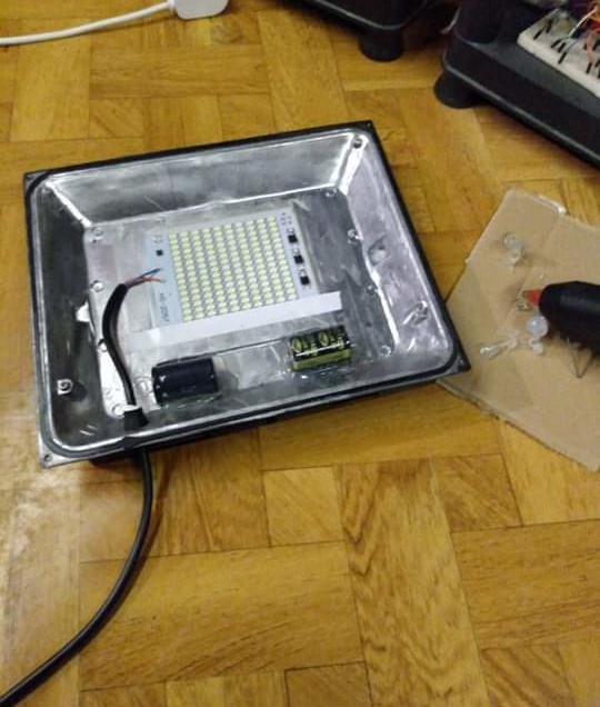
something is missing here I realized that AC is fed to bridge rectifier chip and on output of this there was no any smoothing capacitor, so I decided to mount some and see if this make some change, I expected some, but I was not sure how much it will reduce flickering effect:
![]()
2x220uF was added and fixed with some hot glue And again I took video at 500fps and this is what i saw:
![]()
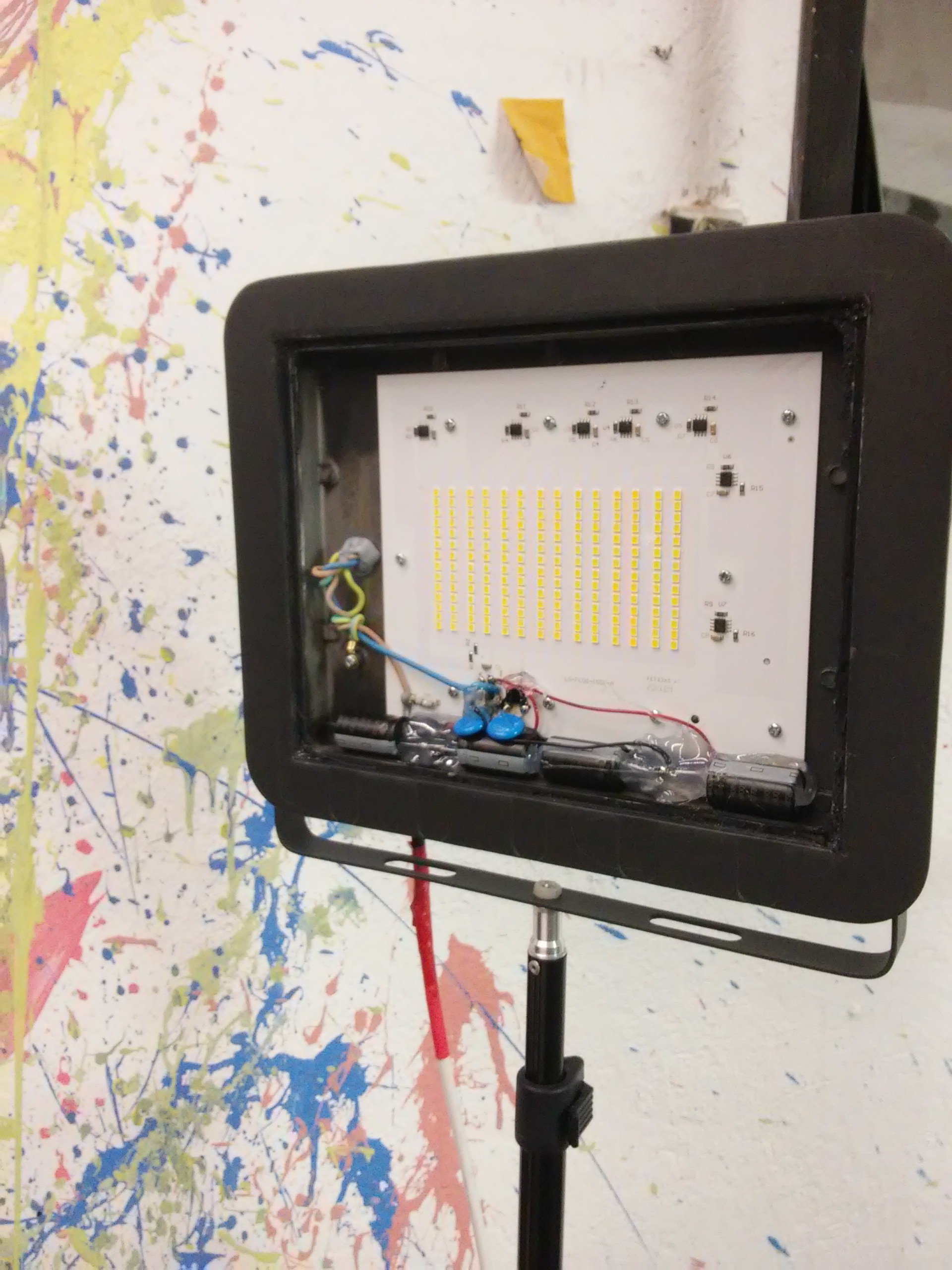
With capacitors flickering was totally gone :D I couldn't believe my eyes but flickering was totally gone I expected rather to reduce it but it was perfectly still now! So i quickly did this modification to other 3 spotlights, it was bit more challenging for this 150W one's which was glued with silicon and in result I ended with breaking covering glass, but i don't care much:
![]()
Quite dirty hack but did it's job, here I put 4x100uF capacitors Shutter lag:
Last difficulty which I got was shutter lag, as I needed to freeze motion with shutter instead of flash, due to that I created video at same time. There was problem that shutter reaction time, so time between sending trigger signal and actually taking photo is about 50ms, this time is called shutter lag.
Because of this I got quite big difficulty when trying to create two shoots in presented clip, this with popping balloon and this with crashing bulb with hammer, if you look carefully you will not see flash firing there.
Problem comes from that with this method minimal gap between detecting signal and taking photo is ~50ms which comes from this shutter lag and after 50ms this was much too late for this particular shoots to catch something interesting, so I needed to cheat a bit there and actually this photos which was shown on movie was taken with same setup but in darkroom with high speed method which gives almost no delay between detecting signal and actual shoot(as then flash is triggered instead of shutter).
Post-production/creating clip:
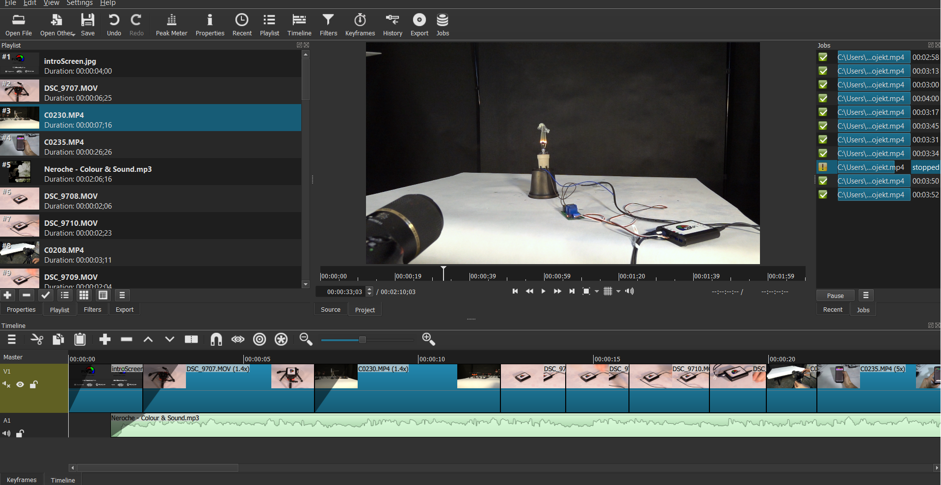
Montage video was done using Shotcut i'm not really experienced in video area as this was actually my second attempt ever, but this Software is really nice and i really enjoyed working with it.
![]()
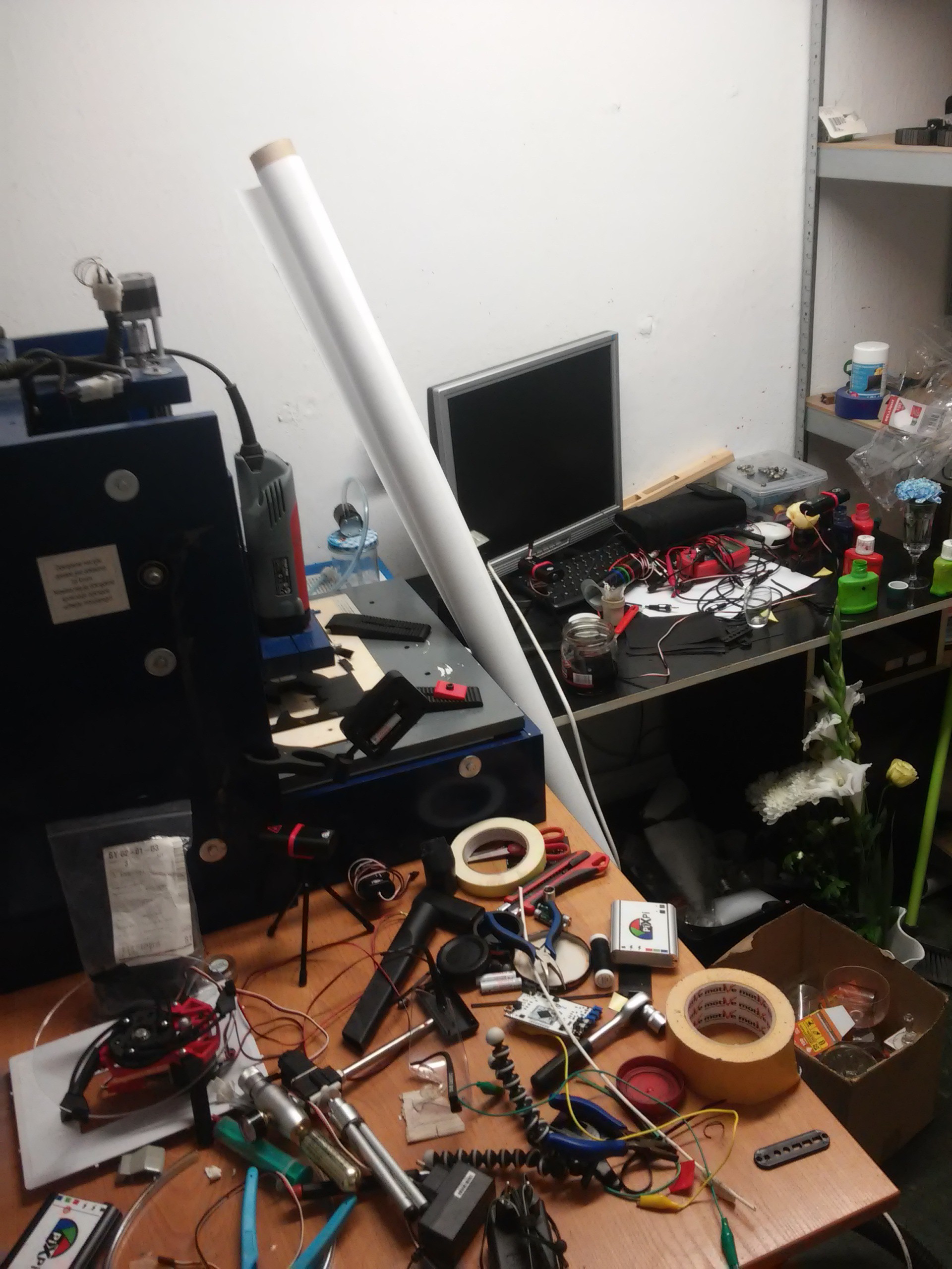
So now next challenge is to clean this mess which I created during this... ;O
![]()
In the heat of the work you don't think about cleaning.... and then you regret :) Thanks for reading, feedback is welcome :)
-
Additional/bonus module: Turntable
09/29/2019 at 14:49 • 0 commentsHello,
Last week was very busy as I was working hard on preparing submission video and I thought that I would like to have some shots for this clip using turntable and as I already got driving electronics which I used in macro rig I just needed to get some mechanical design. Thankfully I found very nice design on Thingverse:
https://www.thingiverse.com/thing:2031323
it's called StarScan and It has really really clever design, especially I liked it as it can be used with different sizes of table surfaces without replacing any part!
So i decided to give it a try I just needed to change was making legs longer as I needed to put controller under the motor, but it was quite easy, so below you can see quick demo:
![]()
So stay tuned and you will see this in action in project entry clip ;)
Modified files can be found in "files" part of this project page.
-
MacroSlider: let's take a first look
09/24/2019 at 20:18 • 2 commentsHello,
Today I want to share some work which I did in last days on motorised/macrorig module, let's take a quick look on some first effects:
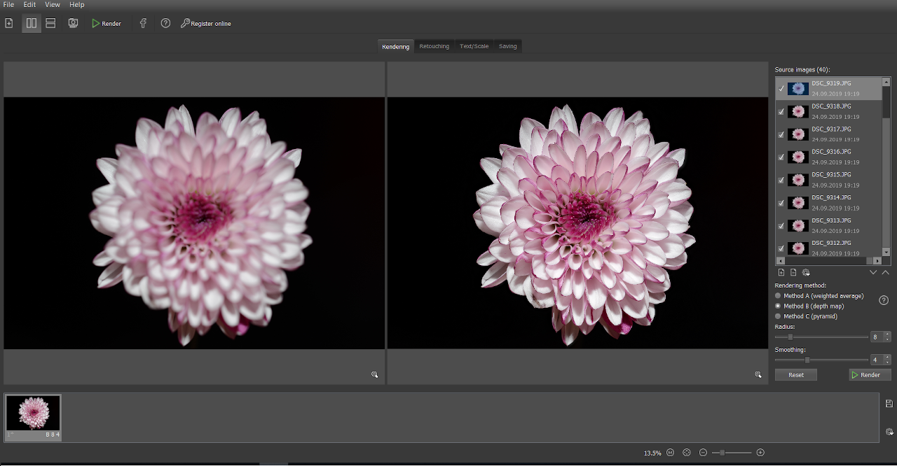
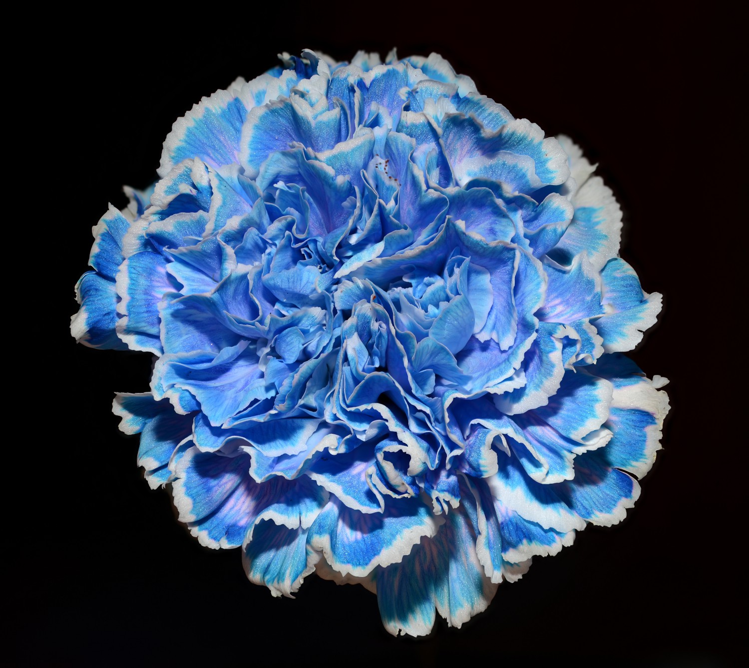
![]()
Above image was created by stacking 40 images stacked, each taken with 0,4mm step.
I found flowers to be quite simple for testing stacking technique.
Full resolution link![]()
All images used for stacking of above
So let's get back to technical aspects
Last time I decided that I should go on with Mechaduino servo driver I found it a good choice, as it can provide incredible precision and it's opensource, so I could modify software to work with signal generated by PiXPI.
Unfortunately i get one issue with Mechaduino, which's is that I could't get it fast and to progress until finals ends I came up with temporary solution, which was getting some Mechaduino clone which I found in local distribution in Poland(MKS Servo 42A), so first prototypes are based on it, but in future I plan to move on with Mechaduino as I find it has better and simpler software and also MKS servo has not onboard 5v voltage supply for logic, so i needed to add external step-down converter.
Anyway MKS-servo software which I modified to be controlled with PiXPi can be find here, additionally I changed function of onboard buttons to manual control(left-move back, right- move forward, center-disable/enable motor)
https://github.com/krzysztofkrzeslak/pixpi-stepper-driver/tree/master/MKS-SERVO42A![]()
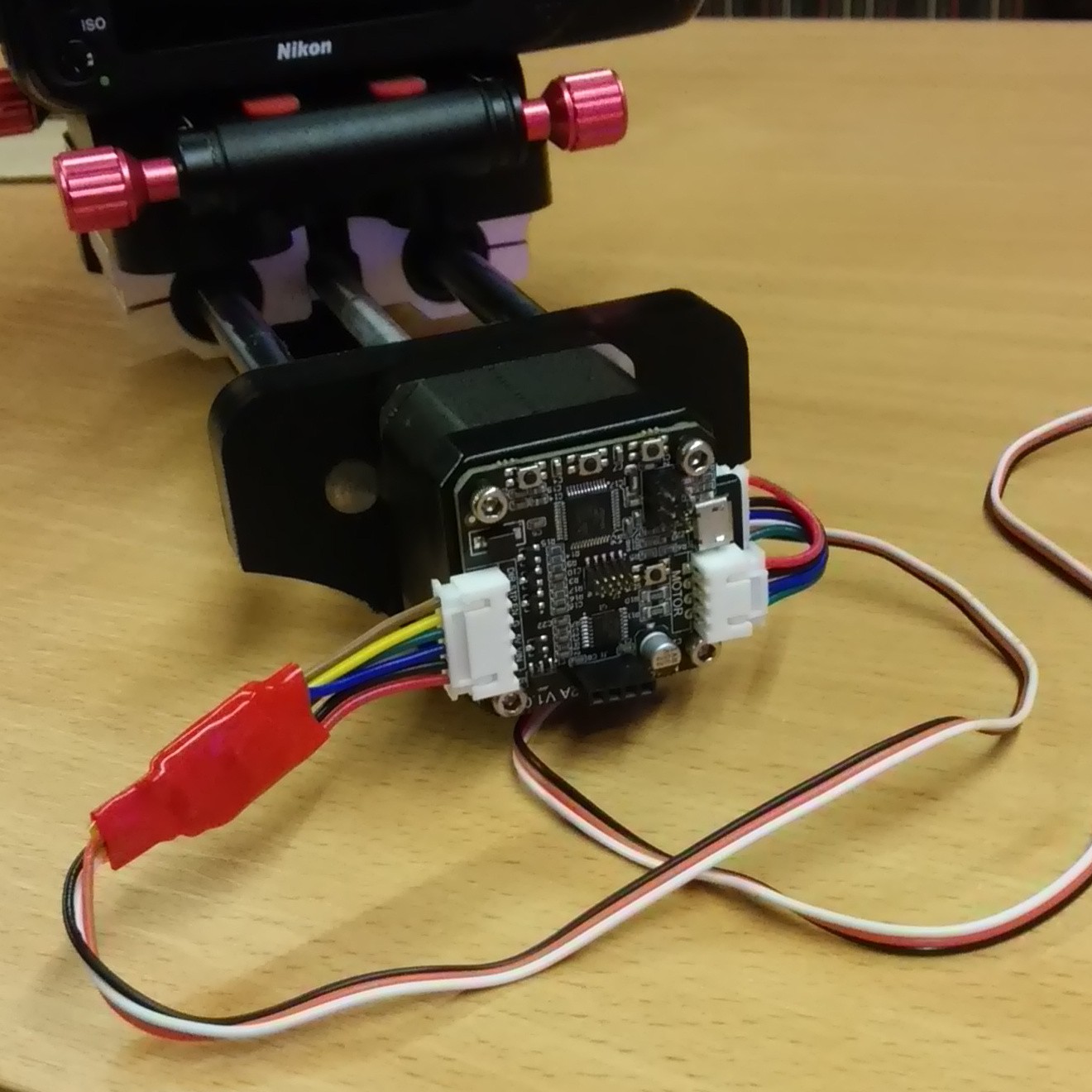
Macrorig with MKS servo as control board, on cable you can see stepdown converter for supplying logic(under red isolation) ![]()
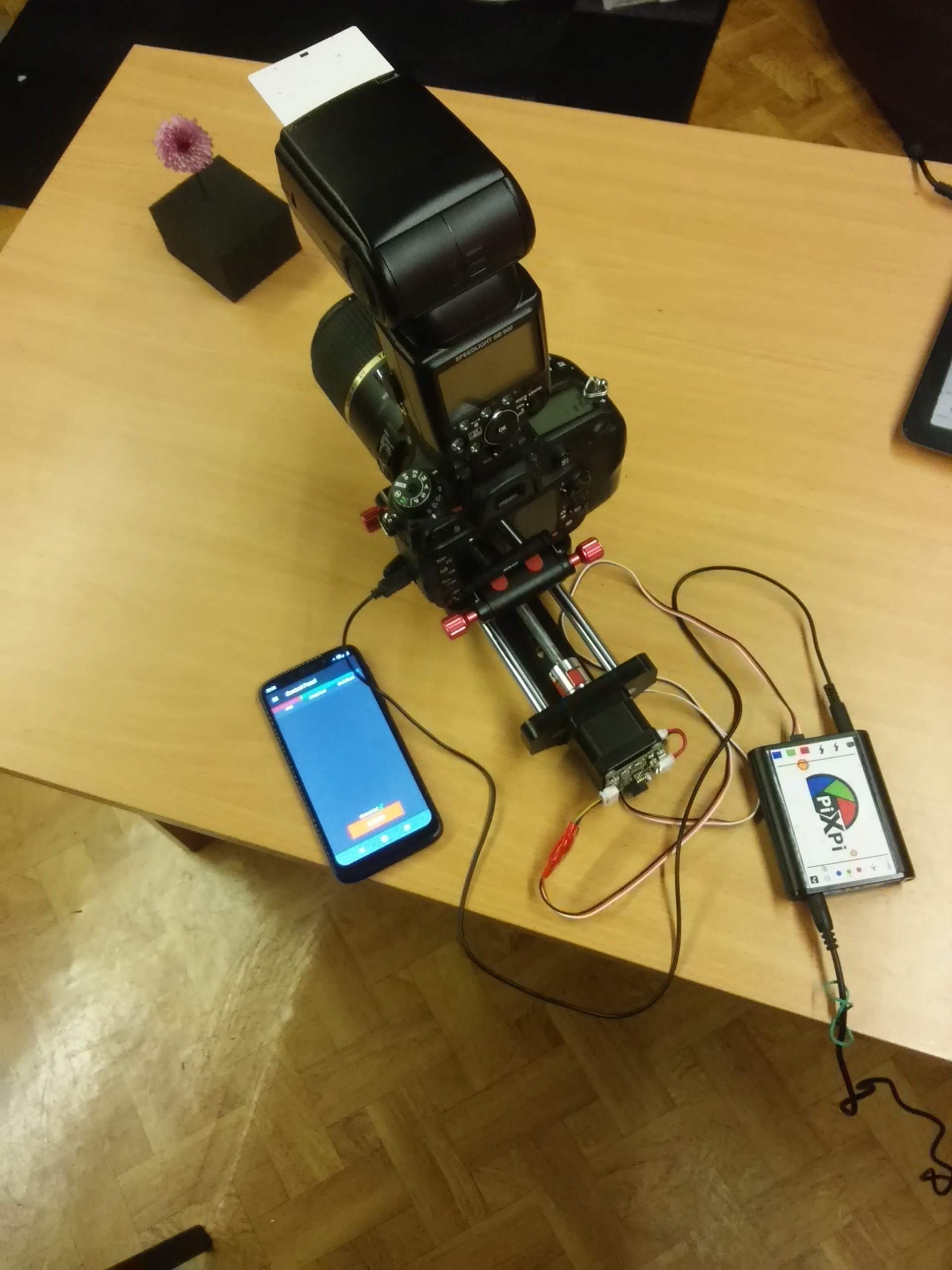
complete setup
Stacking software:
For stacking I used trial version of Helicon software, but after these test I can say that it's definitely worth buying full version, as initially I was afraid that learning of stacking software will take me some significant time, but this software has really simple user interface, you basically need just to open all images for stack and click one button ,it's fast and does it's job great, additionally you can export stacking animation from it, so I found 55 dollar license(for pro version/year) quite reasonable.![]()
Some more example:![]()
50 images stacked, step 0,5mm
Full resolution link![]()
50 images stack, step 0.4mm
Full resolution link![]()
Images used for stacking -
Power driving mode
09/12/2019 at 18:50 • 0 commentsHello,
Today I want to introduce new feature it's called: "Power driving mode", it's mode for driving some "action" modules which can be handy in some situations as it's purpose is to drive some modules without any additional external circuit.
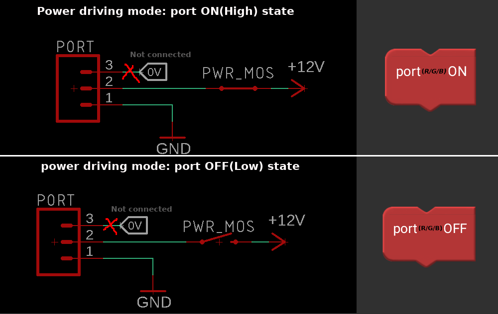
But let's start from recalling how "action" modules are driven in "normal" mode, let's see below image:
![]()
Port circuit behavior in "normal" mode In "normal mode" power Mos-Fet of port is open all the time, low current signal for driving module is delivered through "com" pin.
And how it looks in Power driving mode:
![]()
In power driving mode "com" pin is not used, instead just supply pins are controlled
In power driving mode "com" is not used(should not be connected) and driving of module can be done through on-board power transistor, so for example you can connect solenoid, or anything other, theoretically max current is approx. 5A(60W), but till this moment I tested max 3A in pulse.
how to enable:
I modified App "port configuration" screen to handle enabling of this mode, after choosing port function mode, checkbox where you can select it will appear:
![]()
Power drive mode is valid only for "output" port mode Below you can find small demo with driving some random peripherals:
Advantage of using this mode:
You can drive simple "action" modules without external circuit, so for example till this moment I was using board small with Mos-Fet to open and close valve(solenoid) in response to state on "com" pin, but with power driving mode solenoid can be connected directly to "gnd" and "+12v" pins of port and driven just with toggling supply on this pins.
Disadvantage of this mode:
When you first think about it using such driving mode should be "best" way of handling such use case as driving solenoids, valves, etc. So maybe you can think, why even I bothered to create "normal" mode as first?
there's one valid reason for it, when you will take a look at solenoid driving board you can see button there which is used to "emergency/maintenance" opening of valve and I found it really handy to have such button, especially when I was experimenting with "liquid gun" module which was valve with syringe pressurized by springs and I needed way to fill this and it was really hard to do this when I had to control valve open/close from app.
It's a little bit easier with "droplet module", but still it's handy to have possibility to emergency valve open for example for filling chamber of valve or just emptying it after use. Without supplying module all the time, there will be no possibility to open valve without using app.
so in some(or most) cases it's handy to had module supplied all the time.
-
Finals! Wow and what are my further plans
09/11/2019 at 16:32 • 0 commentsHello,
PiXPi is in finals of 2019 Hackaday Prize!
There was so much great projects submitted and I really feel honoured to be among those 20 chosen for final round.
Also I found it awesome to see my project described in finalists announcement post, thanks Mike for nice words! I really want to appreciate this so I thought the best way to say thanks will be to put as much heart into this project as possible, "heart" in this case, can be translated into "hard work" ;)
What now:
I just cooled down a bit to be able to think consciously about that what need to be done as there is not much time, so I came to conclusions that I need to prioritise some areas where the biggest improvements can done, so according to this I chosen as main focus :
1. Introduce new feature which is "power driving mode" of modules ports:
I was working on it lately, so stay tuned, it's almost ready and will be soon described in project log.
2. Finish and show effect of usage "motorised/stepper" module:
Currently I got some base which I show in previous logs, but I was not happy with stepper motor driving electronics and during seeking for better solution I came across project called: "Mechaduino"... which by the way was 2016 Hackaday prize entry!!: https://hackaday.io/project/11224-mechaduino and I realised that it should be possible to communicate with my controller as Mechaduino is opensource, so possibly it can be quite easy to modify software of Mechaduino to be controlled through PiXPi controller.... Isn't opensource great?! :)
3. Work hard on new video:
Last, but very important point, as ti's one of requirements of final entry is to create 2-5 minute video which will show project and I got already some initial idea how to do this, but I know it will be quite challenging to do it right.
Optional point: New hardware design with better ports protections, after experimenting with "power driving mode" I came to conclusions that I will feel safer when power driving transistors gates for each port will be driven through optoisolators, but it's more on good practice rather that new feature introduction as i experimented quite heavily with power driving and I was not able to burn VoCore port with current protections. Possibly I will start to work on it after 1-st of October.
What you think about it?! :)
It would be really nice to hear some thoughts of community on this project, as this was my main motivation to publish this project here, so don't hesitate to share some I will really appreciate to hear some(Even those critical ones).
-
Controller board specification and software sources
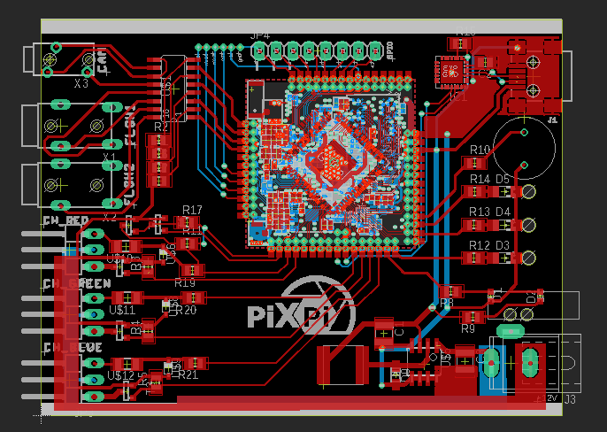
08/24/2019 at 18:09 • 0 commentsHello today I wanted share quick summary specification of current controller board design,
and as this project is meant to be opensource I want to share some sources today I Think both will be good summary for entry round of this contest :).
![]()
v0.9(current)controller version Controller software:
https://github.com/krzysztofkrzeslak/pixpi-controller-app
it's Python app sources which is running on controller.
Hardware specification:
1 x Optoisolated camera port(2,5mm jack) for camera focus/wake and trigger
2 x Optoisolated Flash port(3,5mm jack) for flash triggering
3 x module port, which can be used in following modes:
Port Red: Input, Output, Com(1-wire), Pulse
Port Green: Input, Output, Pulse
Port Blue: Input, Output, Pulse
Each port has 3 pins: Signal, 12V, Gnd
Ports connector fits standard servo connectors
8 x Gpio pins
1 x mini-B usb connector for accessing Linux command line/serial console.
1 x 1,27mm 6pin SPI connection for complete flash writing(unbricking, bootloader change, etc. )
1 x DC jack for 12v supply (should be tolerant up to 22v)
2 x status led: supply, ready
3 x port status led
1 x Buzzer for state indication
Powered with opensource VoCore2 system on module (https://vocore.io)
Which provides:
- Mediatek MT7628, 580 MHz SoC
- Memory(ram): 128MB, DDR2
- Flash: 16MB
- Running under Linux(OpenWrt) control.
It's also fully OpenSource: Complete specifications and sources available on: https://vocore.io/v2.html
-
Some new photos
08/24/2019 at 14:02 • 2 commentsHello,
This time I wanted to share some photos which I took lately, within this I also want to show how setup and program look like for each shoot and also you will see example how modules can be combined.
Doing photos like below was really simple using relay module
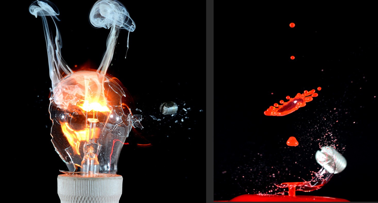
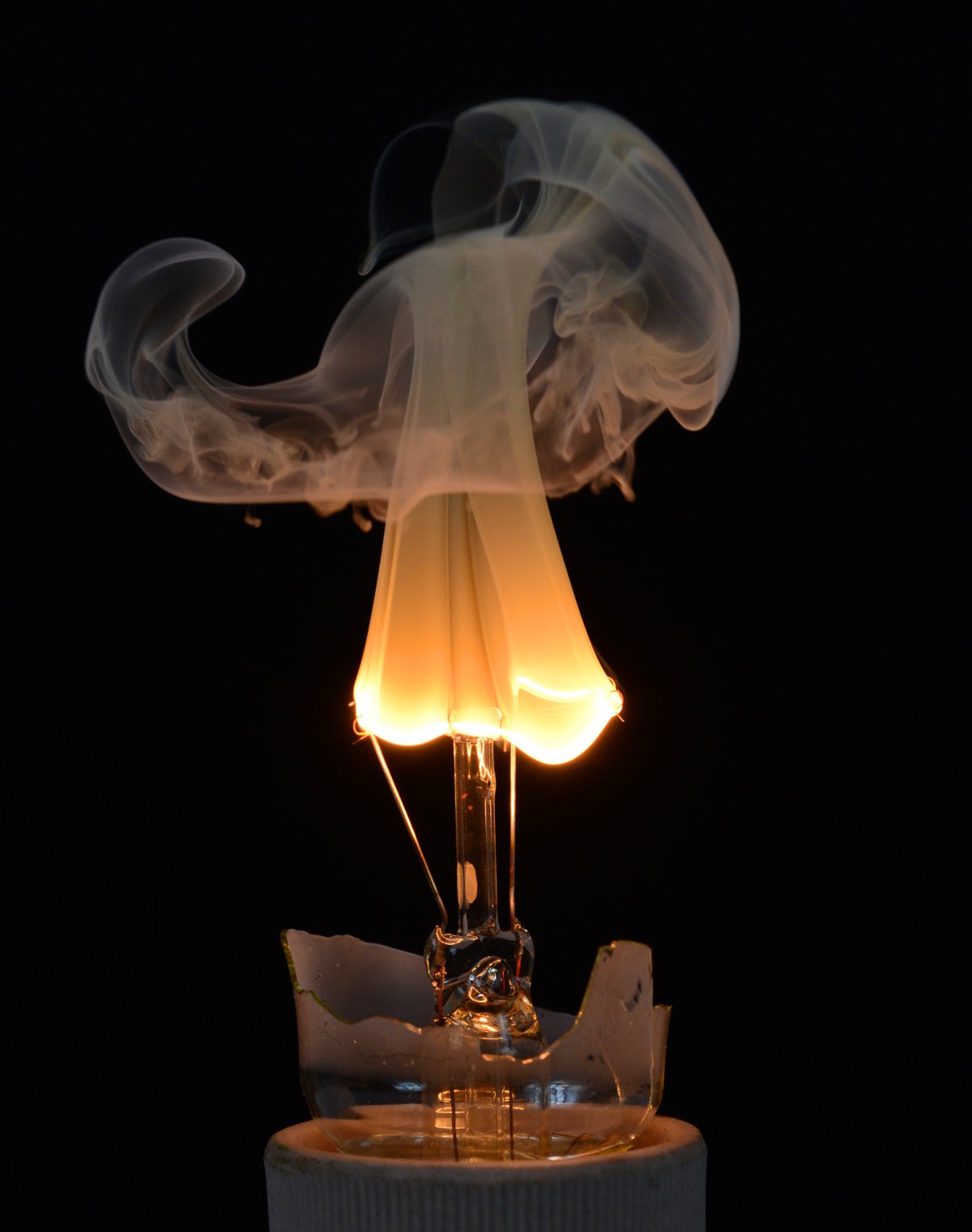
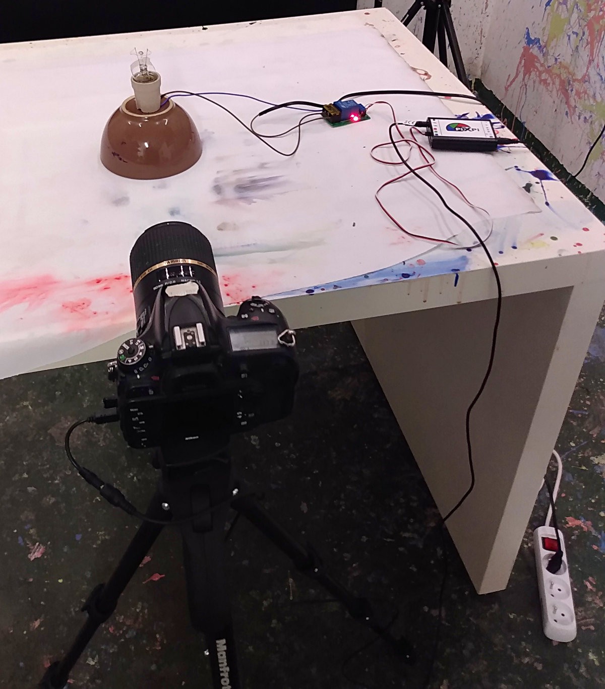
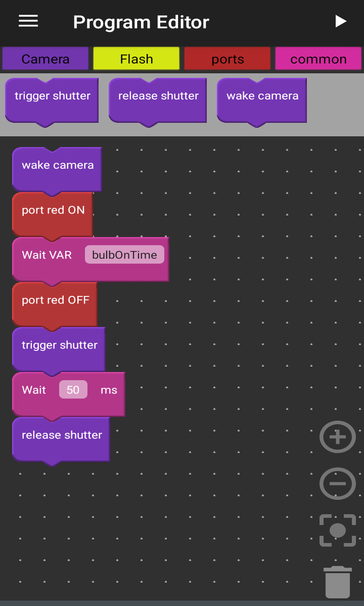
Burning bulb filament ---------- more ----------Crashed bulb was hooked to mains AC, so needed to be extra careful here I used power strip with a switch, so every time I was getting close to it i just switched it off. So safety was biggest challenge here, other thing was easy, program was done in that way that it just turned on relay for short time and then camera was triggered, usually bulb was turned on for 100-200ms,but I used block which enabled me to change delay from control panel, so for each shoot I could change it.
![]()
Behind the scene ![]()
Used program
Some more from this session:
Hmm so maybe let's try to shoot with bullet to it?
I also got some partially crashed bulbs with non broken filaments, so I thought maybe It will be good idea to, try to combine this and shoot with projectile to it while it filament was burning and this idea was not so good, as light from bulb was causing some motion blur, but I got one quite decent photo, which you can see above.
![]()
Setup ![]()
Used program Some more from this session:
Shooting to colliding droplets with projectile
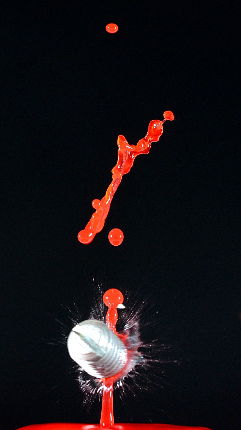
Some final effect I was also done some photos of colliding droplets hit with projectile from pneumatic gun and generally it was not so hard as I thought, surprisingly what made the most difficulty this day was to make droplets colliding nicely, possibly this was due liquids properties which i used or shape dish or something, hard to say, but droplets was not so tall and nice, but anyway i was able to catch some photo which can be shown as example.
![]()
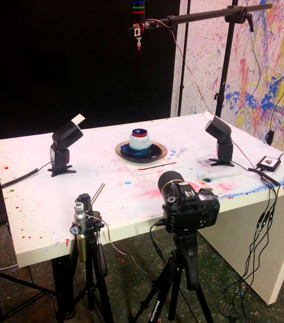
Setup which was used 2 flashes connected to one port(through dividing cable), droplet module(port red) and pneumatic gun(port green)
![]()
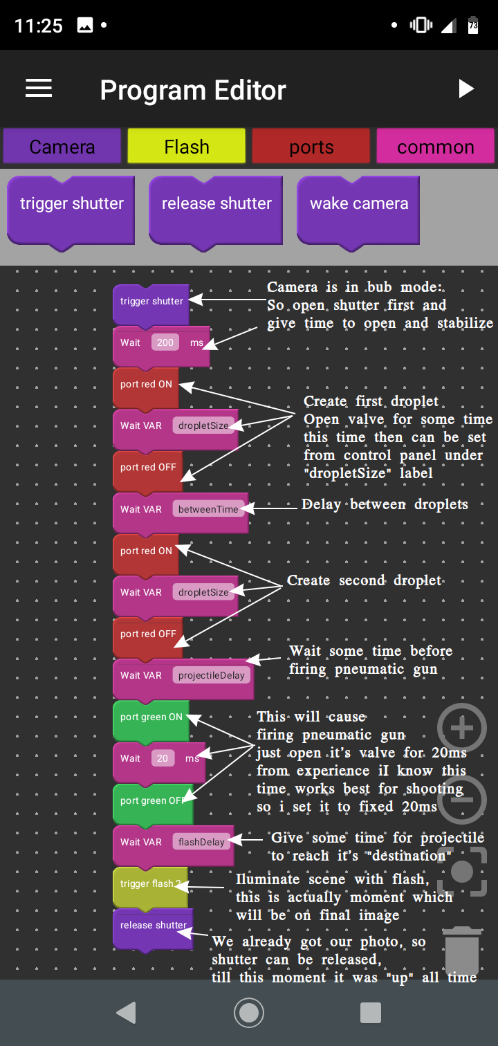
Program within which I made presented photo, with small explanations added ![]()
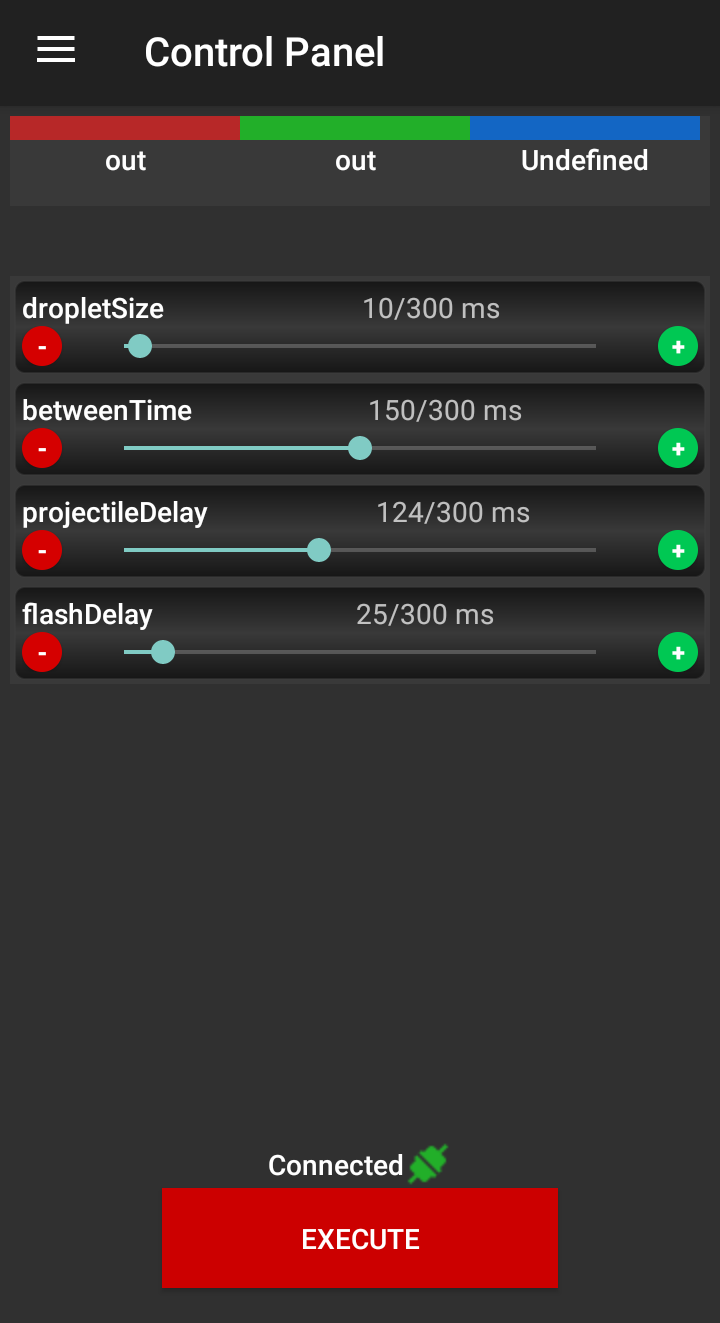
This how control panel looked like for above program, when you use "wait VAR" block, you will get slider to adjust this delay in control panel under label set in program editor.
And one more from session:
Update 8.09.2019:
I made some few more tries with catching photo of colliding droplets which are hit by projectile, setup was almost same as above(only container which hold liquid where drop is hitting was different, as I observed that it can make significant difference in first droplet "jump" height):
-
Macrorig controlled from app
08/20/2019 at 19:41 • 0 commentsHello
As i wrote in previous update lately I was working on adding possibility to control macrorig/stepper driver from android app, and just wanted to share some effects of it:
Generally it works, it's simple and there are some fine tweaks still needed, but it will come in future, what was currently added on app side is:
Added "step" mode in ports configuration screen:
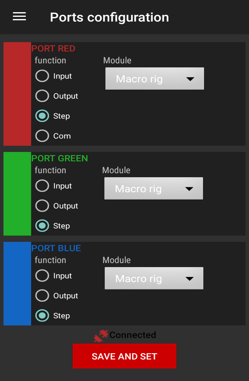
![]()
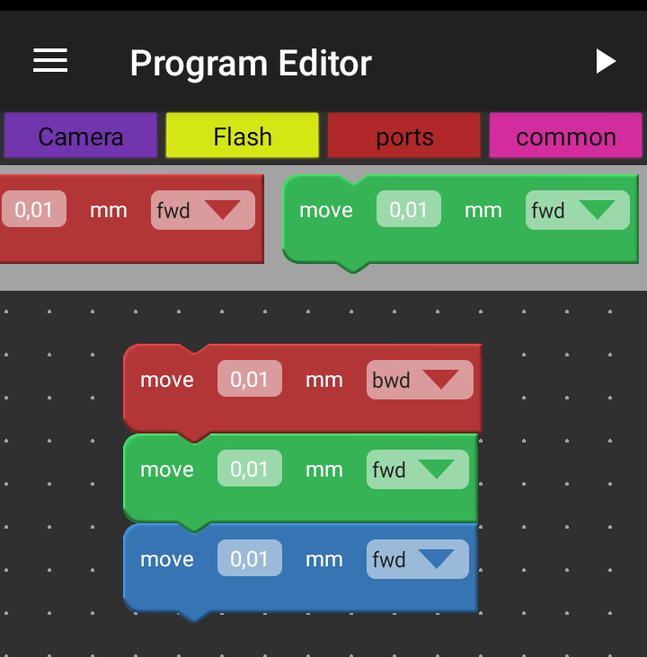
"Step" mode can be set on each port After setting port into "step" mode following block will become available:
![]()
With these block you can move steppers forward and backward and set desired travel, currently smallest possible move for macrorig is 0,005mm(1 step). -
it's alive! stepper driver with macro-slider
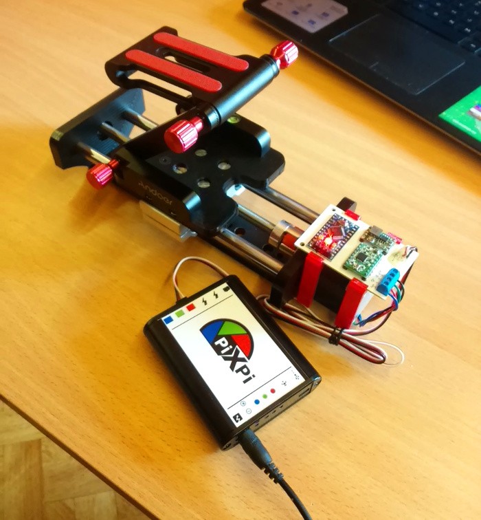
08/18/2019 at 15:13 • 0 commentsHello, today I was finally able to make macro-slider, so I wanted to show off a bit, below is a small demo:
Currently utilizing of this feature needs to be imlemented on Android app side, but for controller testing i just sent http request from laptop, so next step we be adding blocks for driving this from Android app.
![]()
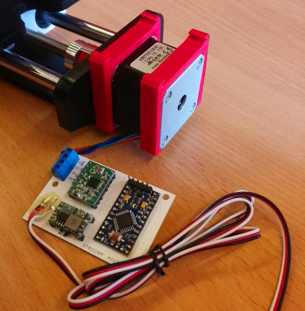
I also designed and 3-d printed some holders for driver board ![]()
As i mentioned in one of logs i decided to use "pulse" like interface for driving stepper boards, it's really simple and work like that:
pulses below 2ms time will make stepper move in one direction
pulses above 2ms will make it's moving in opposite direction
and till now it works pretty well.
As currently i've used 1mm/rev trapezoidal screw and stepper motor has standard 200steps per revolution so theoretically it should have 5-microns resolution.
Currently i already had some ideas about new driver board as I think it will be handy to have there some buttons to "manually" move slider.
So watch for updates... :)
-
New black robe and few words about cases
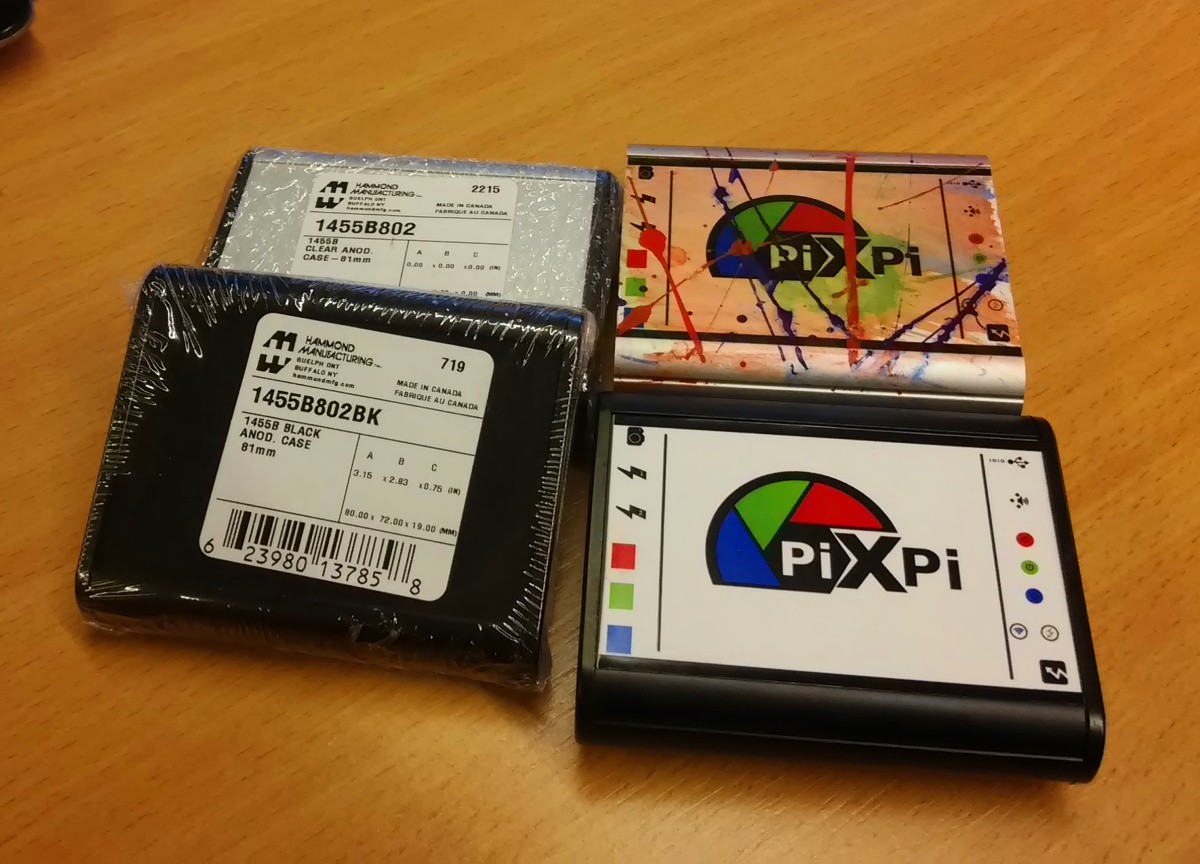
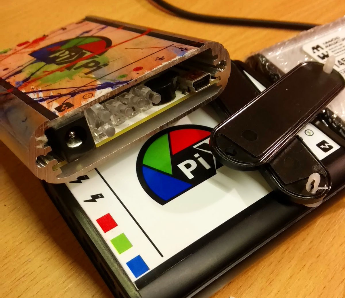
08/17/2019 at 19:01 • 0 commentsController in anodised black casing Hello, Today I wanted share photo of controller in "a new robe" which is anodised black case I bought those black cases some time ago, but not really used till this time, now as previous case got little dirty I thought that maybe it's a good moment to test this variant.
By the way I also realised that in log about board design i skipped somehow case selection topic, it necessarily should be there as case selection was one of first thing which I did when started this project, so board dimensions was designed to fit this cases(to be precise first prototype was intended for 100mm version[1455b1002], but after moving to esp then to vocore I switched to smaller 80mm version[1455b1002] ).
![]()
I really like this cases as they look very nice and are surprisingly cheap(less than 10 dolars),
they're manufactured by Hammond manufacturing.![]()
After removing front panel board can be slidden in/out, as it's held by those ribs on sides generally I can't make my decision which color version I like more, this one or old one(natural aluminium), so some opinions are appreciated :)
 krzysztof krzeslak