Op-Amp Explorer:
- 2 Channels
- One inverting channel
- One Non-Inverting Channel
- Utilizes very low cost LM741
- AC or DC Coupling Selection
- Adjustable Gain through R5 and R6 (Using variable resistors)
Already have an account? Log in.
To make the experience fit your profile, pick a username and tell us what interests you.
Op-Amp Explorer:
Explorer1.pdfPreview of theory section in kit manual.Adobe Portable Document Format - 391.08 kB - 08/08/2019 at 04:35 |
|
|
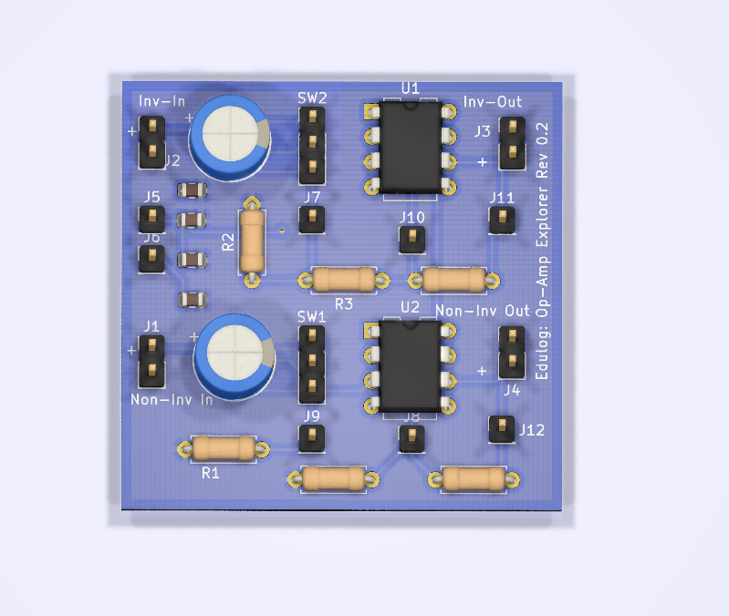
Hey everyone, I finally had some time to work on projects again, and reworked the Op-Amp explorer board. I changed the general layout to make it more intuitive for a beginner, the components are laid out on the board in representative locations from the schematic. There are now also test points, thanks to a suggestion made to me. This should allow for quick measurements from points in the circuit that were not accessible in the previous revision.
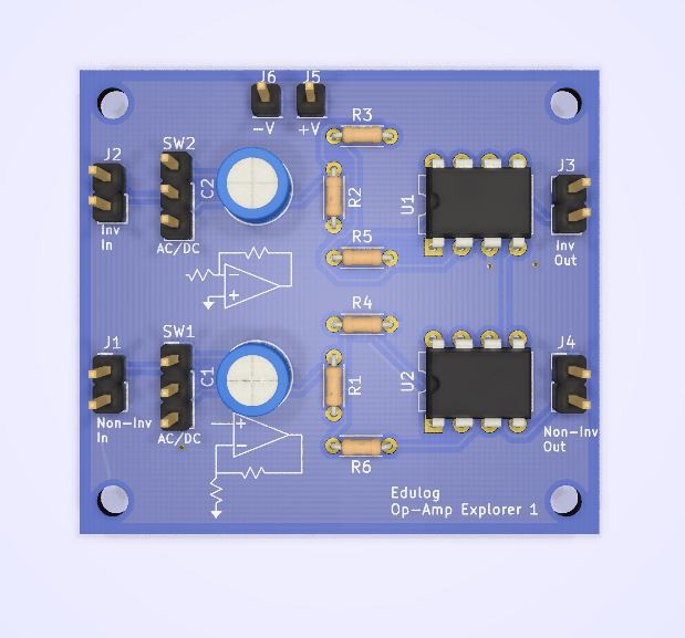
Hey everyone,
I have just completed the preliminary design for the Op-Amp Explorer 1, which will be referred to as OE-1. This is a board with one inverting channel, and one non-inverting channel. The most glaring change that needs to be made is to add the potentiometers to the layout, which are currently represented as resistors. I was hoping to find some small-format rheostats in place of the pots, but the potentiometers appear to be less expensive. Currently, the module is to be presented as a kit for assembly by the user. The only pre-assembled part are the SMD power decoupling capacitors on the back.
I am starting work on the power supply board, which should be done shortly. It uses a voltage divider, with a virtual ground with 7805 (+) and 7905 (-) regulators to give a +/- 5V output. This could be stepped up in the future with a beefier wall-wart, or ultimately, a boost regulator.
Please stay tuned for updates, and feel free to offer any input on the project that you may have.
Thank you! I just added some test points to the board and did some other rework based on your suggestion.
I'm glad you liked the idea. Best of luck with the project.
 I do plan on ordering boards, and constructing this revision soon. Then, I will work on writing an assembly guide, and update the workbook. As always, feel free to contact me more suggestions and comments.
 SimonXi
 Chris Hamilton
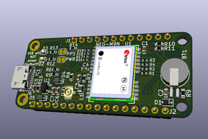
 sirmylesavery
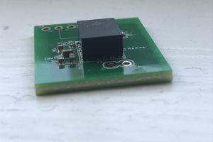
Hay man i wanted to say that this is an amazing idea and i hope you help beginners learn.
May i make a suggestion? I'm an electronics engineer and i currently work as a PCB designer. One of the things i like to do on prototypes (if i have the space for it) is to use a header as a "test point" for interesting signals. It may be a good idea to have something like that, so beginners can measure signals easier. Just as an example - test points directly on the inputs of the op amp.
Hope i was not too long winded with the suggestion?. Best of luck with your projects :)