davedarko
-
I2C on an Attiny85
01/01/2017 at 21:47 • 0 commentsSo I thought I would just add the Attiny85 family to the boards by adding the following link to my Additional Boards Manager URLs in my Arduino 1.6.9 IDE and get away with it and use the wire library to hack a little LED PWM backlight controller together. But since that didn't work for the tone() lib on the #Nyan Board , why would it here?
https://raw.githubusercontent.com/damellis/attiny/ide-1.6.x-boards-manager/package_damellis_attiny_index.json
So I then look around and find this library on GitHub https://github.com/rambo/TinyWire and with it's help I was able to whip together the LED controller! The idea here is that the pin 3 is connected to the PI and when toggled will write the PWM to pin 4. This PWM value can be set via I2C address 0x04.
#define I2C_SLAVE_ADDRESS 0x4 #include <TinyWireS.h> int pwm_value = 127; #ifndef TWI_RX_BUFFER_SIZE #define TWI_RX_BUFFER_SIZE ( 16 ) #endif void setup() { TinyWireS.begin(I2C_SLAVE_ADDRESS); TinyWireS.onReceive(receiveEvent); pinMode(3, INPUT); pinMode(4, OUTPUT); } void loop() { TinyWireS_stop_check(); writeLed(); } void writeLed() { if (digitalRead(3) == HIGH) { analogWrite(4, pwm_value); } else { digitalWrite(4, LOW); } } void receiveEvent(uint8_t howMany) { if (howMany < 1) { // Sanity-check return; } if (howMany > TWI_RX_BUFFER_SIZE) { // Also insane number return; } // ignore write address TinyWireS.receive(); howMany--; if (!howMany) { // This write was only to set the buffer for next read return; } while(howMany--) { pwm_value = TinyWireS.receive(); } } -
changing pins works!
11/27/2016 at 21:06 • 1 commentI've mapped pin12 and pin13 to play audio! woot.
The following code is not mine and taken from:
https://www.raspberrypi.org/forums/viewtopic.php?f=44&t=39138
I just want to have everything in one place and have a copy of it somewhere.
/*
Utility to switch Raspberry-Pi GPIO pin functions
Tim Giles 01/04/2013

Usage:
$ gpio_alt -p PIN_NUMBER -f ALT_NUMBER

Based on RPi code from Dom and Gert, 15-Feb-2013,
and Gnu getopt() example
*/

#include <ctype.h>
#include <stdio.h>
#include <stdlib.h>
#include <unistd.h>
#include <fcntl.h>
#include <sys/mman.h>

#define BCM2708_PERI_BASE        0x20000000
#define GPIO_BASE                (BCM2708_PERI_BASE + 0x200000) /* GPIO controller */
#define PAGE_SIZE (4*1024)
#define BLOCK_SIZE (4*1024)

int  mem_fd;
void *gpio_map;
volatile unsigned *gpio;
void setup_io();

// GPIO setup macros. Always use INP_GPIO(x) before using OUT_GPIO(x) or SET_GPIO_ALT(x,y)
#define INP_GPIO(g) *(gpio+((g)/10)) &= ~(7<<(((g)%10)*3))
#define OUT_GPIO(g) *(gpio+((g)/10)) |=  (1<<(((g)%10)*3))
#define SET_GPIO_ALT(g,a) *(gpio+(((g)/10))) |= (((a)<=3?(a)+4:(a)==4?3:2)<<(((g)%10)*3))

#define GPIO_SET *(gpio+7)  // sets   bits which are 1 ignores bits which are 0
#define GPIO_CLR *(gpio+10) // clears bits which are 1 ignores bits which are 0


int main (int argc, char **argv) {
  int opt, flag, n_pin, n_alt;
  flag=0;

  while ((opt = getopt (argc, argv, "hp:f:")) != -1) {
    switch (opt) {
    case 'h':
      break;
    case 'p':
      n_pin = atoi(optarg); flag |= 0b0001; break;
    case 'f':
      n_alt = atoi(optarg); flag |= 0b0010; break;
    case '?':
      // getopt() prints error messages, so don't need to repeat them here
      return 1;
    default:
      abort ();
    }
  }

  if (flag != 0b0011) {
    fprintf (stderr, "Usage:\n$ gpio_alt -p PIN_NUM -f FUNC_NUM\n");
    return 1;
  }

  setup_io(); // Set up gpi pointer for direct register access
  INP_GPIO(n_pin);  // Always use INP_GPIO(x) before using SET_GPIO_ALT(x,y)
  SET_GPIO_ALT(n_pin, n_alt);

  printf("Set pin %i to alternative-function %i\n", n_pin, n_alt);

  return 0;
}


void setup_io() {
   /* open /dev/mem */
   if ((mem_fd = open("/dev/mem", O_RDWR|O_SYNC) ) < 0) {
      printf("can't open /dev/mem \n");
      exit(-1);
   }

   /* mmap GPIO */
   gpio_map = mmap(
      NULL,             //Any adddress in our space will do
      BLOCK_SIZE,       //Map length
      PROT_READ|PROT_WRITE,// Enable reading & writting to mapped memory
      MAP_SHARED,       //Shared with other processes
      mem_fd,           //File to map
      GPIO_BASE         //Offset to GPIO peripheral
   );

   close(mem_fd); //No need to keep mem_fd open after mmap

   if (gpio_map == MAP_FAILED) {
      printf("mmap error %d\n", (int)gpio_map);//errno also set!
      exit(-1);
   }

   // Always use volatile pointer!
   gpio = (volatile unsigned *)gpio_map;
}
One time setup:
gcc -o gpio_alt gpio_alt.c
sudo chown root:root gpio_alt
sudo chmod u+s gpio_alt
sudo mv gpio_alt /usr/local/bin/
Cron that:
gpio_alt -p 13 -f 0 gpio_alt -p 12 -f 0 -
boards ordered
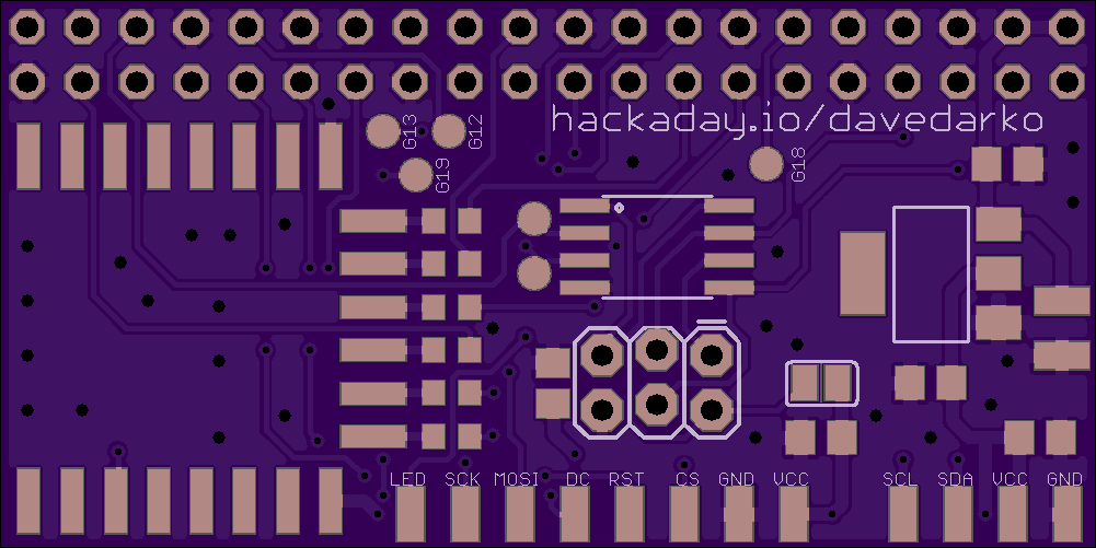
11/24/2016 at 16:04 • 2 commentsThere is currently no sound on this board, but I've ordered this anyway with some testpoints for the possible sound pins and an extra board you can check out below (not designed by me but someone who builds raspberry pi portables). The attiny85 is connected to the PI via I2C and the TFT LED output of the driver - think basic on/off via driver and pwm via i2c. It's a decent prototyping board to get along, I think.
![]()
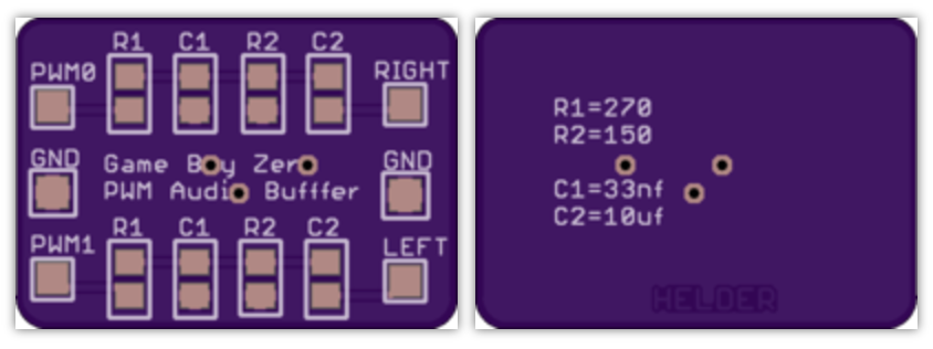
Gameboy Zero PWM Audio SMD - by Helder
https://oshpark.com/shared_projects/qUEOjE0n
![]()
-
party on!
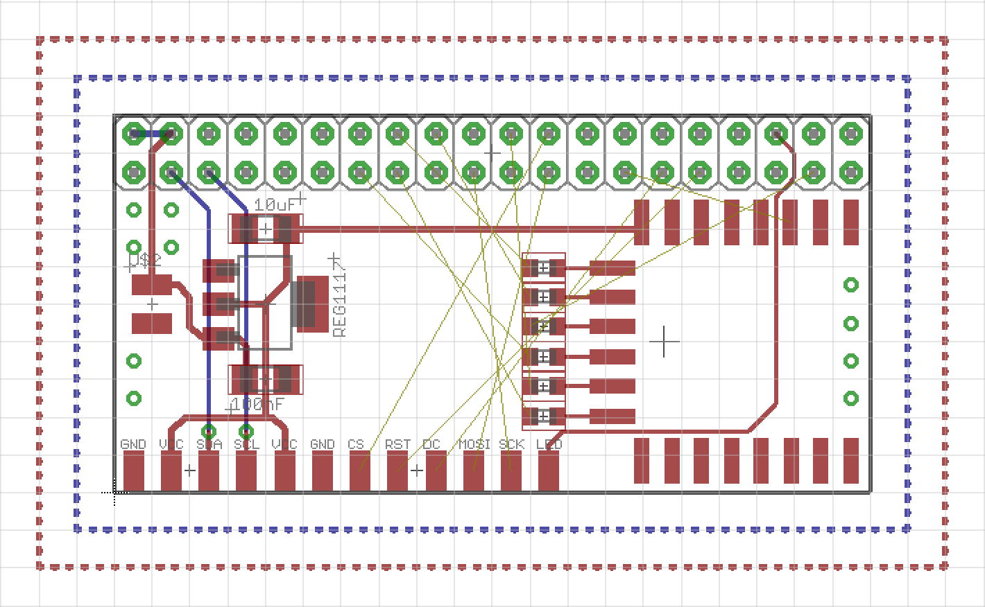
11/19/2016 at 20:53 • 3 commentssoo, still not validated, but I'm happy to give it a try as soon as possible - a breakout board to connect the Raspberry PI with the TFT display, wi-fi and I2C and stuff. I'm tired.
![]()
-
eyes for dem pis!
11/18/2016 at 08:52 • 0 commentsYay, I won something! When I saw the blog post about the Enlightened Raspberry Pi Contest I must have over looked that I won something, because I was surprised when Adam Fabio wrote me to get my address to send me a sweet camera module! Not sure if it will end up in this project or the cluster thing, but I will find a good project for it! With all those PIs I have it shouldn't be a problem.
https://hackaday.io/contest/15532/log/49182-and-the-winners-are -
more wiring adventures
11/10/2016 at 23:13 • 2 commentshttps://docs.google.com/spreadsheets/d/1G__6bgoXlyRspCsvcebNKyEUlDYK1BtcHlGwnXLq2EA/edit?usp=sharing
https://hackaday.io/project/8678/instructions
http://marcosgildavid.blogspot.de/2014/02/getting-ili9341-spi-screen-working-on.html
https://learn.adafruit.com/introducing-the-raspberry-pi-zero/audio-outputs
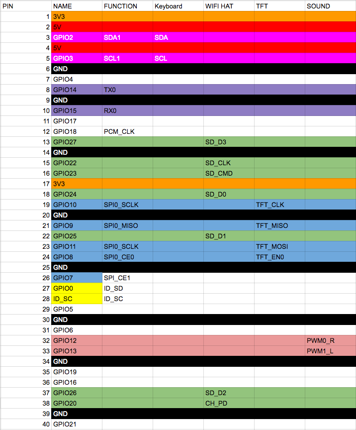
All that Pin X is GPIO Y got me confused... so I had to "map" the pins.
![]()
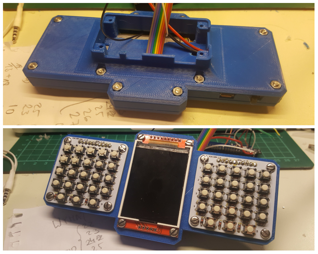
Nothing but the keyboard works yet.
Here's the closed case.
![]()
-
Odyssey continues
11/09/2016 at 20:55 • 1 commentPython script is about the same where I was before. Python is weird when you're coming from JS and PHP, let me tell you.
AND the uinput part works!! woot! Thanks to adafruit, mainly. And my copy and paste skills.
I still need to map the keys and find the driver for the display (MacGyver was drawn by an adafruit python library).
import subprocess import sys import time import Adafruit_GPIO as GPIO import Adafruit_GPIO.I2C as I2C import Adafruit_GPIO.PCF8574 as PCF import uinput row = 1 rowI = 1 col = 1024 addressH = 0x20 addressL = 0x21 gpioH = PCF.PCF8574(addressH, busnum=1) gpioL = PCF.PCF8574(addressL, busnum=1) KEY_MAPPING = { 0: uinput.KEY_UP, # Each line here should define a $ 1: uinput.KEY_DOWN, # that maps the capacitive touch $ 2: uinput.KEY_LEFT, # to an appropriate key press. 3: uinput.KEY_RIGHT, # 4: uinput.KEY_B, # For reference the list of possi$ 5: uinput.KEY_A, # values you can specify is defin$ 6: uinput.KEY_ENTER, # http://www.cs.fsu.edu/~baker/de$ 7: uinput.KEY_SPACE, # http/source/linux/include/linux$ } # Make sure uinput kernel module is loaded. subprocess.check_call(['modprobe', 'uinput']) # Configure virtual keyboard. device = uinput.Device(KEY_MAPPING.values()) def shiftRange (start, end): while start > end: yield start start = start>>1 while True: rowS = 0x03FF ^ row rowL = (rowS<<5) & 0x00FF rowH = (rowS>>3) & 0x00FF addL = rowL | 0x1F addH = rowH gpioH.iodir = addH gpioL.iodir = addL gpioH._write_pins() gpioL._write_pins() keys = gpioL._read_pins() keys = keys & 0x1F; keysI = 1 for k in shiftRange(16,0): if k & keys == 0: device.emit_click(KEY_MAPPING[rowI-1]) time.sleep(0.5) keysI += 1 rowI += 1 row = row << 1 if row == col: row = 1 rowI = 1 -
Keyboard adventures - Episode 2
11/06/2016 at 00:53 • 0 commentsThat's my current state for the actual keyboard. I will probably drop this and move over to python, since I just don't get the uinput stuff in C and the linux input system. Hey future Dave, research before developing, you know this stuff!
https://github.com/adafruit/Adafruit_Python_MPR121
#include <wiringPi.h> #include <wiringPiI2C.h> #include <stdio.h> int fdH; int fdL; int fd; int rpl; int ret; int row = 1; int rowI = 1; int col = 1024; int i = 0; int j = 0; int k = 0; void printByte(int a) { printf("\n0x"); for (j=0x8000; j>0; j=j>>1) { if ((a&j) > 0) printf("1"); else printf("0"); } } int main (void) { wiringPiSetup (); fdH = wiringPiI2CSetup(0x20); // rows only fdL = wiringPiI2CSetup(0x21); // cols with rows for (;;) { int rowS = 0x03FF ^ row; int rowL = (rowS<<5) & 0x00FF; // High int rowH = (rowS>>3) & 0x00FF; // Low int addL = rowL | 0x1F; int addH = rowH; wiringPiI2CWrite(fdH, addH); wiringPiI2CWrite(fdL, addL); int keys = wiringPiI2CRead(fdL); keys = keys & 0x1F; int keyI = 1; for (k=0x10; k>0; k=k>>1) { if (!(k & keys)) { delay(50); printf("%i\t%i\n", keyI, rowI); } keyI++; } rowI++; row = row << 1; if (row == col) { row = 1; rowI = 1; } } return 0 ; } -
I2C wiringPI for the PCF8574
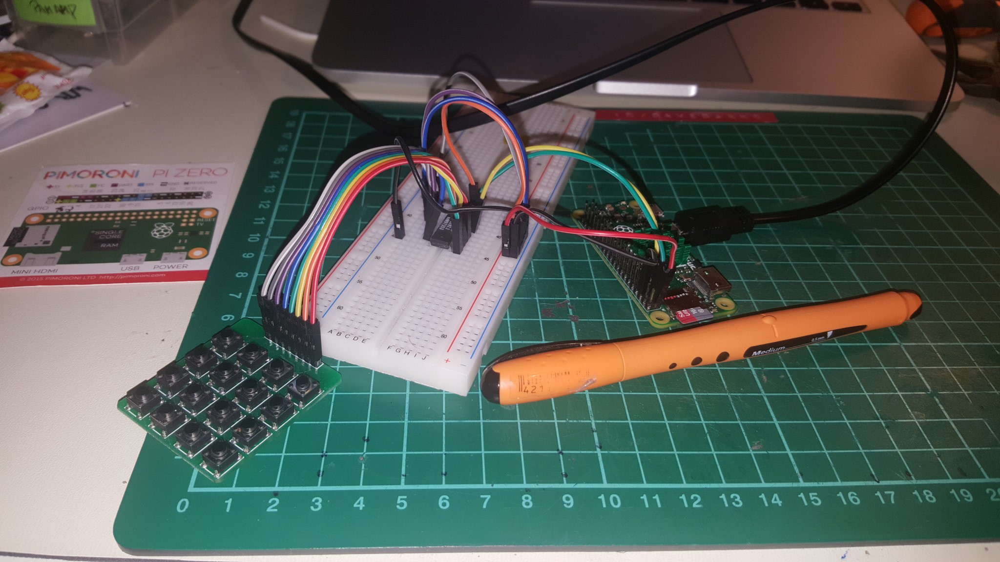
11/01/2016 at 22:29 • 0 comments![]()
It took me a while to get this far and I'm even further away from being done. I couldn't find a good example how to use the I2C library for it. http://wiringpi.com/reference/i2c-library/
As I understand now, the function wiringPiI2CSetup gives you a file handle (everything in linux is a file, right?) and you need to store it! That's what I'm doing with the fd variable. Ignore the broken math, it's what I got from 4 hours raging on the keyboard after hours of work. From there you can use the fileHandler thing to read and write from and to. This way I got some data from a 4x4 keyboard.
Little console helpers:
i2cget -y 1 0x20
i2cset -y 1 0x20 0x87
gpio i2cd
I also messed up the PCF8574 addressing pins :D of course I did. Here's my messy script.
#include <wiringPi.h> #include <wiringPiI2C.h> #include <stdio.h> int fd; int rpl; int row = 1; int col = 16; int main (void) { fd = wiringPiI2CSetup(0x20); wiringPiSetup (); for (;;) { if (row>8) { row = 1; col = col << 1; if (col>128) col = 16; } rpl = wiringPiI2CWrite(fd, 240-col+row); int b = wiringPiI2CRead(fd); // printf("\t%i", 240-col); // printf("\t%i", row); // printf("\t%i\n", b); if (b != 240-col+row) { printf("\t%i", b); printf("\t%i\n", 240-col+row); delay(250); } // delay(250); row*=2; } return 0 ; } -
Updated 3D printing files
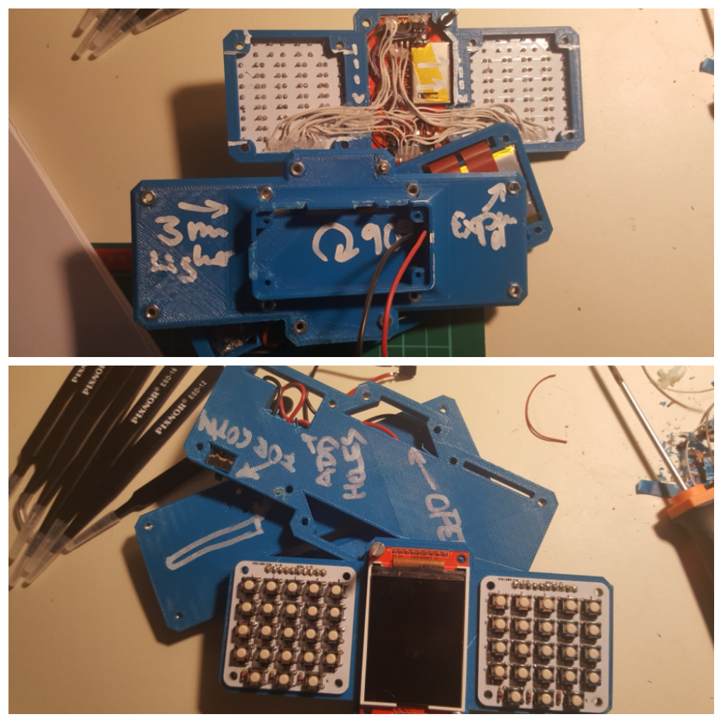
10/31/2016 at 19:16 • 2 commentsYou can now download an print along :D only thing missing is the cover for the raspberry PI bottom. Notes came in handy.
![]()
Portable Raspberry PI Zero
a 3D printed portable computer with a QWERTY keyboard