Close
0%
0%

RV Battery Monitor

This project will monitor RV batteries while it is in storage.

Similar projects worth following
Have you ever forgot to turn your batteries off in your RV and they went dead? This project will read the voltage of both of the RV house batteries as well as the engine starting battery and send the data hourly to ThingSpeak. An email message will be sent as an alert when the battery drops below a set voltage. The project will run from a dedicated power pack.

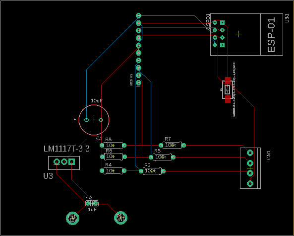
The "RV Battery Monitor" uses a ESP-01 and a ADS1115-4-Channel-16-Bit-I2C to read the voltage of up to 4 batteries.  Battery voltages are uploaded hourly to ThingSpeak for storage and graphing.  An alert email will also be sent hourly if any of the  battery voltages drops below a set value, in my case 12.4 volts. 

Graphs can be seen here: https://thingspeak.com/channels/870224

RV Battery Monitor.brd

Eagle CAD Board file

brd - 67.21 kB - 10/25/2019 at 13:12

Download

RV Battery Monitor.sch

Eagle CAD Schematic file

sch - 444.97 kB - 10/25/2019 at 13:12

Download

RV-battery-monitor-r13.ino

Arduino code

ino - 8.36 kB - 09/19/2019 at 12:27

Download

  • 1 × ESP-01
  • 1 × ADS1115-4-Channel-16-Bit-I2C
  • 1 × LD1117 3.3
  • 1 × 10uF capacitor
  • 3 × 100k resistor

View all 10 components

  • 1
    Step 1

    I used the "CircuitSetup Solderable Breadboard" and mounted the ESP-01 on a 2x4 header.  It is easily removable for programming.

View all instructions

Enjoy this project?

Share

Discussions

Nuukem wrote 07/21/2020 at 05:19 point

Thanks for posting this.  Would you please post a photo of the completed board?  I'd like to see how you wired it up.

  Are you sure? yes | no

Marcrbarker wrote 03/26/2020 at 14:48 point

Another hint is if you require finer ADC resolution, (you're likely only utilising 1/3 of it) consider configuring your ADC to operate "supressed-zero". I've got an example of this on one of my projects here.  A 10 bit ADC count range 0 to 1023 would equate to 11.0 V to 16.12 V = 5 mV per bit.   

  Are you sure? yes | no

Marcrbarker wrote 03/26/2020 at 14:02 point

Hi, if the monitoring device is consuming a significant current because its 12 V supply is on the same supply you're monitoring the main culprit will be the 3-terminal regulator. Don't forget it consumes energy while the microcontroller is sleeping.  Power the circuit instead from a single cell lithium and let it take cycling instead.

 Whenever the microcontroller wakes up and sees RV battery voltage > 13 V  then it connects a charger from the (also charging) 12 V circuit to top up the lithium battery. Possibly a relay and even re-utilising the regulator modified as a crude charger.   

Bear in mind that if you presently reference your ADC from the 3.3 V stabilised power rail you would also need to add a voltage reference because the voltage on the lithium will typically vary +/- 0.25 V  of 4 V. 

  Are you sure? yes | no

Karl-Wilhelm Wacker wrote 09/12/2019 at 20:15 point

same as my earlier comment about the FETs - the circuit will bias itself off when the ESP8266 is off

  Are you sure? yes | no

Karl-Wilhelm Wacker wrote 08/26/2019 at 15:53 point

Use a P-type FET like the IRLML6402 as a hi side switch - tie the source to the voltage you wish to monitor, the drain to the resistor divider and a pair of 10K or so resistors - one between the gate and source to bias it off, and the other between the gate and the drain of a 2n7000 fet, with the 2n7000 source tied to ground, and the gate to 2  resistors, a 10k to ground, and a 1K to the micro pin that goes high to enable the divider.

  Are you sure? yes | no

rockfishon wrote 08/26/2019 at 16:43 point

Thanks for the idea.  I am now thinking of using very high value resisters to reduce the current flow and just leave them connected all of the time.  Something like 500k and 100k.  That should draw 25uA if I calculated correctly, which is nothing to a large 12v battery.  I think that will work since the input impedance of the ads1115 is many meg ohm.

  Are you sure? yes | no

Karl-Wilhelm Wacker wrote 08/26/2019 at 16:46 point

Don't forget a cap 0.1uf ceramic across the lower resistor for noise suppression and to handle the current draw of the ADC during the conversion cycle.

  Are you sure? yes | no

rockfishon wrote 08/23/2019 at 11:41 point

I am trying to figure out how to engage a voltage divider so that it is not always drawing current while the ESP8266 is in deep sleep.

  Are you sure? yes | no

TheGrim wrote 09/23/2019 at 20:17 point

Look at this project. I build this with kids at the library. Control the bottom of the divider with a NPN transistor to disconnect ground when you want to do so. 

http://rsg-electronics.com/wp-content/uploads/2019/08/NightLight_006.pdf

Basically interrupt the path of the current at the bottom of the divider and only engage it when you need to do so.

  Are you sure? yes | no

Similar Projects

Does this project spark your interest?

Become a member to follow this project and never miss any updates