Close
0%
0%

FiberGrid

FiberGrid is a sensor framework for robotics

Public Chat
Similar projects worth following
FiberGrid is an inexpensive open source 3D printed optical sensor framework for robotics. If you don't want to spend years learning about electronics, how to interface sensors to microcontrollers and DSP but you are ready to jump into action, this project is for you! Forget Raspberry PI, arduino, PICs and other MCUs. There is an easier and much cheaper way to add sensors to your projects. Add hundreds of 3D printed mechanical ANALOG sensors for the price of cheap plastic optic fiber. The goal of this project is to take electronics out of the picture and allow everyone around the world to build sophisticated devices. You can build robots, interactive art, home security systems, arcade machines, computer and music keyboards, prosthesis, VR gloves and much more!

Here is a video that explains how FiberGrid works: https://cdn.hackaday.io/files/1673177158490528/fg%20explained.mp4

How it works

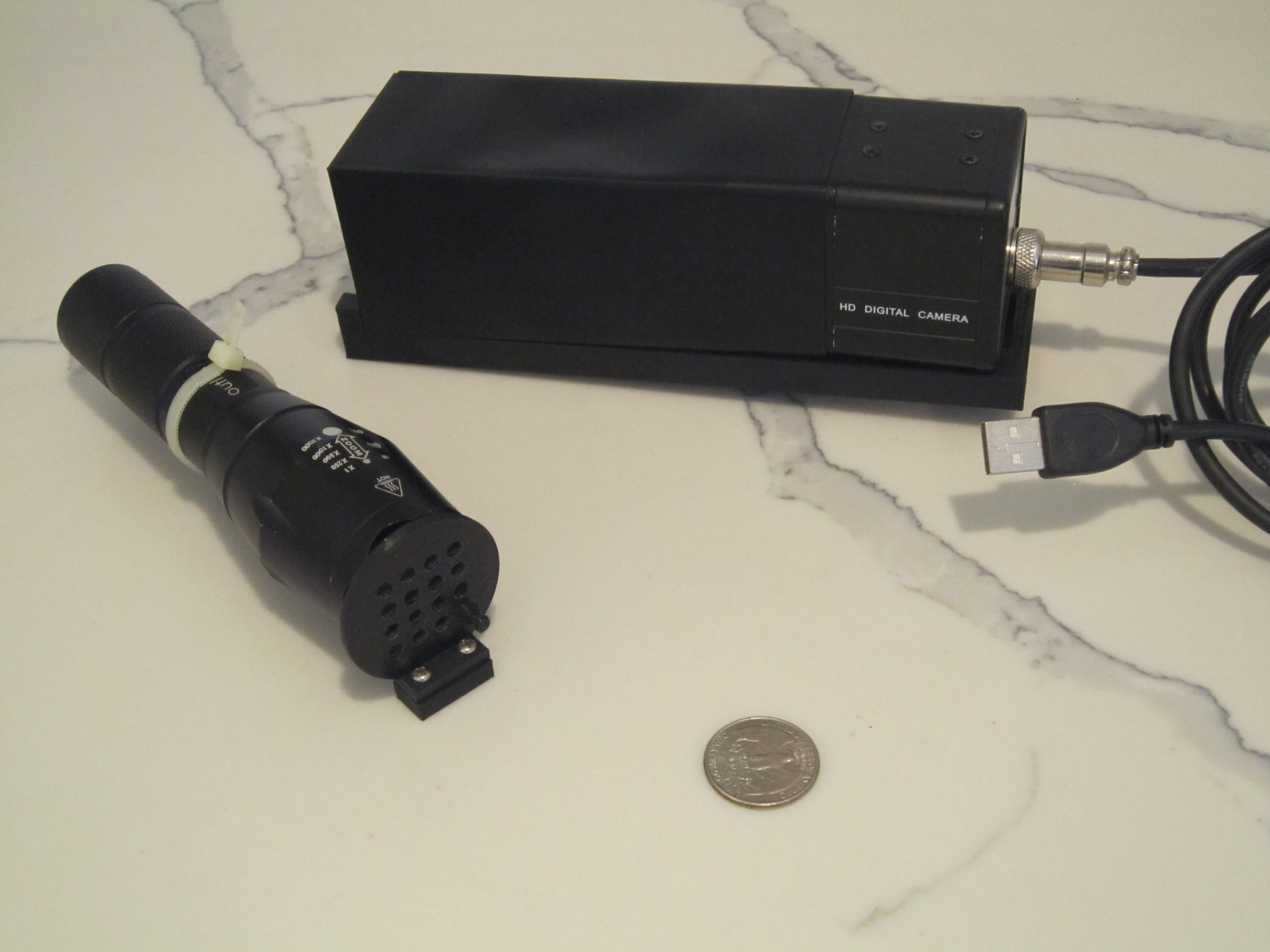
Fibergrid hardware consists of two parts: a lightsource and a camera with an enclosure.  They are connected to 3D printed sensors by inexpensive plastic fibers.  The light source shines light on a grid with exposed fiber ends.  Fibers transmit light to your light blocking sensors.  What light remains is picked up by another fiber that transmits it to the camera enclosure. Camera software running on your PC, laptop, tablet, phone, Raspberry PI or anything that has or can interface with a camera converts each incoming fiber's light to a number.

You design the sensors based on the principle of blocking light.  Alternatively LEDs can be placed within individual sensors.  In either case, FiberGrid is able to sense how much light a mechanical sensor blocks and give you a value in software as a continuous range not just an on/off flag.

A single FiberGrid camera can simultaneously read values from HUNDREDS of "analog" sensors.  Many more than the number of ADC channels in any MCU!  This eliminates the need to communicate among multiple MCUs.  You do not need any band or low pass filters as you would for some ADC channels.  No debounce circuits for interrupt triggering pins.  No scheduling (waiting) for ADC completion in firmware.  Read-modify-write problem will not haunt your in your sleep.  No back EMF on your power rail to deal with.  No worrying about induced currents.  Schmitt trigger is gone from your vocabulary.  You no longer care about TTL and CMOS logic difference.  Floating open collector who?  Pull up, pull down, reference voltage, resistor ladder what?  Time the discharge of a cap through a pot on a digital pin never again.  No more explaining all of the above to ten year olds in STEM, just give them a glue gun and let them make stuff with sensors!  Don't have a USB cam and a computer or a Raspberry PI?  Use your phone - those cameras are pretty good and OpenCV is supported on Android!

If you want to make suggestions or need help, reach out to me at toAndrey(at)yahoo(dot)com.  Also I place this project or any code associated with it into public domain so feel free to modify it in any way, shape or form.  However I make no guarantees of any kind.  Use it at your own risk.  Any information provided here is for educational purposes only!  Do not blame me because your security system utilizing this technology failed and your Ferrari was stolen.

How the software works

There are two parts to FiberGrid software.  FiberCal is a calibration program that finds centers and bounds of the fibers in the camera's visual field and saves this information in a file.  Second is the FiberGrid "driver".  It uses the config file and provides a simple API for reading your sensors.  

The location of the fibers should never change if you have made the hardware device properly.  This allows me to separate the driver and calibration software for two reasons.  Detecting fibers can be done more accurately with human interaction.   The second reason is portability.  The driver could probably be written in 50 lines of python or java or C# code or re-written in C++ without using OpenCV.  Meanwhile the calibration utility does not need to change.  Let me re-iterate: once you know the locations of the fibers in your device that hopefully will never change, you can write a program to capture images and covert pixel brightness to values using your favorite programming language in a few lines of code!
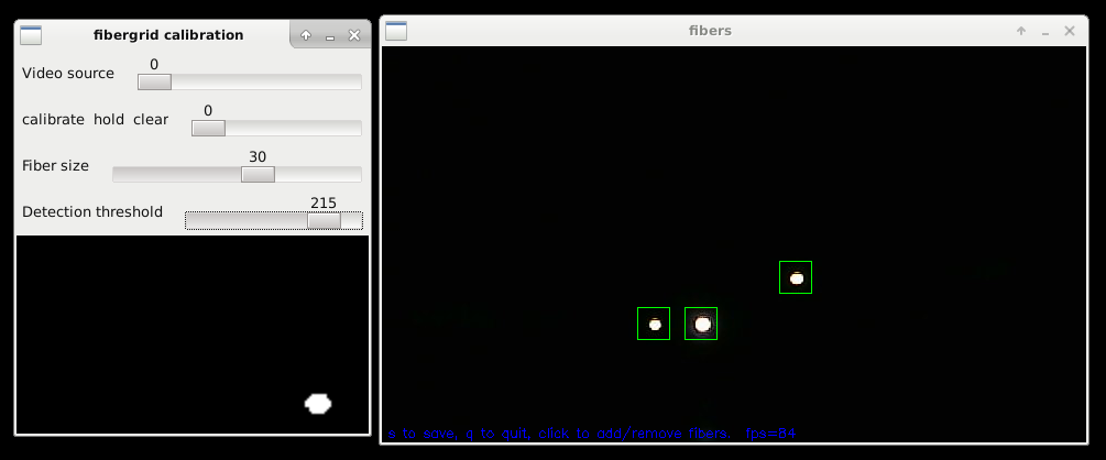
Here fibergrid calibration utility (fc) is detecting 3 fibers in the grid.  Image on the left is a closeup of one of the fibers.  You have an ability to change the fiber detection threshold, fiber visual size and add or remove fibers manually by clicking.  You should configure fibergrid to collect light anywhere from 9 to 100...
Read more »

fg explained.mp4

Explans how FiberGrid works.

MPEG-4 Video - 48.08 MB - 11/06/2021 at 08:55

Download

fibergrid_encoder_bracket.zip

Zip Archive - 67.51 kB - 09/06/2019 at 01:38

Download

IMG_3783.JPG

JPEG Image - 2.70 MB - 09/06/2019 at 01:01

Preview

fibergrid_board_cam.zip

Zip Archive - 148.77 kB - 08/27/2019 at 20:08

Download

fibergrid_board_cam_grid_3759.JPG

JPEG Image - 2.62 MB - 08/27/2019 at 19:55

Preview

View all 28 files

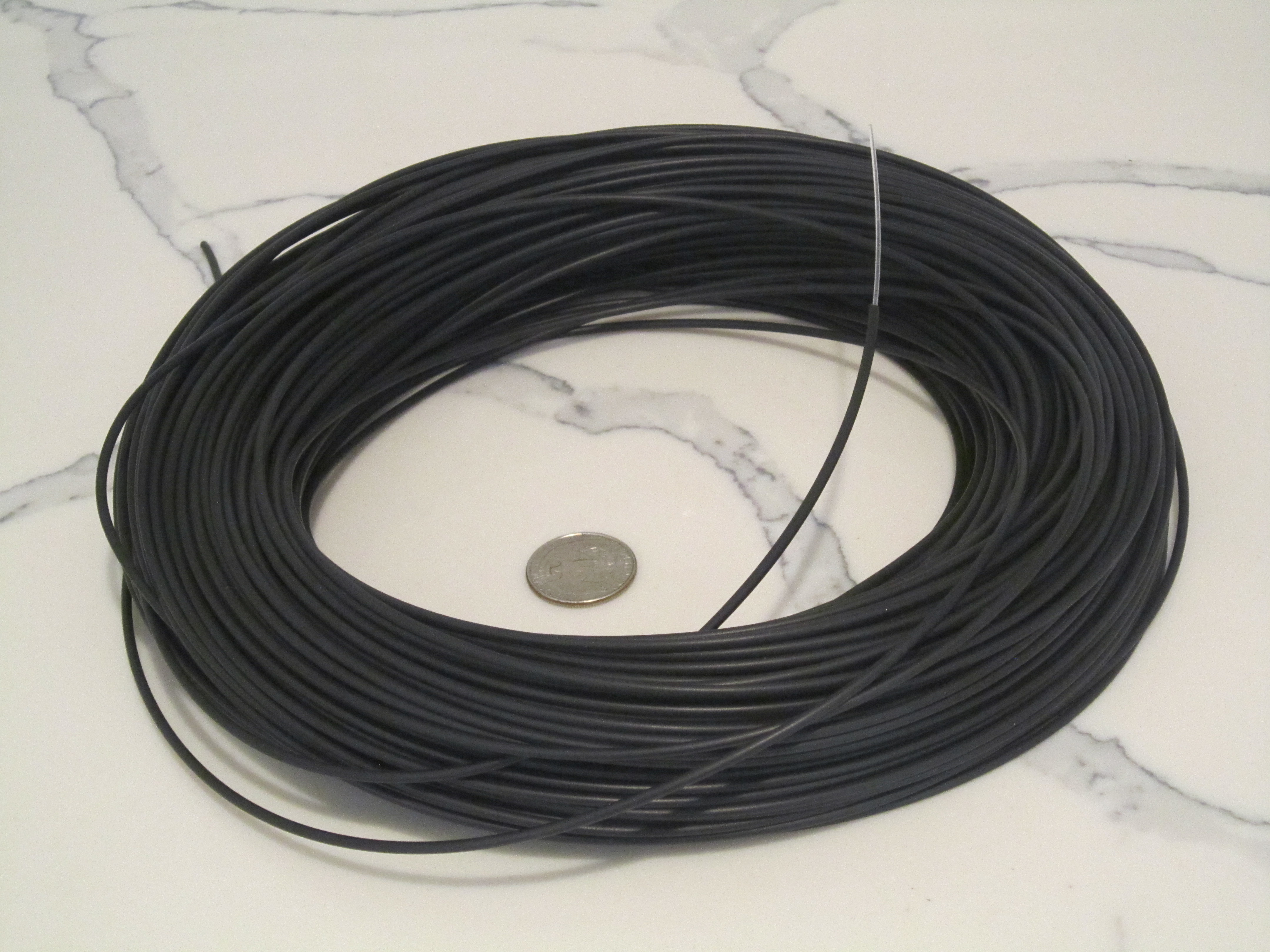
  • 1 × Plastic fiberoptic cable Cheap plastic insulated end glow optical fiber. I bought 100ft of 1 mm black jacket star ceiling optic lighting fiber for about $22USD from aliexpress.com It consists of a very loose-fitting jacket over a plastic core.
  • 1 × USB camera Depending on your needs it can be a $5 usb cam or a Raspberry PI cam or in my case a $65 Kayeton Technology 330fps at 640x360 with a 4mm manual focus lens usb camera from aliexpress. Camera framerate is important but resolution is not! High FPS allows FiberGrid to read sensor values at a higher rate. Camera needs to be able to focus on objects close to the lens (1 to 3 inches). Manual focus lense is the best.
  • 1 × LED or USB LED lamp USB LED lamp or a small flashlight. Do not use lasers as they can burn out the sensors in your camera!
  • 1 × 3D printer and BLACK PLA filament A 3D printer and BLACK PLA for printing all components. Black PLA is used to block ambient light.

  • Event Cameras

    rand328909/02/2021 at 03:36 0 comments

    Fiber Grid is almost made for event cameras:

    https://en.wikipedia.org/wiki/Event_camera

    https://inivation.com/wp-content/uploads/2021/08/2021-08-iniVation-devices-Specifications.pdf

    Pixel wise they have 320x240 to 640x480 resolutions.  They have 1 to 200 us (microsecond) temporal event resolution but they are very expensive.  For that price I'd rather use 100-200 discrete optical components.  When people realize how cool these cams are and they fall in price due to mass production though...

    When Fiber Grid will be used with Event Cameras, it will demonstrate the right way to do multisensory integration.  This will change what AI researchers feed to their models and hopefully get us closer to AGI.

    https://en.wikipedia.org/wiki/Multisensory_integration

  • Python driver

    rand328910/02/2020 at 10:34 0 comments

    I've added a python driver available here:

    https://github.com/rand3289/FiberGrid/blob/master/fibergrid.py

    As promised it is about 30 lines of code.

  • Where are all the sensors at?

    rand328907/25/2020 at 05:27 0 comments

    I've created a little demo for this technology.  It took me just a few hours to make it:
    https://hackaday.io/project/172309-3d-printed-joystick
    There seem to be many followers of this project, however no one has actively took an interest by building anything.  All it takes is a $5 USB cam and some cheap fiber guys...  Unless YOU create sensors, this project is not going anywhere !!!  What happened?  Is it too complicated or there is a boundary to entry?  I think it's simpler than learning how to solder and program MCUs.  Let me know what's up by sending me a PM  or email: toandrey (at) yahoo (dot) com    I am lost here.

  • Optical encoders

    rand328909/06/2019 at 01:13 0 comments

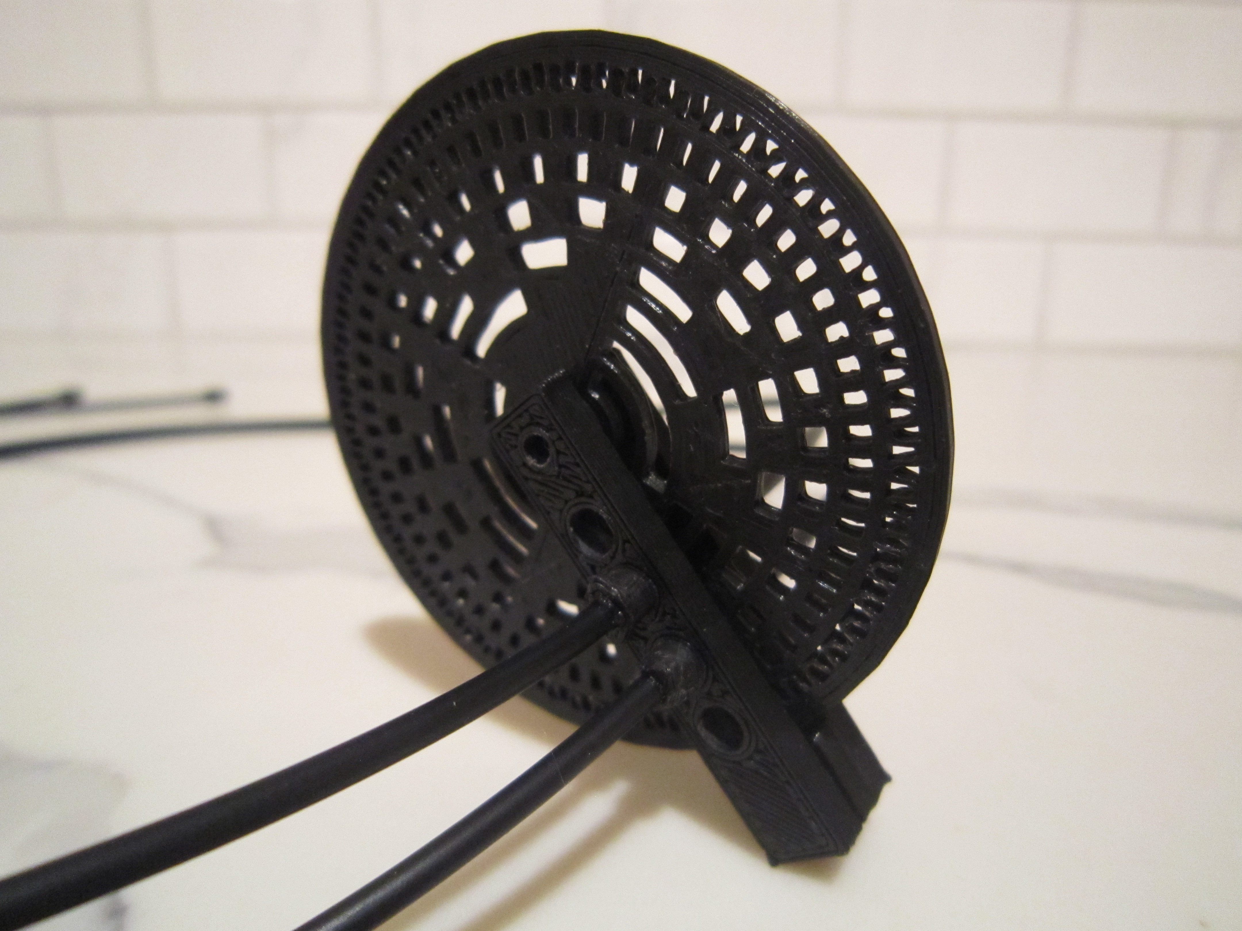
    Optical encoders are the easiest sensors to use with FiberGrid!  Here I am testing an encoder with two fibers attached to it

    In the future, I will make an encoder wheel with pegs out of alignment in order to place tracks close together. It will also have slits narrowing towards one end to block more light and increase precision.  For now I've taken an existing encoder wheel I've found on thingieverse and created a bracket that fits fibergrid plugs.  Bracket can be downloaded here.

  • Fibergrid enclosure for board cameras

    rand328908/27/2019 at 20:10 0 comments

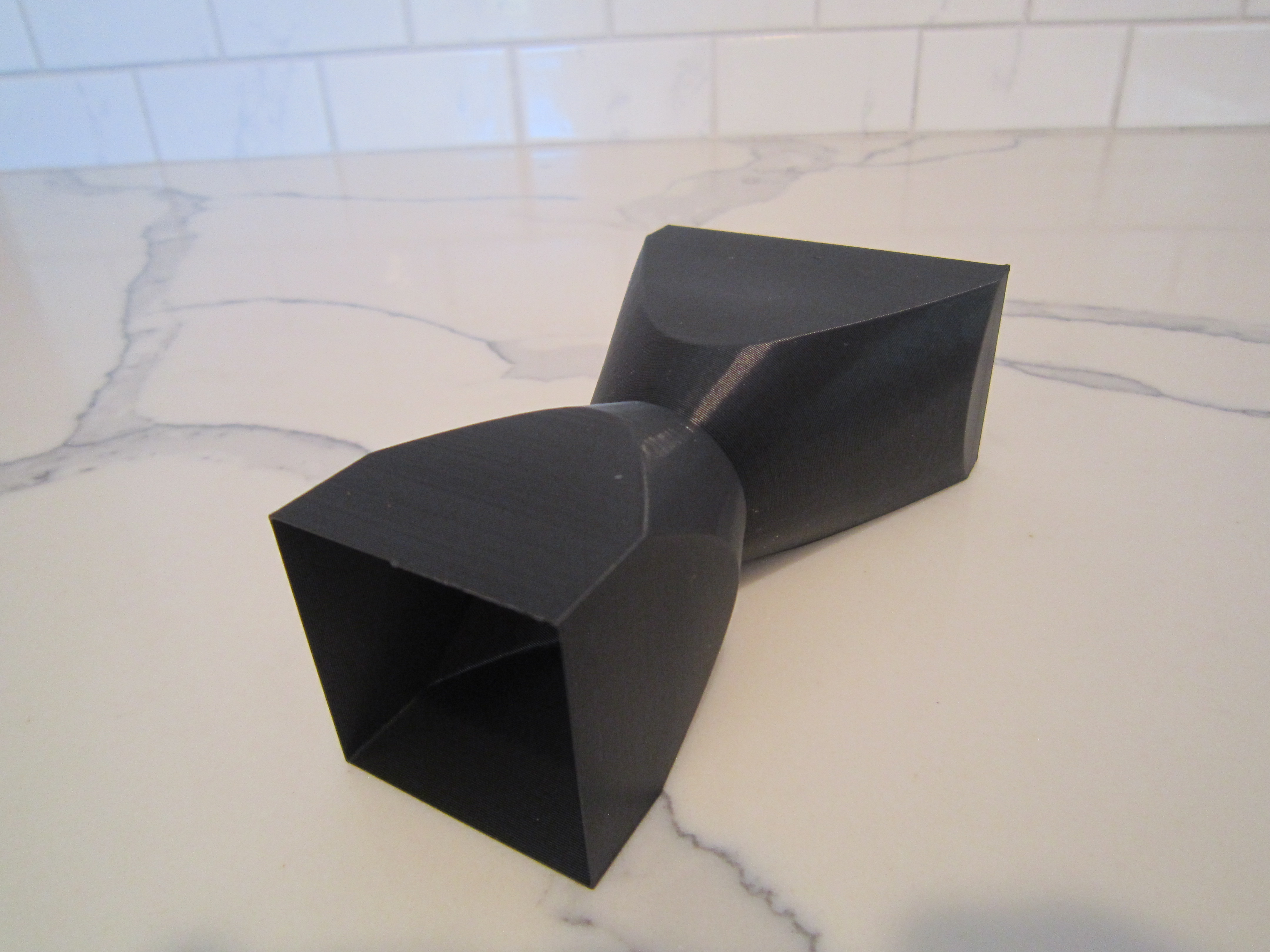
    I am working on a one-piece (grid attached to shroud) version for a board camera.  fibergrid_board_cam.zip  For now it has one plug hole.  It prints under an hour in vase mode. It can also be printed as a multi-layer shell.


  • Request for information

    rand328908/25/2019 at 01:46 0 comments

    Computer mice have optical sensors in them that have hundreds of pixels and internal framerates of thousands of frames per second.  Many of them allow raw image readout.  Reading them at high FPS is another story.  I've heard about read speeds of only 10fps over serial.  At that speed mouse sensors could only be used to add FiberGrid support to low end MCUs without USB.  If you succeed at reading any mouse image sensors at 30 fps or higher using any bus or find inexpensive high fps cameras or CCD/CMOS image sensors, please let me know!  Would TOF cameras be any good for this?

    Another possibility are CMOS linear image sensors. (Toshiba or Espos)  The problem is focusing hundreds of fibers on a short (8 to 30mm) narrow window.  You need an MCU to control them.  With linear sensors you no longer need FiberGrid software.

  • Please share your sensors!

    rand328908/25/2019 at 01:45 0 comments

    Please share your sensor designs!  Send me a link to your creations or pictures and suggestions to toandrey(at)yahoo(dot)com

View all 7 project logs

  • 1
    Software

    Software is available here: https://github.com/rand3289/FiberGrid

    Git clone. Change to the directory and type make.  Build the hardware and connect it to your computer.  Run fc (fiberCal) and generate fiberinit.h by pressing "s".  Play with fc sliders to get the best fiber detection (green squares around fibers).  Add fiberinit.h, fibergrid.h and fibergrid.cpp to your project or run ft (fibertest.cpp).  Use FiberGrid::read() or FiberGrid::readNormalized() to get sensor values!  Run your project to see the sensor values on a debug screen.  Comment out FIBERGRID_DEBUG to disable driver debug screen.  Currently both fiberCal and "the driver" programs rely on OpenCV library being installed to read the camera.

  • 2
    Making the hardware

    There are two versions of FiberGrid.  One for R&D and testing.  It features detachable fibers that can be disconnected from the grids.  Both fiber ends are glued into small 3D printed connectors.  The second is a "production version" where fibers are glued directly into the grids of the camera and light modules on one side and have a connector (plug) on the other.  This allows packing more fibers into the grid.  The diameter of the connector is greater than a plain fiber and takes up more grid space.  I am using a 1mm fiber.  If you need more than 200 - 300 sensors, try using 0.5mm fiber.  It should allow for a denser grid.  


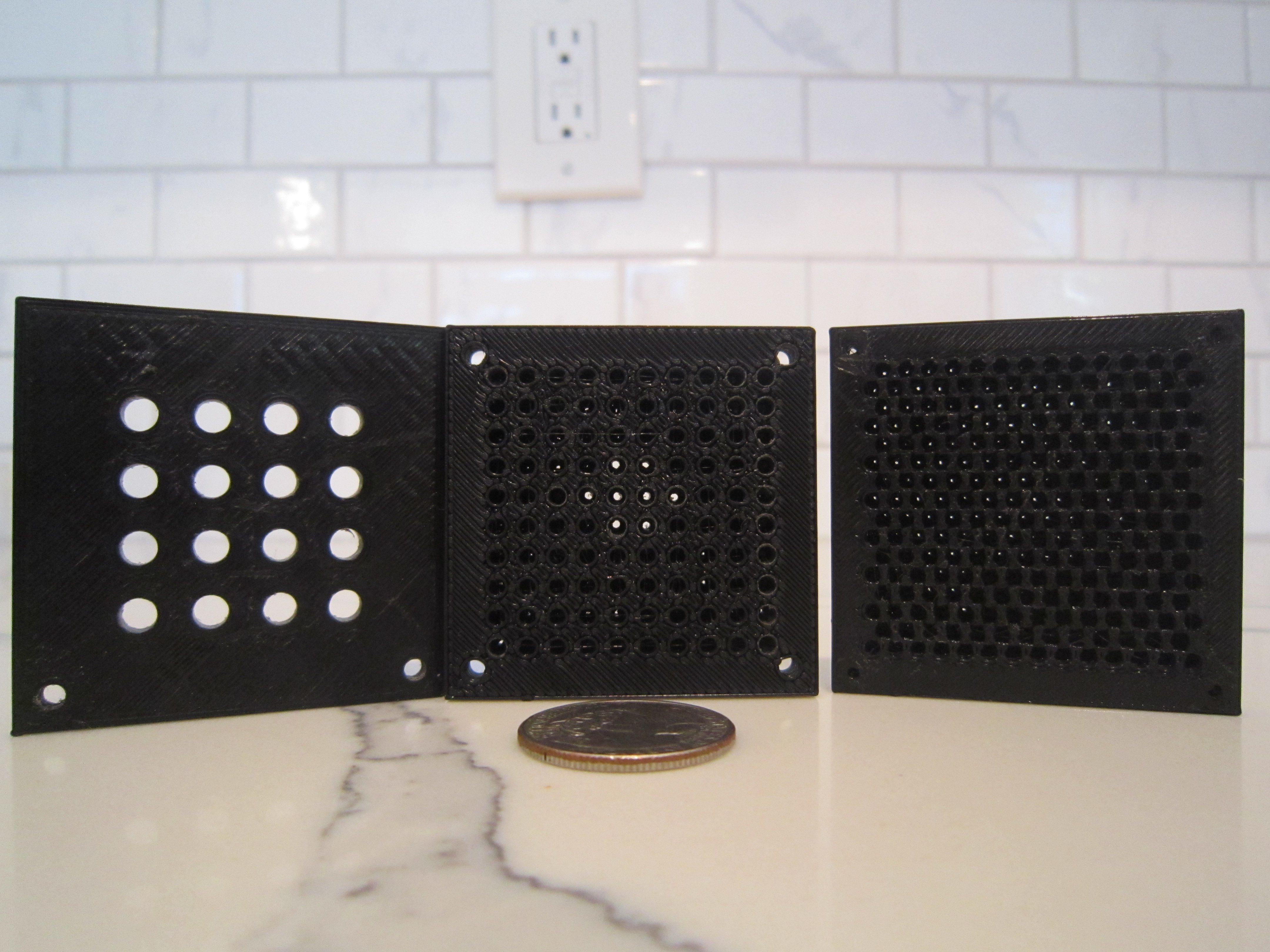
    * Choose between the two designs. Current R&D version models allow for 16 or 86 connections to each module.  The "production" version has 100 and 216 hole plates.

    * Download FiberGrid 3D models and print the parts.  I used Creality Ender 3 to print my parts.  Cleanup the holes with a 1mm drill bit, a bit with diameter of your cladding and a ~4mm bit for large holes.

    * Assemble the light and camera modules as shown in the pictures below.

    * Cut the fiber into pieces of appropriate length depending on your project.  If you have chosen the R&D version, glue the connectors onto both fiber ends with superglue.  Otherwise glue one connector to one fiber end and glue the other end directly into the grid of the camera module.  Do the same for the light module fibers.  Plug unused holes with pegs (R&D version) or fill them with black silicone.

    * Print some sensors or design and print your own sensors with a 4mm diameter holes for fibers coming from the light module and going to the camera module.

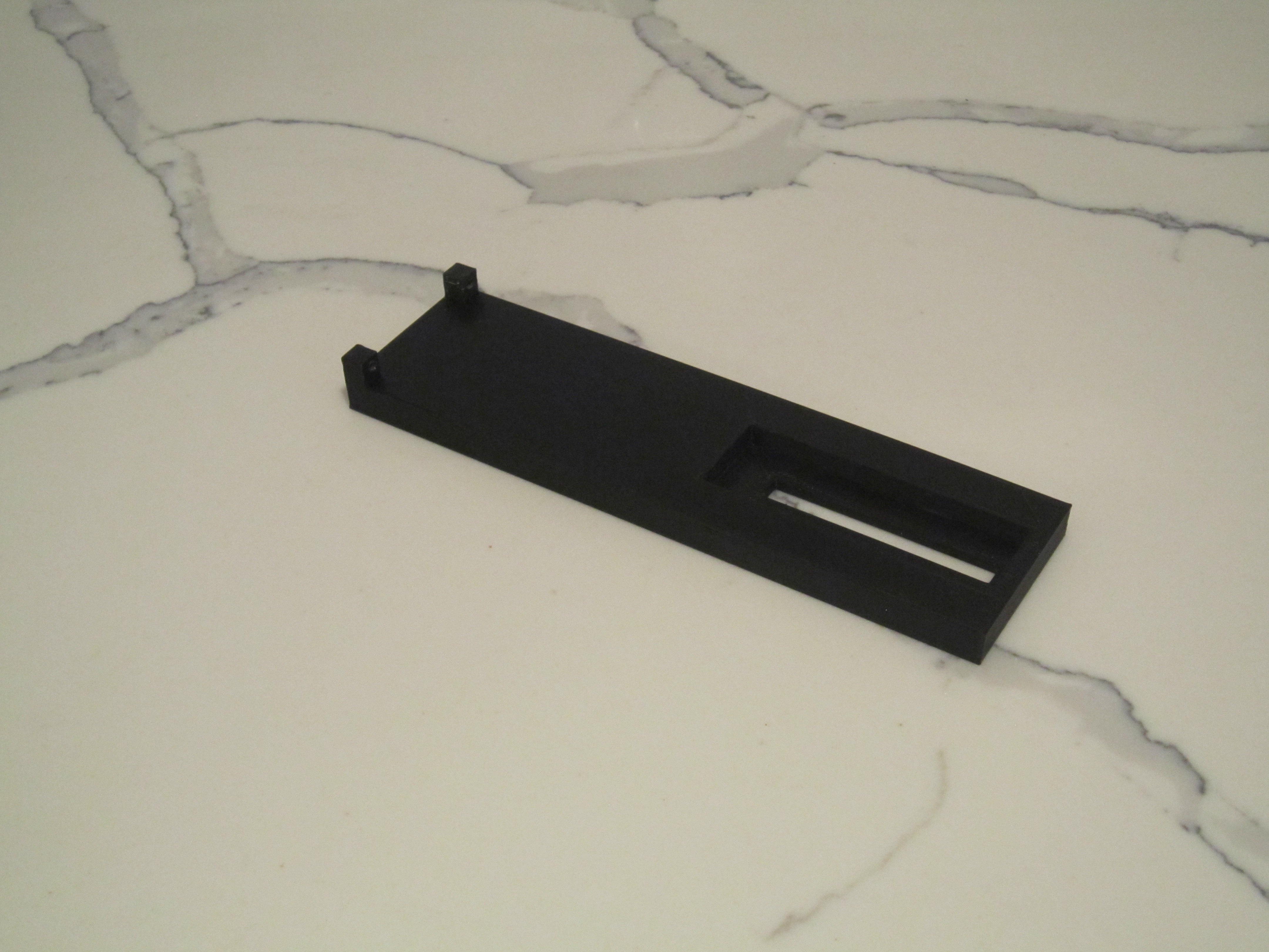
    fibergrid bench is the largest component and takes several hours to print.  Try using 20% infill and a 0.3 mm layer height.

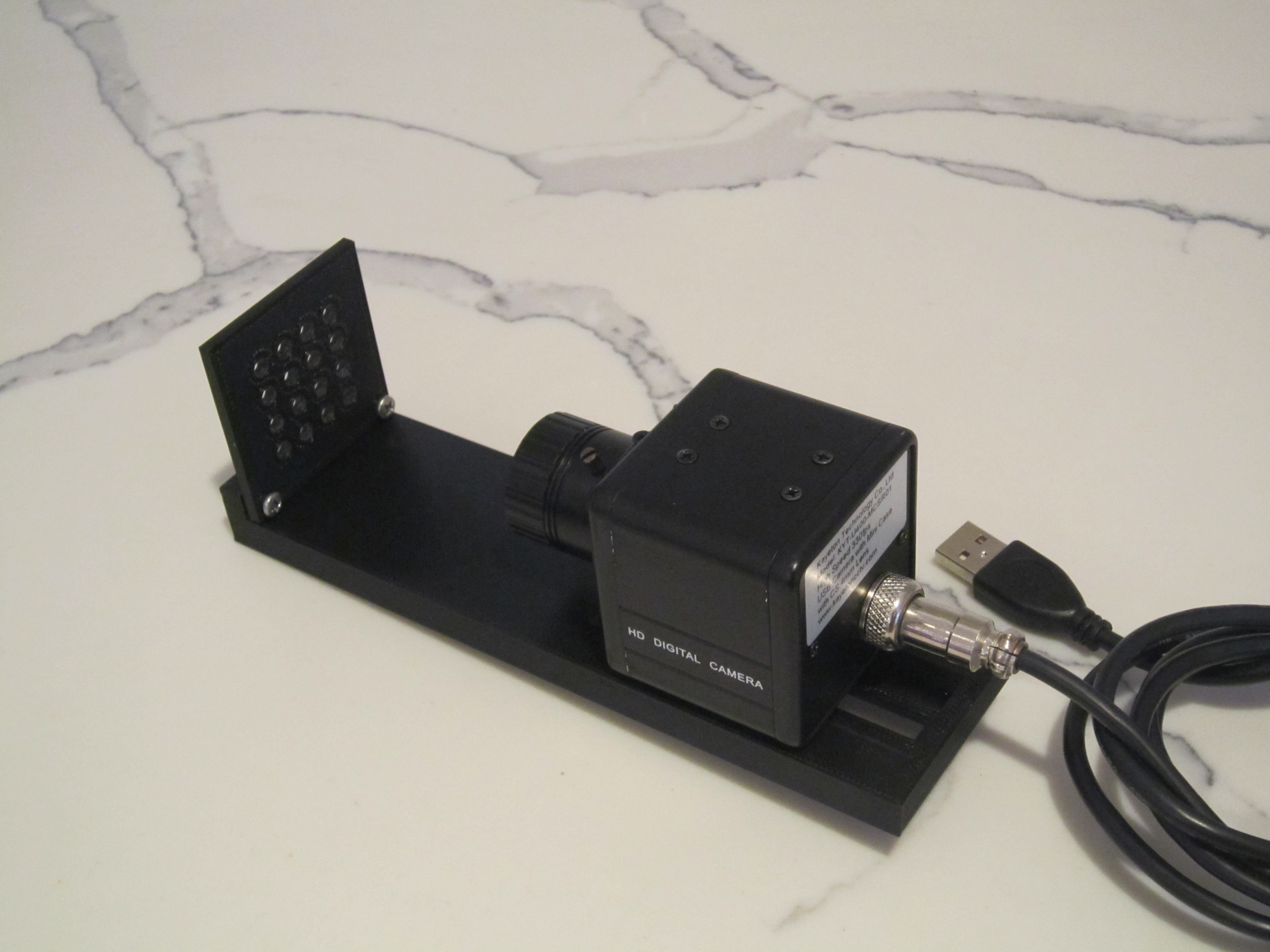
    The grid with 16 plug holes is attached to the fibergrid bench with two screws.

    In the picture above the camera is attached to the bench with a bolt.

    The shroud is pushed onto the grid and the camera slides into it. After that the camera bolt is tightened.

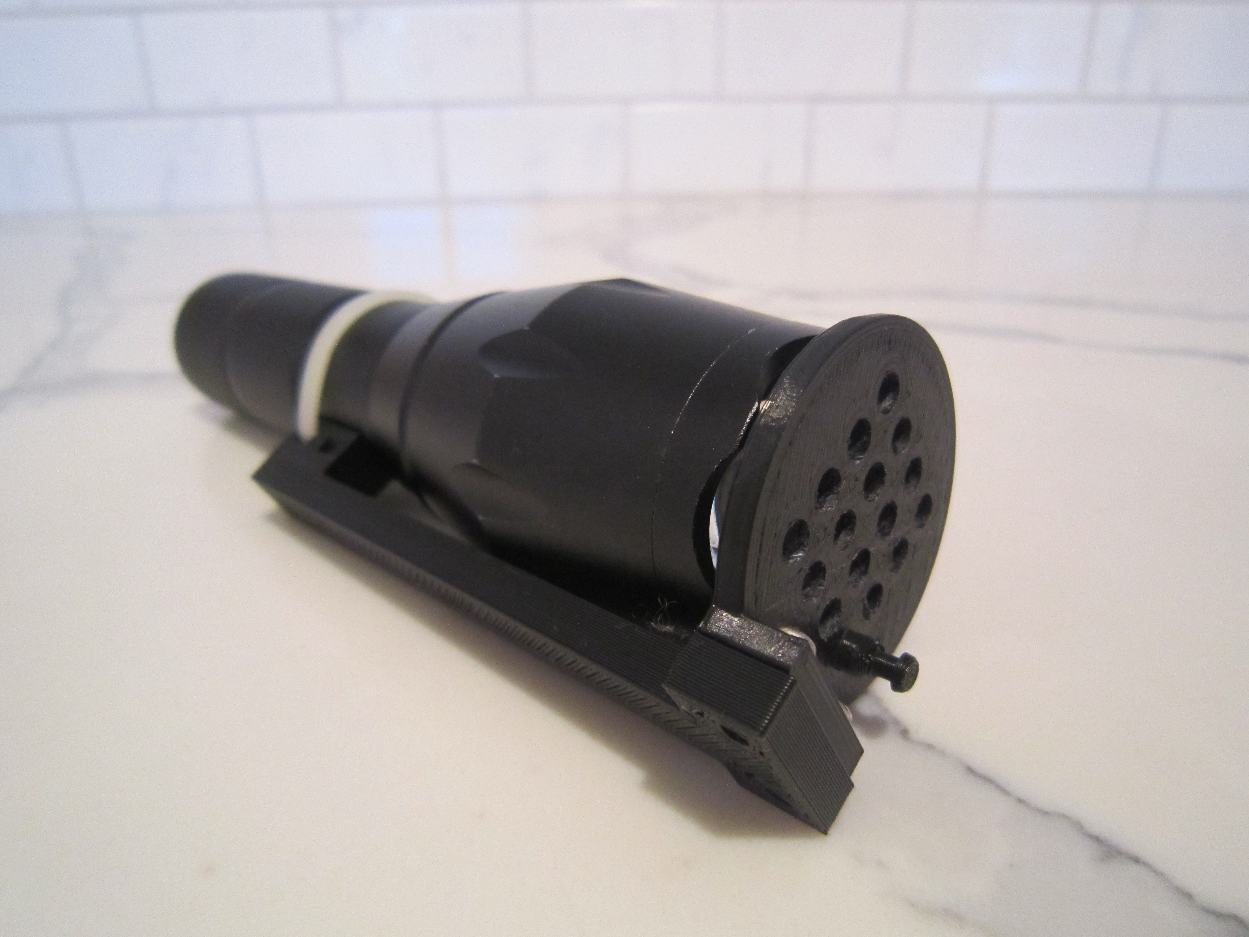
    Light module shown here is already assembled with two screws and a ziptie holding the flashlight to the base.  Flashlight front should not be touching the PLA parts since they can melt or deform.

    Closeup of the assembled fibergrid light module.

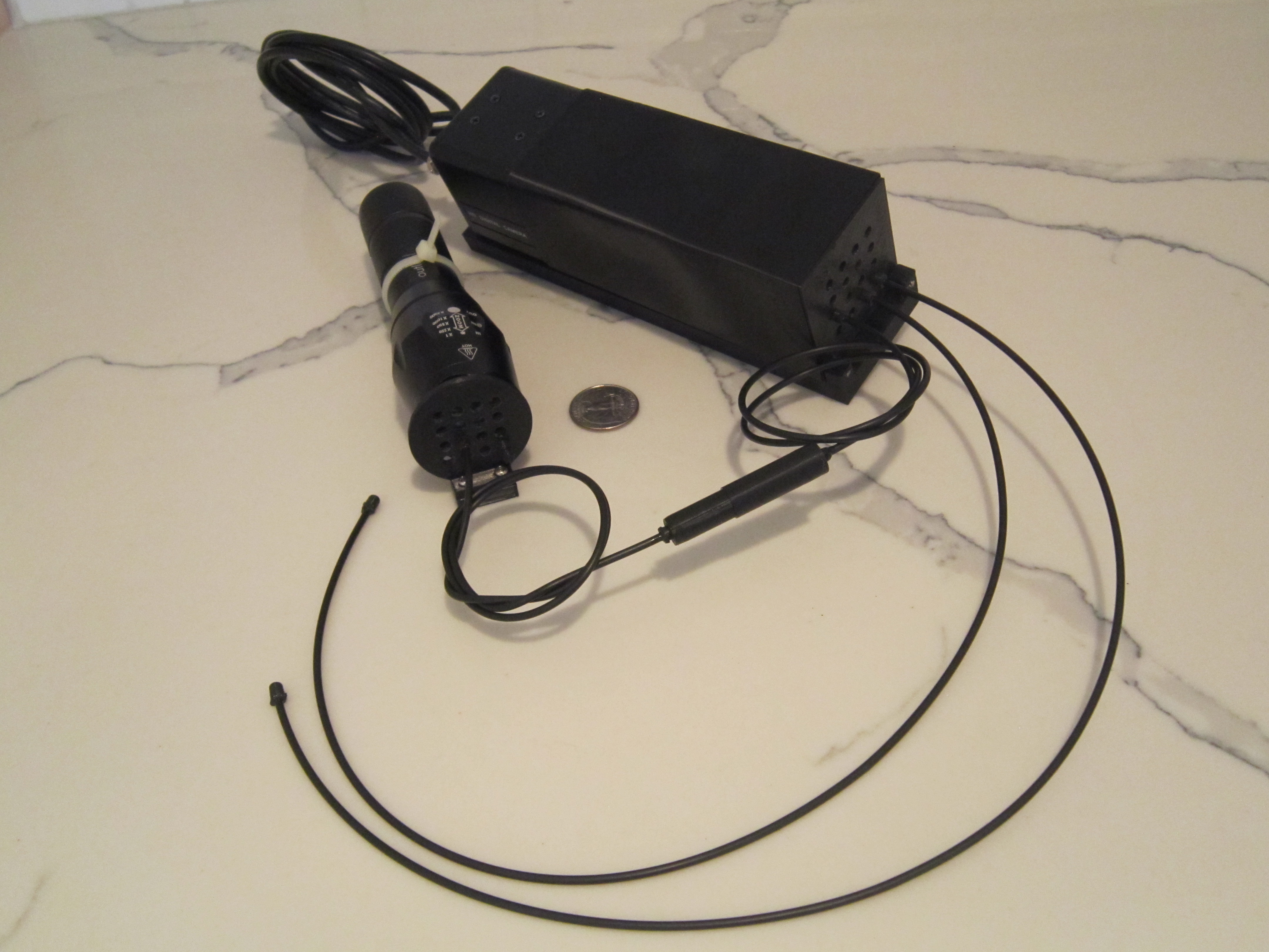
    Attaching the fibers to the light module and camera module.

    A sensor (fibergrid_sensor1.obj) is connected between the light and camera modules.

    Two more fibers are added to the camera module.

    This is my spool of 1mm fiberoptic cable.

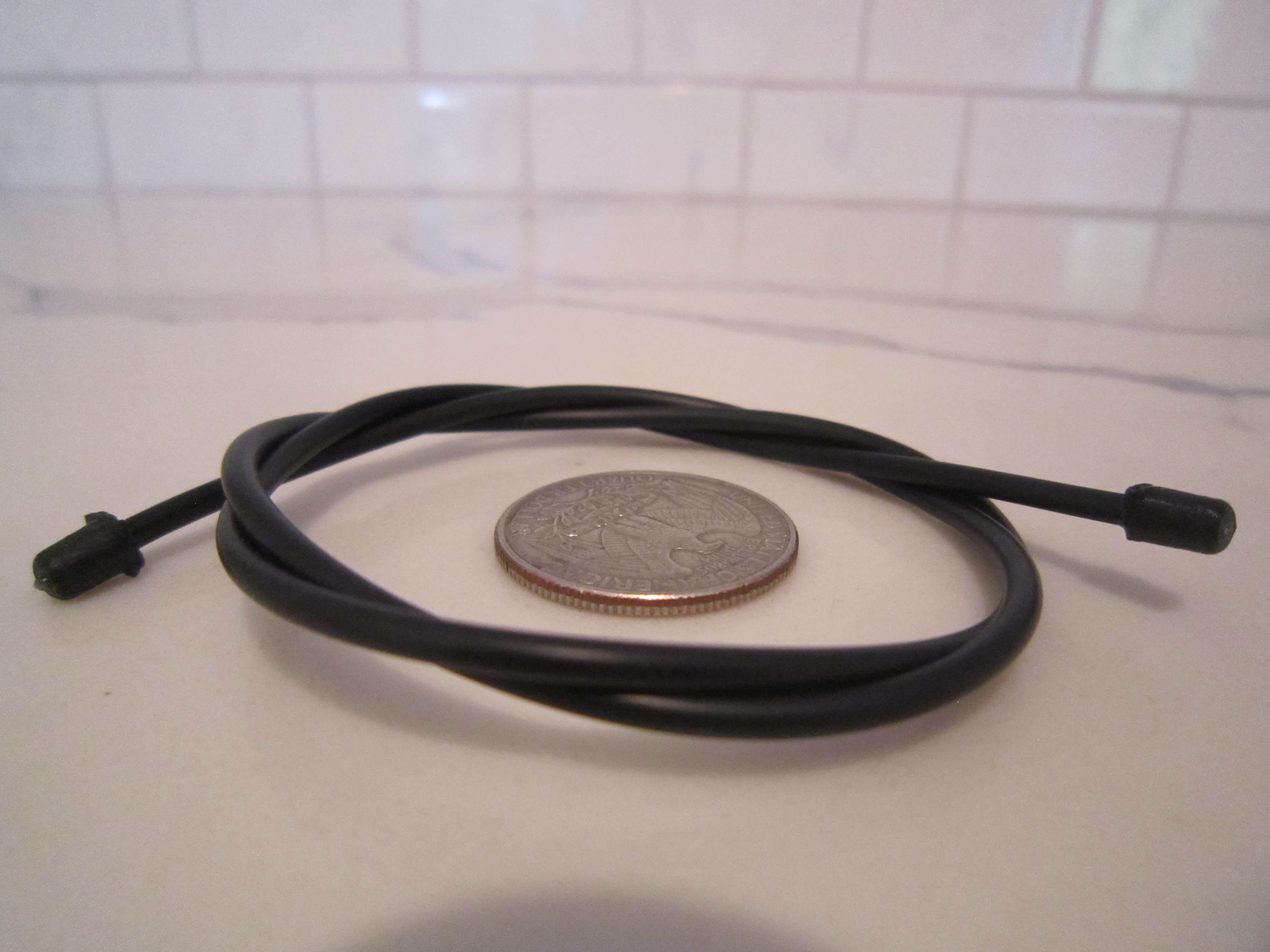
    A length of the fiberoptic cable with two plugs glued to both ends.  The fiber and the jacket are inserted into the plug with a drop of glue in it.  After the glue sets, clip off the end of the fiber with scissors.

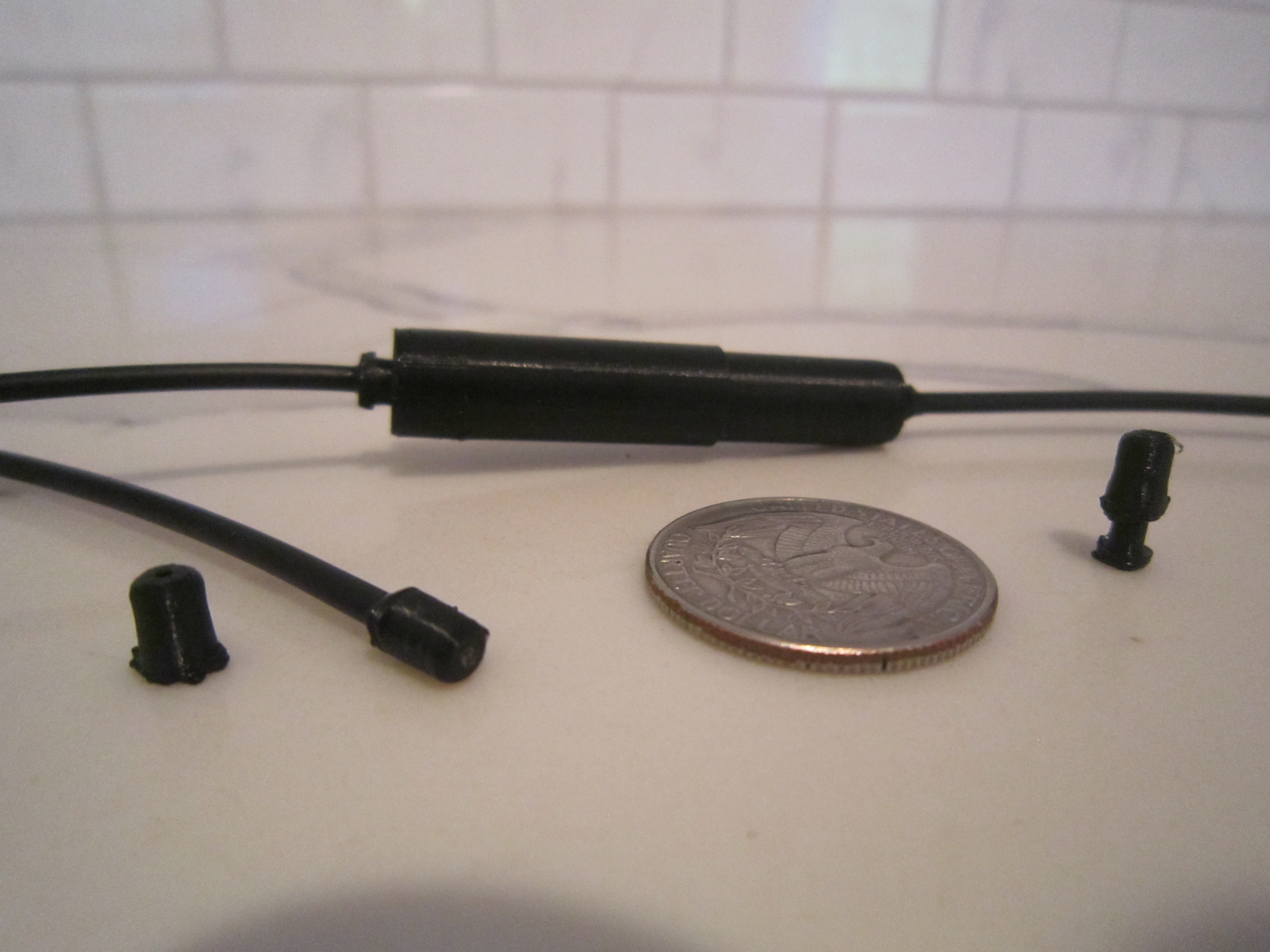
    Plugs, and a sensor in the background.

    Choices for the grid: 16 connectors, 100 holes, 216 holes.  In the two grids on the right the fibers have to be inserted and attached with glue directly.

  • 3
    Alternative construction techniques

    If you do not have a 3D printer, you can still play with this technology.  Bunch-O-Baloons water baloon straws are perfect for putting up to 37 fibers in a grid.  Fibers can be attached to individual straws with superglue.  Bunch-O-Baloons can screw onto a neck of a plastic water bottle making it easy to attach to any container with a light or a camera.  Glue the other end of the fibers directly into your sensors.  Paint everything black or wrap with black tape.


    As an alternative to Bunch-O-Baloons, drill holes with the diameter of your fiber through two sheets of black 3mm thick plastic.  Enlarge the holes in one sheet to the thickness of your fiber jacket.  Align the holes and glue the two sheets together.  Secure fibers into the holes with glue.  When the fiber is inserted it goes through both sheets of plastic, however the jacket will go in half way making a secure connection.

View all 6 instructions

Enjoy this project?

Share

Discussions

maxbit89 wrote 10/05/2020 at 07:34 point

Looks prety cool. Only thing that bothers me is the 3. section in your text. I understand that electonics some times isn't that easy to use. But this is not the solution to this problems. In the end there is all this stuff packet in the blackbox of the Webcam. Fiber optics and opencv have also their cons.

  Are you sure? yes | no

simplisticlines wrote 08/18/2020 at 21:43 point

Can you post a video of something basic to get a better understanding? I love this concept but I am struggling to see how it is easier then a sensor. I am super curious!

  Are you sure? yes | no

rand3289 wrote 08/19/2020 at 01:17 point

I guess I could make a video of how the blobs look on the screen when I turn the senosor.  Meanwhile looking at my joystick project could help:
https://hackaday.io/project/172309-3d-printed-joystick

It is "easier then a sensor" in the following ways:

1) you can 3D print all your sensors and don't have to buy them (delivery wait time and $$$)

2) you do not need to know anything about electronics !!!  For example condition analog signals (filtering / clamping / amplifying / scaling etc...)

3) It is possible to connect HUNDREDS of sensors to a single camera whereas you have to look very hard to find an MCU with more than let's say 40 ADC channels. 

  Are you sure? yes | no

Daniel Dunn wrote 07/25/2020 at 06:48 point

I wonder if you could do the same thing with LEDs and matrixing. 8 LEDs could get you 16 inputs, which is probably enough for a robot, and an Arduino could do it all.

I might actually try this, much as I love data busses, I can think of applications where fiber would have benefits.

  Are you sure? yes | no

rand3289 wrote 07/25/2020 at 08:39 point

I view robotics primarily as a platform for creating AGI.  Therefore robots need hundreds and thousands and millions of inputs to create rich internal state which will allow formation of higher level / abstract concepts.  This is the reason fibergrid was created.

Fibergrid gives you the ability to construct your own sensors!  And you don't need to know ANYTHING about electronics...

  Are you sure? yes | no

Eric Hertz wrote 08/26/2019 at 20:14 point

It's a weird-and-still-new to me era when image-processing is easier [and maybe even cheaper?] than using discrete photo-transistors. But it seems to be that way now, at least for some! Especially considering the ubiquity of devices and learning-tools with inbuilt cameras and limited GPIO.

This is an interesting and clever 'hack'/design/tool in that realm!

  Are you sure? yes | no

Similar Projects

Does this project spark your interest?

Become a member to follow this project and never miss any updates