land-boards.com
-
Interrupts from the MCP23017
11/03/2019 at 23:40 • 0 commentsThe MCP23017 has two interrupt modes. One is to interrupt on level. The pin is compared to a default value and causes an interrupt when different. The interrupt will persist as long as the signal is different than the default value that was set. Reading the GPIO or INTCAP clears the interrupt . But, in this mode another interrupt will happen immediately if the pin is still different That is the mode I was running and and explains why interrupts hang around until the button (front panel or Expansion MCP23017) is released.
The other mode causes an interrupt on change of the pin. That's the mode I switched to and it works. Interrupts are generated when there's a change. The only downside is there is an interrupt when the button is pressed and another interrupt is generated when the key is released. There's no edge selection for the interrupt but that's easy enough to do in the PSoC software. It could possibly be useful to know when a button is released
The interrupt takes a bit over 500 uS total time. That's due to the 400 KHz I2C bus speed and the number of ports (6x2) that need to be read. No biggie really.
At this point it would be helpful to read the values from the ports and create three values from them. One would be a long value which is the state of the Front Panelswitches. The other would be two bytes which indicate the value of the Expansion MCP23017 ports. The same caveats about debouncing apply here that applied when getting the Front Panel to work.
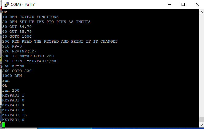
Here's the Polled mode reads of the JOYPAD from basic. The Z80 is reading the PIO Port A (that's where the JOYPAD is connected) and printing the value if it changes. This mode does not require interrupts since it's actually doing a read of the PIO.
Interrupts are funny things. When they happen at the wrong time bad things happen. The program above worked pretty good - some of the time. Then they would kill the program on the Z80. Difficult to debug in this setup since I don't have visibility into the Z80 code without hooking up the logic analyzer.
Allowing Interrupts in a Time Slot
There's a fix for this issue by limiting time interrupts to only happen in a window. And the main( ) program loop is a convenient place to do that. The code looks something like this.
            // Give the I2CInt a time slot
            I2CINT_ISR_Enable();
            CyDelayUs(2);
            I2CINT_ISR_Disable();
This opens a short window for the interrupts and it cleared up the Z80 hangs. The BASIC program does a constant read of the PIO port so it's likely the interrupt was messing up that read by interrupting the I2C transfer for the polled read. Doing the interrupt in a time that the Z80 port is guaranteed to not being handled is a fairly clean solution.
The 2uS delay is not necessary. Just enabling the interrupt would let it sneak through. I tested it and it worked fine without it.
Improvements
The PIO should not be directly read. No need to do that. The ISR can load the value of the port when the interrupt happens. After all, it is only reading the port when it needs to be read - when a button is pressed.
In the next log we'll take a look at Interrupts from the MCP23017 seen from the perspective of the PSoC and attempt to solve a problem that I am seeing.
-
JOYPAD
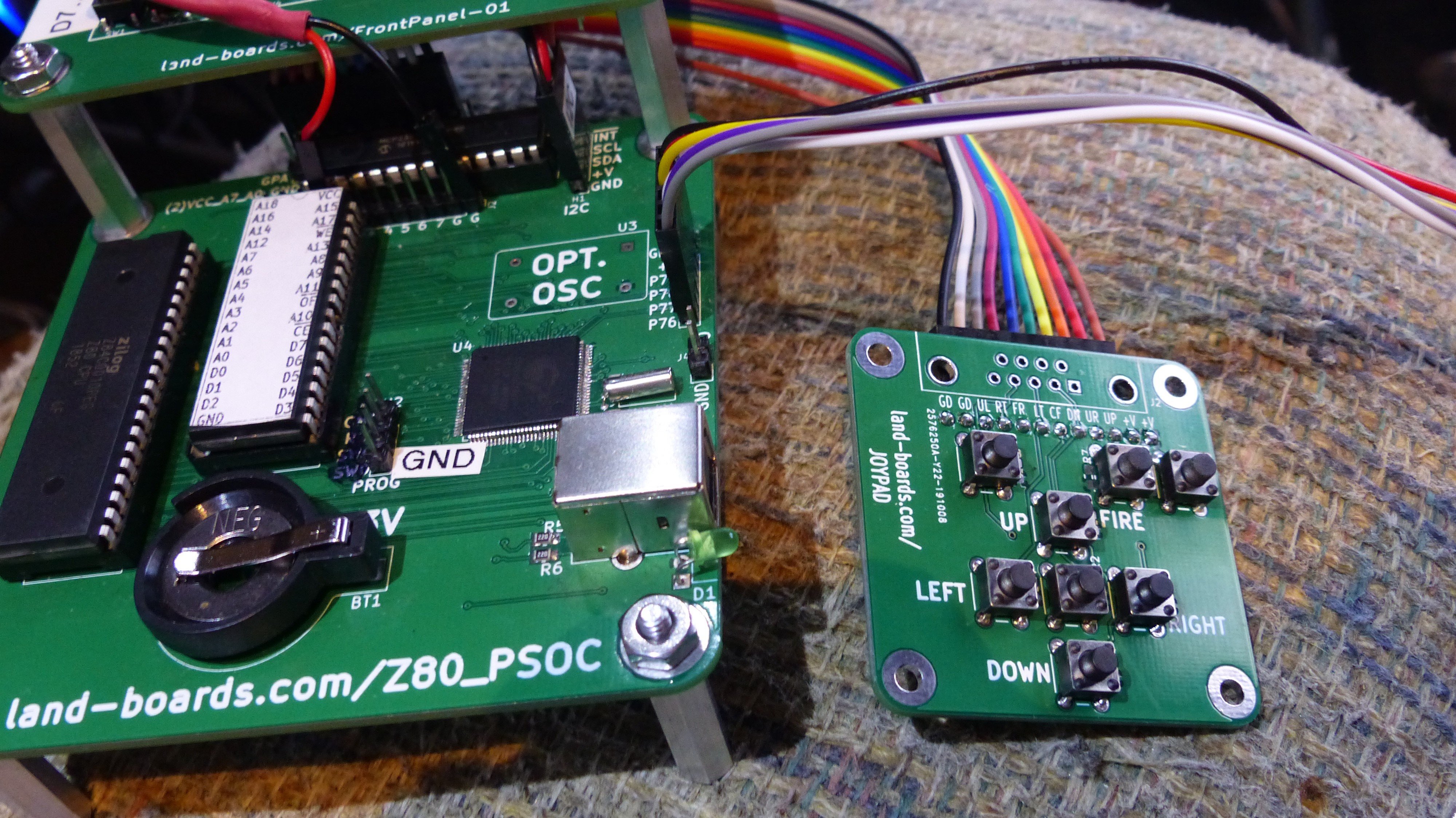
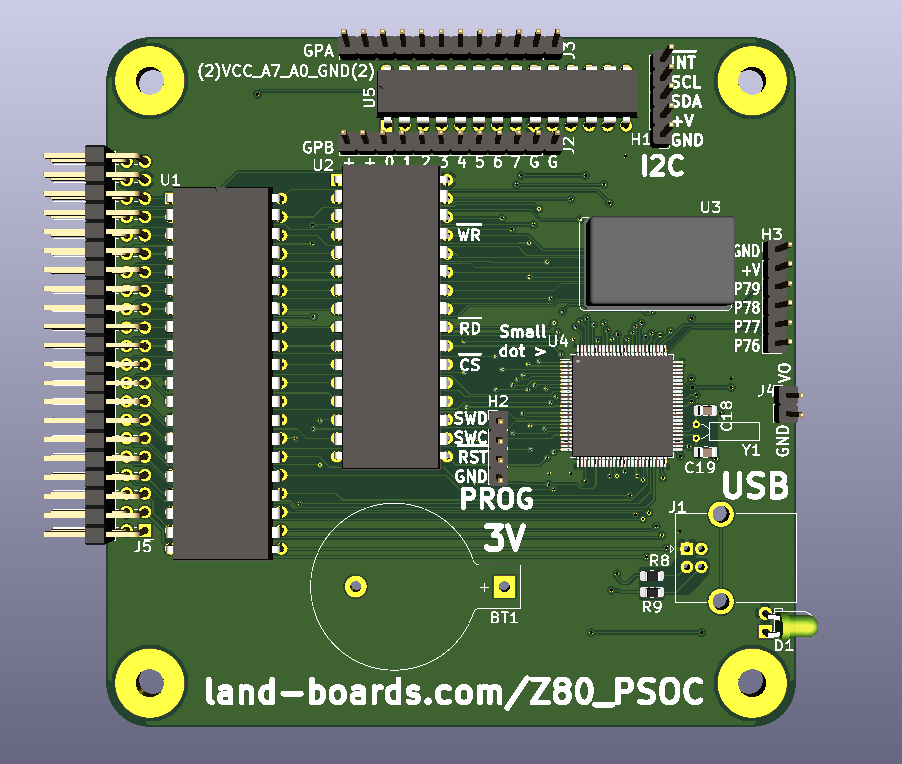
11/03/2019 at 18:46 • 0 commentsI spent a lot of time in the last log getting interrupts to work with the MCP23017 parts. The goal was to get my new JOYPAD to simulate keypresses to the Z80. I got interrupts working on the PSoC and learned a lot about interrupt on the PSoC along the way. But I forgot to put up a picture of the JOYPAD.
![]()
The JOYPAD has the usual direction buttons. It has a ribbon cable with all of the buttons brought out discretely as 8-bits. It also has a spot for a DB-9 if I want the JOYPAD to function as a classic Atari joystick. It has spots for pull-up resistor although I am using the MCP23017 pull-ups and didn't populate them on this board.
I needed this for a few different projects but wanted it especially for my R32V2020 RISC CPU design. I am working on a Tetris program and the pad will make it easier to interact with the program than a keyboard.
It also makes a nice addition to this project.
-
PIO Programming
11/03/2019 at 15:27 • 0 commentsThe RESET* line into the MCP23017 I2C Expansion IC is wired to the CPU reset so it can't be programmed if the Z80 isn't running. Moved the PIO initialization code to only be executed when the RUN button is pressed (since it takes the Z80 out of reset(.
Could take the Z80 out of reset by downloading loop forever code. At present, I am just running the BASIC_CP/M build since it lets me INP and OUT to I/O space.
After initializing the MCP23017 parts, the I2CINT* line is high. Pressing the RUN button on the Front Panel sets the I2CINT* line low.
PRINT INP(24) - Clears the interrupt left over from when the run button was pressed. The interrupt is still present since the key press is longer than the input MCP23017 processing time.
The MCP23017 is running as a PIO emulator. The Z80 IO addresses are:
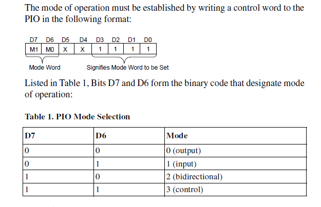
        #define PIOA_D              0x20    // decimal 32
        #define PIOA_C              0x22    // decimal 34
        #define PIOB_D              0x21    // decimal 33
        #define PIOB_C              0x23    // decimal 35
The PIO User manual shows the command interface. but it is somewhat modified since it is emulated by the PSoC. The PSoC has a state machine design which implements the setting of the port mode
OUT 34,79 - sets the PORT_A mode selection to Input. 79 dec is 0x4F.
OUT 35,79 does the same for PORT_B.
It looks like the input polarity register in the MCP23017 is pre-applied to the interrupt comparison default value.
The same applies to the JOYPAD. It pulls lines low so the input polarity is set to invert. The comparison value then, has to be set to 0.
After some tweeking the I2CINT* is only set by the last keypress on the front panel and can be cleared by reading INP(24). The Front Panel code could hang around until no keys are pressed and then clear the Interrupt Capture for the Front Panel.
But, this won't work as well for the keypad.
Interrupt Servicing
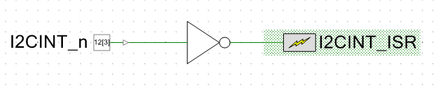
Added interrupt hardware to the schematic. Again pretty simple to add the hardware.
PSOC Creator made the interrupt handler file I2CINT_ISR.c which has the API templates and routines.
- I2CINT_ISR_Start( ) - starts up the ARM code for the Interrupt
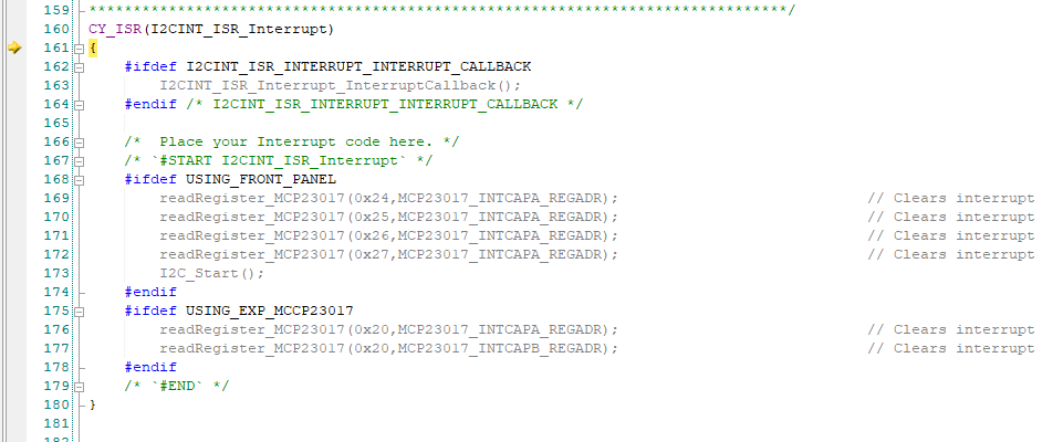
To start with the Interrupt Handler just clears the interrupt.
CY_ISR(I2CINT_ISR_Interrupt)
{
    #ifdef I2CINT_ISR_INTERRUPT_INTERRUPT_CALLBACK
        I2CINT_ISR_Interrupt_InterruptCallback();
    #endif /* I2CINT_ISR_INTERRUPT_INTERRUPT_CALLBACK */

    /*  Place your Interrupt code here. */
    /* `#START I2CINT_ISR_Interrupt` */
    #ifdef USING_FRONT_PANEL
          readRegister_MCP23017(0x24,MCP23017_INTCAPA_REGADR);                            // Clears interrupt
          readRegister_MCP23017(0x25,MCP23017_INTCAPA_REGADR);                            // Clears interrupt
          readRegister_MCP23017(0x26,MCP23017_INTCAPA_REGADR);                            // Clears interrupt
          readRegister_MCP23017(0x27,MCP23017_INTCAPA_REGADR);                            // Clears interrupt
        I2C_Start();
    #endif
    #ifdef USING_EXP_MCCP23017
          readRegister_MCP23017(0x20,MCP23017_INTCAPA_REGADR);                            // Clears interrupt
          readRegister_MCP23017(0x20,MCP23017_INTCAPB_REGADR);                            // Clears interrupt
    #endif
    /* `#END` */
}
The code is pretty dumb. It doesn't do anything other than the reads of the interrupt capture register which clears the interrupt. But it works and the interrupt line is no longer low. So, I no longer have to read INP(24) to clear the interrupt.
Hardware Changes in Rev 3 Card
Removing the RESET* line from the MCP23017 and pulling up the pin to Vcc. This will let the PSoC work with the MCP23017. This means an etch cut and add of a pull-up resistor on the Rev 1 board.
This change is actually mandatory since when the MCP23017 is held in reset it wants to drive the interrupt line and it bucks the MCP23017 chips on the Front Panel which are driving the interrupt line to the opposite state - not good.
PSoC Interrupt Change
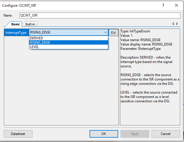
Working details - the PSoC allows 3 types of interrupts. Of the three, RISING_EDGE seems like the right one since it will only activate on the edge. Level could be better but I can't see where the level (high or low) gets set. It's probably for High, though.
Either way, this means I needed to change the schematic for the interrupt pin and interrupt function.
This lets the PSoC code detect the interrupt activation. The problem I found was this put me right back in the mode where I had to INP(24) to clear the interrupt line. And it isn't causing an interrupt anymore so that's better.
I did notice the interrupt going twice earlier. May be one for each edge of the input or could be a bouncy switch?
Switching to LEVEL fixed the problem of the interrupt getting missed. That's probably the right solution since it will keep calling the interrupt routine until it clears the interrupt completely.
The interrupt routine is getting called many times matching to the switch press duration. As soon as the routine exits the key is still pressed and the MCP23017 immediately goes at it again.
The card got stuck and here's why:
The grey sections show that the code is not included. When PSOC Creator built the code it remove the .h files that define these functions and the compiler, being smart took them out. I need to move the interrupt handler out of this file to prevent this in the future. PSOC Creator preserved the code in the area that they mark with comments and that is good so it wasn't lost but rewriting thee top of the auto-generated file removed the .h file that has the #defines for the function inclusion.
I am now back at the spot where the interrupt is being cleared which is good. Pressing a button on the Front Panel also causes and interrupt which gets eventually cleared. The Z80 code is being run (CP/M or MBASIC). There's once again no need to INP(24) to clear the interrupt.
That is all very good progress, but the JOYPAD still isn't working. Pressing buttons on the Front Panel works fine now so I could even use one of the buttons to reset the Z80 - a good goal in and of itself.
There must be some difference in the init code for the Front panel vs the Expansion MCP23017 parts.
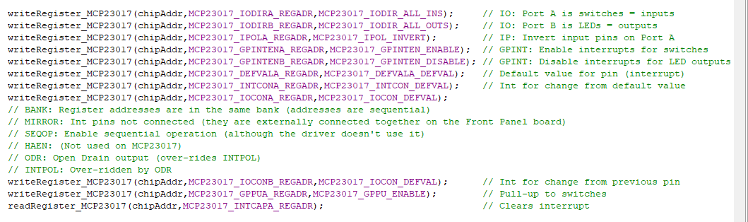
The Front Panel init code is:
That looks the same as the Expansion MCP initialization code. I wonder if the PIO commands need to be done from the Z80? Tried it and it didn't help.
I haven't checked this JOYPAD card out. Is it really working? Wow, rookie mistake! The connector on the cable is plugged in backwards at the Z80_PSOC end. Sometimes it pays to have a good sense of humor and just laugh at yourself.
Now pressing buttons on the JOYPAD does the same thing as pressing buttons on the Front Panel. They cause an interrupt to the PSoC just like they should.
Good spot to end this log. I'd like to have the pressing of the keypad cause a key value to be sent to the Z80 - just like a keyboard press. Right now, I think they would produce a lot of keys.
-
ZEXALL Instruction Set Test
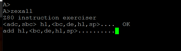
11/02/2019 at 13:43 • 0 commentsTrying to run the benchmark zexall Z80 Instruction Set Test. The program is hanging on accessing the SD card. The code is doing something I didn't expect. It's sending a command to the SD card that isn't 0x01 (wrote block) or 0x00 (read block).
It is sending a 0x2C command to the SD card interface. Not sure what that command is since the code I modeled the PSoC interface only used 0x00 and 0x01.Fixed the SD Card Hang
Running now. Put in code to ignore anything other than 0x00 and 0x01. Not a great solution but waiting to see if it passes the Instruction Set Test before tackling it.
Took quite a while at 10 MHz CPU Clock speed. Printing is messed up due to some of the formatting of the messages with greater than and less thans in the message.
A>zexall
Z80 instruction exerciser
 hl,....  OK
add hl,..........  OK
add ix,..........  OK
add iy,..........  OK
aluop a,nn....................  OK
aluop a,..  OK
aluop a,.....  OK
aluop a,(+1)...........  OK
bit n,(+1).............  OK
bit n,....  OK
cpd........................  OK
cpi........................  OK
.............  OK
 a...................  OK
 b...................  OK
 bc..................  OK
 c...................  OK
 d...................  OK
 de..................  OK
 e...................  OK
 h...................  OK
 hl..................  OK
 ix..................  OK
 iy..................  OK
 l...................  OK
 (hl)................  OK
 sp..................  OK
 (+1).........  OK
 ixh.................  OK
 ixl.................  OK
 iyh.................  OK
 iyl.................  OK
ld ,(nnnn).............  OK
ld hl,(nnnn)..................  OK
ld sp,(nnnn)..................  OK
ld ,(nnnn).............  OK
ld (nnnn),.............  OK
ld (nnnn),hl..................  OK
ld (nnnn),sp..................  OK
ld (nnnn),.............  OK
ld ,nnnn.........  OK
ld ,nnnn...............  OK
ld a,<(bc),(de)>..............  OK
ld ,nn....  OK
ld (+1),nn.............  OK
ld ,(+1)......  OK
ld ,(+1)..........  OK
ld a,(+1)..............  OK
ld ,nn.......  OK
ld ,........  OK
ld ,........  OK
ld a,(nnnn) / ld (nnnn),a.....  OK
ldd (1)....................  OK
ldd (2)....................  OK
ldi (1)....................  OK
ldi (2)....................  OK
neg...........................  OK
.....................  OK
...........  OK
shf/rot (+1)...........  OK
shf/rot ..  OK
 n,.....  OK
 n,(+1).......  OK
ld (+1),......  OK
ld (+1),..........  OK
ld (+1),a..............  OK
ld (),a................  OK
Tests complete
A>
Tests passed.
15 Mhz Hung
Tried 15 MHz (using the 10 MHz CPU) and it did not finish the first test. Not sure if this is a CPU problem or something to do with the peripheral emulation. The clock is a 50-50 duty cycle so it's probably not that.
12 MHz Passed
Running 12 MHz and it passed. That would be a 2-3 duty cycle clock so it surprises me that it passes.
-
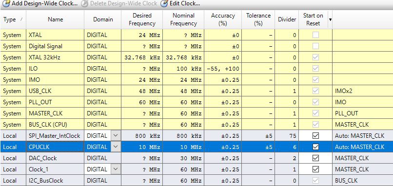
Changed CPU from 6 to 10 MHz
11/02/2019 at 10:33 • 0 commentsReplaced the 6 MHz Z80 with a 10 MHz Z80 part. This change is very simple in PSOC Creator. Just set the CPUCLK to 10 Mhz.
![]()
It works.
Tried overclocking at 12 MHz and it worked. Booted CP/M. Ran MBASIC.
Also tried 15 MHz and it also worked.
-
Grand Piano Demo Video
11/02/2019 at 10:29 • 0 comments -
Grand Piano Notes
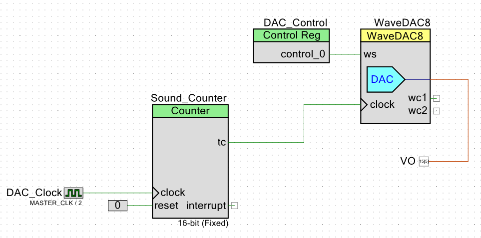
11/01/2019 at 23:34 • 0 commentsAdded a function to make the scale for a grand piano. Here's the logic in the FPGA.
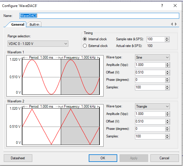
Here's the WaveDAC8 configuration:
This uses a note table to convert the note number to the frequency scaler.
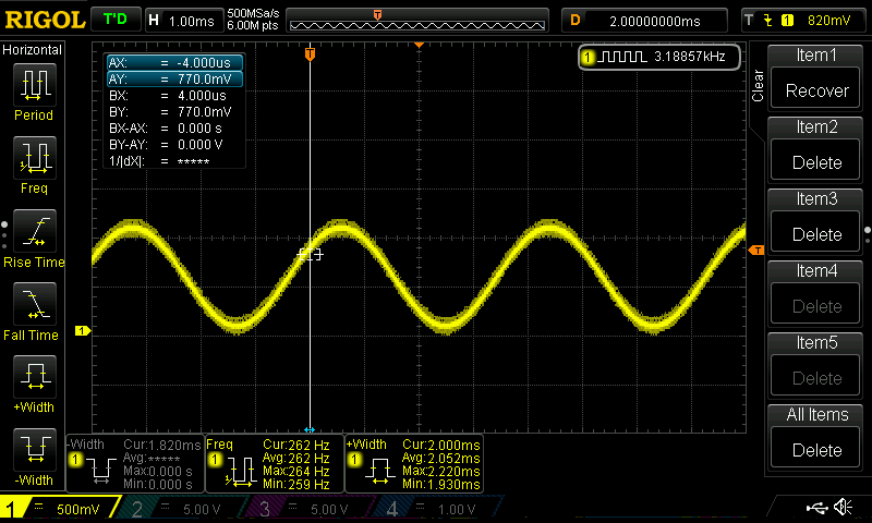
const uint16 notes[] = {12000, 10909, 10297, 9719, 9173, 8659, 8173, 7714, 7281, 6872,
    6487, 6123, 5779, 5455, 5148, 4859, 4587, 4329, 4086, 3857, 3640, 3436,
    3243, 3061, 2889, 2727, 2574, 2430, 2293, 2165, 2043, 1928, 1820, 1718,
    1622, 1531, 1445, 1364, 1287, 1215, 1147, 1082, 1022, 964, 910, 859,
    811, 765, 722, 682, 644, 607, 573, 541, 511, 482, 455, 430, 405, 383,
    361, 341, 322, 304, 287, 271, 255, 241, 228, 215, 203, 191, 181, 170,
    161, 152, 143, 135, 128, 121, 114, 107, 101, 96, 90, 85, 80, 76, 72,
    68, 64, 60, 57, 54, 51, 48, 45, 43, 40, 38};
Writing OUT 98,40 produces 262 Hz which is Middle C.
The output is a bit noisy. I used a 22 Ohm resistor instead of the chip inductor for the analog power so it's probably coupling in noise.
-
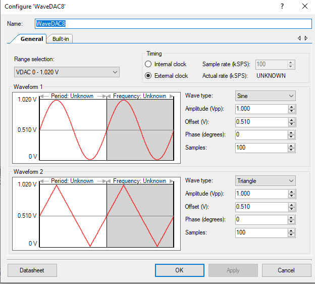
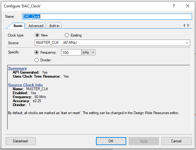
More DAC Output Design Details
11/01/2019 at 21:49 • 0 commentsThe Wave DAC in the PSoC doesn't allow the sin wave frequency to be set directly. The configuration screen for the WaveDAC8 lets you set:
This shows 200 samples, every 100 KHz. The scope shows a 1 KHz waveform which is correct.
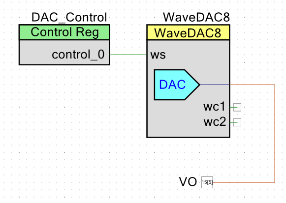
The two waveform selects are done with an internal hardware "pin". The API does allow several controls which the Z80 uses to control the DAC. I have taken the pin to ground so I'm only generating sine waves. It would be easy to add a control for sine/triangle waves. All it would take would be a register bit. Let's add that capability.
That works nicely.
The control/status register for the DAC is at 98 (dec) from the Z80. The data register is at 99 (dec) from the Z80.
Control register values are:
- 00 - Stop the Wave generator
- 01 - Start the Wave generator
- 03 - Set the amplitude to 1.024V
- 04 - Set the amplitude to 4.096V
- 05 - Set the DAC_Control to Sine Wave
- 06 - Set the DAC_Control to Triangle Wave
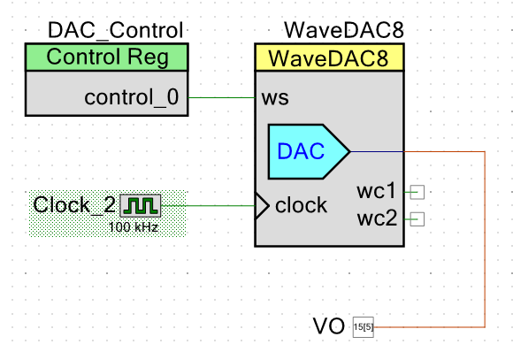
Changing the sample frequency can be done via an external pin. Replacing the 100 KHz internal clock with an external 100 KHz clock does exactly the same thing as above.
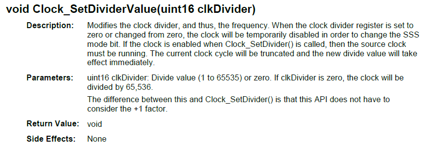
The Clock_2 above has an API which can allow the PSoC to set some values. Unfortunately, there's no way to set the clock for an arbitrary frequency which would be nice for tone generation. There is an API for:
This would not be a great choice since it lacks the sort of resolution to code a grand piano keyboard but it's a good place to play around with the idea. Changed the number of samples to 16 which is a bit blocky but should be fine for this test. Left the clock at 100 KHz. Added a call to the function when the Z80 writes to the DAC data port.
Results are:
OUT 98,X Frequency 0 68 Hz 1 14.6 KHz 2 7.3 KHz 3 4.9 KHz 4 3.6 KHz 254 67 Hz 255 68 Hz The top frequency should be 100 KHz divided by 16 or 6.25 KHz. The difference could be accounted for due the the extension of the 8-bit value from the CPU to the 16-bit counter value. Could probably figure it out mathematically, but it's pretty easy to just OUT values and see what I get. Middle C is 261.6 Hz. OUT 98,62 gets pretty close.
A table of notes to frequency values could give additional precision. I'm taking the 8-bit frequency value and shifting it into the 16-bit value to load the register. Should be able to get some precision doing that. I did something similar for my R32V2020 32-Bit RISC CPU design. The PSoC can easily do a lookup into a 256 entry table of 16-bit values.
With a bottom frequency of 68 Hz, that's a pretty good range. 57 hZ is the bottom end (when setting the divisor to 0xFFFE. The other end is well above the audio range I care about (14.6 KHz).
Also, if we set the clock to the precise clock we can get 0.25% accuracy. Not that my tone deaf ear can tell the difference.
I spent a couple of hours working on a 24-bit counter to pre-scale the 60 MHz PSoC CPU clock but am having trouble getting it to count.
-
Real Time Clock (RTC) Error - Fixed
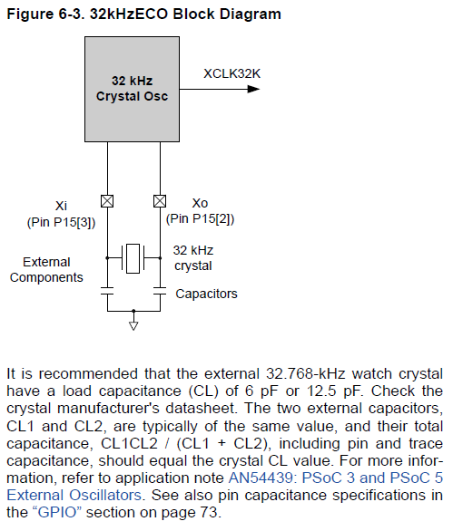
11/01/2019 at 14:01 • 0 commentsThe RTC is running too fast. Weird. There's not much to it. I wonder if the loading caps are the wrong values?
Debugging the RTC clock via taking over the DAC output pin and sending out the 32.768 KHz clock.
Running frequency is 190.912 KHz. That is 5X the 32.768 KHz crystal.
Touching the crystal shifts the frequency to 32.768 KHz temporarily.
The crystal is an Abracon part, PN: AB38T-32.768KHZ.
Load Capacitance: 12.5 pF
I do have two load capacitors. I wonder if they are correct? The PSoC datasheet has:
Right now I have 8 pF caps so I definitely have too much load capacitance. Not sure what the trace capacitance is. I did remove the ground fill below the crystal so it would be less. This note is easier since they do the math.
Looks like I need to change to 18 pF caps.
Clock works
Replaced the caps with 18 pF parts and the frequency is now stable AT 32.7 Khz. Can't measure the accuracy too closely with the scope frequency counter but it says 32.7797 Khz which is reasonably close to the 32.768 Khz value. It is 0.03% accurate (I doubt the scope is that accurate). Perhaps the difference is between the 18 pF parts I used and the 19 pF from the calculation above.
The BASIC code to set and read the timer is documented here.
-
Rev 3 Board?
11/01/2019 at 11:33 • 0 commentsAdded a 40 pin bus expansion connector for a Rev 3 board.
![]()
Adds all of the Z80 lines minus HALT* and RFSH*. Has 2 power and 2 ground connections.
Bought Rev 2 boards but I think I should skip them and order rev 3 with the expansion connector.
This would require that the WAIT* signal be set to open collector with pull-up from the PSoC for accesses to the expansion connector.
Considering making a TMS9918A Graphics with PS/2 keyboard expansion card. Then this could be a stand-alone unit.
The 40-pin connector could be vertical or horizontal.
3-Chip Z80 Design
Combining a Z80 retro design with a modern PSoC CPU.