land-boards.com
-
Front Panel LEDs/Switches I/O Mapped
10/14/2019 at 23:39 • 0 commentsMapped the front panel to I/O addresses 24-27 (dec). The NASCOM basic uses INP to read I/O ports and OUT to write I/O ports.
Writing to address 24 (dec) writes to the bottom LEDs. Writing to address 27 (dec) writes to the top row of LEDs.
Reading address 24 (dec) reads the bottom switches. Reading address 27 (dec) reads the top row of LEDs.
Of course, the other two sets of 8 LEDs and switches are at 25 (dec) and 26 (dec).
-
Front Panel LEDs/Switches I/O Mapped
10/14/2019 at 23:32 • 0 commentsMapped the front panel to I/O addresses 24-27 (dec). The NASCOM basic uses INP to read I/O ports and OUT to write I/O ports.
Writing to address 24 (dec) writes to the bottom LEDs. Writing to address 27 (dec) writes to the top row of LEDs.
Reading address 24 (dec) reads the bottom switches. Reading address 27 (dec) reads the top row of LEDs.
Of course, the other two sets of 8 LEDs and switches are at 25 (dec) and 26 (dec).
-
Receiver Overruns (as expected)
10/14/2019 at 17:31 • 0 commentsThe USB to Serial into the card is much faster than the Z80 can handle. If you are typing keys on the keyboard things are fine. But if you want to upload code to the card then things go bad quickly since the Z80 can't keep up. In the real thing that is handled by toggling the RTS line back to the host. In the case of this emulation of the Serial interface there is no RTS line to toggle.
There isn't an equivalent problem for serial output since the Z80 waits on the Transmit Empty before sending another character. Send packets of one byte on USB isn't particularly efficient but it works just fine in practice. The USB-Serial connection to the PC is very fast and any bytes just get put into single byte packets and sent out the USB to the Host. I will check the speed of the interface later to see how efficient this is and whether improvements should be made or left as-is.
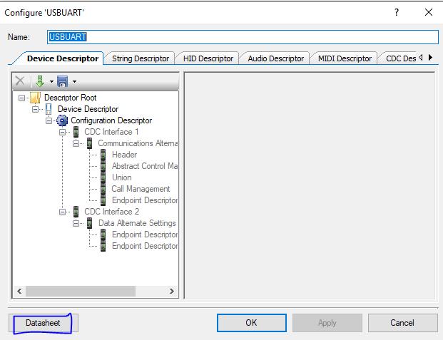
The PSoC interface to the USB is called USBUART in their documentation. Double clicking on the UART in the GUI pulls up this screen.
Clicking on the Datasheet button in the bottom left pulls up the USBUART datasheet.
There are a few PSoC functions which are used when receiving data from the USB interface. In the USBUART example the code uses the following functions:
- USBUART_IsConfigurationChanged()
- USBUART_GetConfiguration()
- USBUART_DataIsReady()
- USBUART_GetAll(buffer)
It should be possible to use these functions to determine if the packet size is greater than 1 and then get one byte at a time to feed to the SIO interface. If the packet size is 1 and there's room for data then it can be sent to the SIO interface.
To determine if there's room for another character in the SIO interface look at the SIO Status Register 0 for Port A. The relevant bit is the D0 bit which 1 if there's still a character in the receive buffer.
The SIO routine is:
- sendCharToZ80()
It's easy to see that there's a difference between a routine which sends one character to the Z80 and routines which receive a packet of up to 64-bytes.
Let's make the assumption that if the GetAll routine isn't called the PSoC and/or USB interface waits on the data to be read before accepting further USB packets. That has to be the case otherwise there'd always be overruns.
Further, GetAll(buffer) is called with a pointer to a buffer and it returns the byte count from that call. To deal with this difference, the byte count could be decremented every time a character is send to the Z80. The USB receive function would be inhibited until the count has reached zero.
This is a fairly simple change to the current code. In main( ):
if (0u != USBUART_DataIsReady())
...
Change to:
/* Check for input data from host. */
/* Only do the check if the buffer is already empty */
if ((0u != USBUART_DataIsReady()) & (USB_To_Z80_RxBytes_count == 0))
Then, read the buffer and check if it's a single character and the SIO receiver buffer is not busy.
USB_To_Z80_RxBytes_count = USBUART_GetAll(buffer);
if ((USB_To_Z80_RxBytes_count == 1) & (checkSIOReceiverBusy() == 0))     // Input 1 character immediately
{
     sendCharToZ80(buffer[0]);
     USB_To_Z80_RxBytes_count = 0;
}
Add the function checkSIOReceiverBusy( ) to Z80_SIO_Emul.c as:
///////////////////////////////////////////////////////////////////////////////
// uint8 checkSIOReceiverBusy(void) - Check the SIO port A receiver status
// Returns:
//  0 if the port can take another character
//  1 if the port is busy and can't take another character

uint8 checkSIOReceiverBusy(void)
{
    return (SIO_A_RD0 & SIOA_CHAR_RDY);
}
Back in main( ), add in this code to the main loop:
        if (USB_To_Z80_RxBytes_count > 0)           // There are chars in the input buffer (USB -> Z80)
        {
            if (checkSIOReceiverBusy() == 0)        // Check if receive buffer can take another character
            {
                sendCharToZ80(buffer[bufferOff]);   // Send received character to Z80 SIO interface
                bufferOff++;                        // ready for next character
                USB_To_Z80_RxBytes_count--;         // worked off one character
                if (USB_To_Z80_RxBytes_count == 0)  // Sent last character to Z80
                {
                    bufferOff = 0;                  // point back to start of character in buffer
                }
            }
        }
Those changes made it a lot better but not yet perfect. If I sent in smallish packets it works. If I sent in large packets it goes bad. Might have something to do with end points? There's something odd noted about packets that are 64 bytes. Will need to investigate because that's about where the problem happens.
-
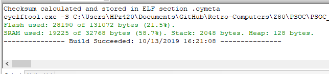
PSoC Utilization
10/13/2019 at 20:27 • 0 commentsThe PSoC compile shows:
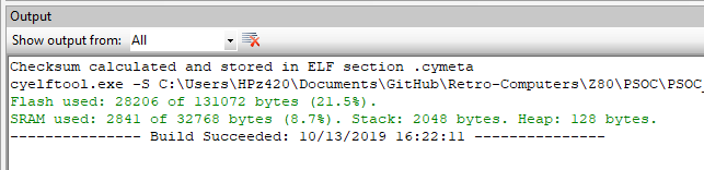
The SRAM is more than half used. This is because the C compiler thinks that the ROM monitor that is downloaded to the Z80 is an array that can be changed. To keep the ROM monitor in EPROM and not copy it to RAM, use the keyword const:
const unsigned char monitor_eprom[] =
{
0xF3, 0xC3, 0x8A, 0x01, 0x00, 0x00, 0x00, 0x00, 0xC3, 0x24, 0x01, 0x00,
0x00, 0x00, 0x00, 0x00, 0xC3, 0xC0, 0x00, 0x00, 0x00, 0x00, 0x00, 0x00,
...
After that change, the resources are:
That frees up 16K of SRAM (half the internal SRAM of the PSoC) and only cost 16 more bytes of ROM.
There is still a lot of free space in the PSoC for additional logic.
------------------------------------------------------------ Technology mapping summary ------------------------------------------------------------ Resource Type : Used : Free : Max : % Used ============================================================ Digital Clocks : 3 : 5 : 8 : 37.50 % Analog Clocks : 0 : 4 : 4 : 0.00 % CapSense Buffers : 0 : 2 : 2 : 0.00 % Interrupts : 9 : 23 : 32 : 28.13 % IO : 65 : 7 : 72 : 90.28 % Segment LCD : 0 : 1 : 1 : 0.00 % I2C : 1 : 0 : 1 : 100.00 % USB : 1 : 0 : 1 : 100.00 % DMA Channels : 0 : 24 : 24 : 0.00 % Timer : 0 : 4 : 4 : 0.00 % UDB : : : : Macrocells : 32 : 160 : 192 : 16.67 % Unique P-terms : 52 : 332 : 384 : 13.54 % Total P-terms : 53 : : : Datapath Cells : 0 : 24 : 24 : 0.00 % Status Cells : 4 : 20 : 24 : 16.67 % Status Registers : 3 : : : Sync Cells (x2) : 1 : : : Control Cells : 9 : 15 : 24 : 37.50 % Control Registers : 9 : : : Comparator : 0 : 2 : 2 : 0.00 % Delta-Sigma ADC : 0 : 1 : 1 : 0.00 % LPF : 0 : 2 : 2 : 0.00 % SAR ADC : 0 : 1 : 1 : 0.00 % DAC : : : : VIDAC : 1 : 0 : 1 : 100.00 % -
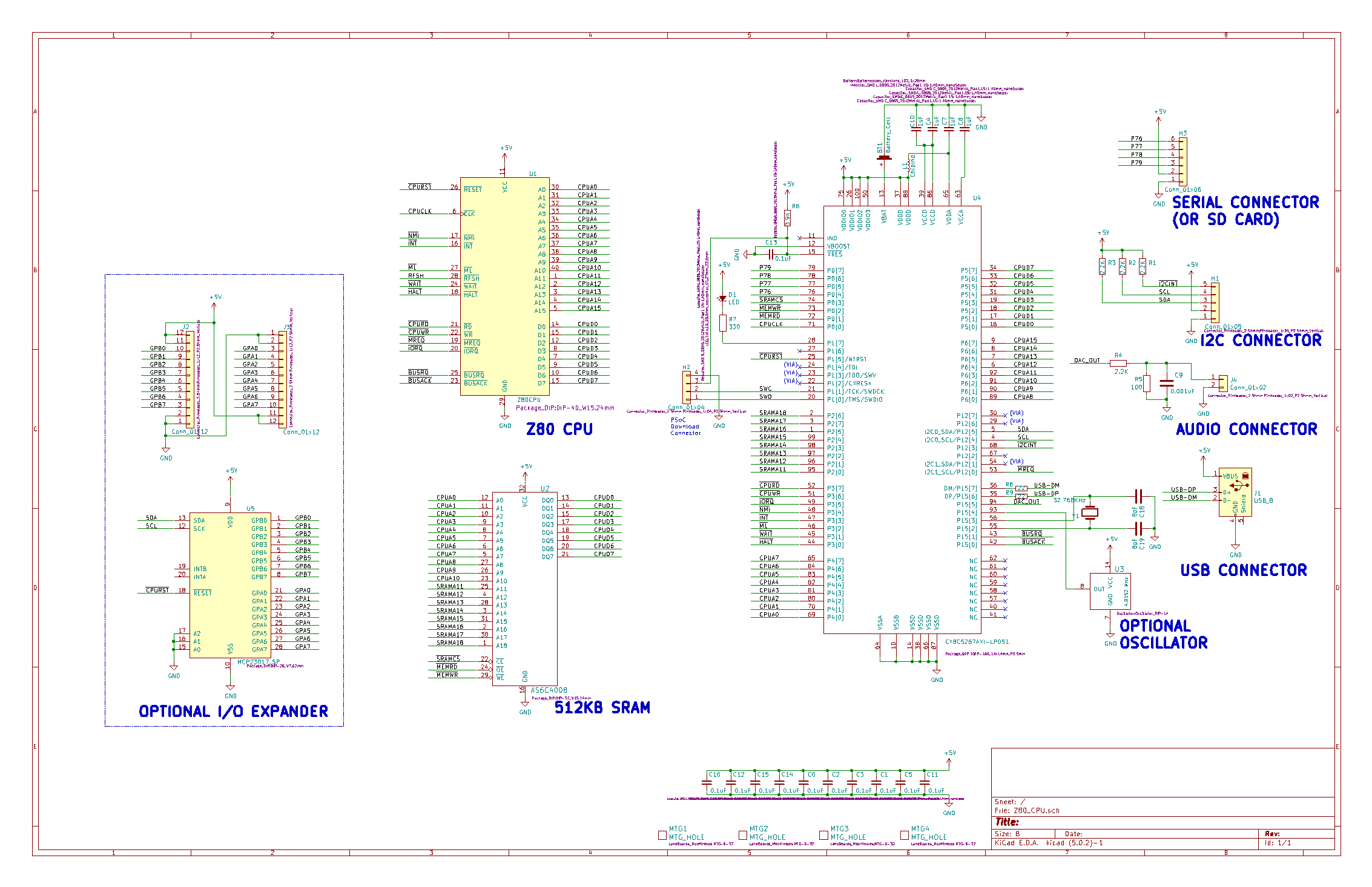
Schematic - Rev 1
10/13/2019 at 14:13 • 0 commentsHere's the current schematic.
![]()
-
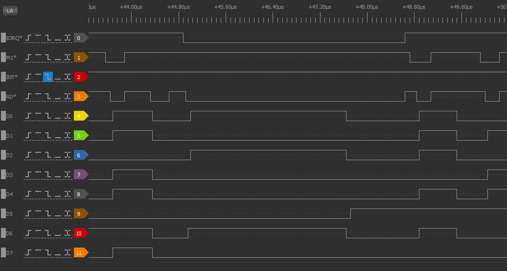
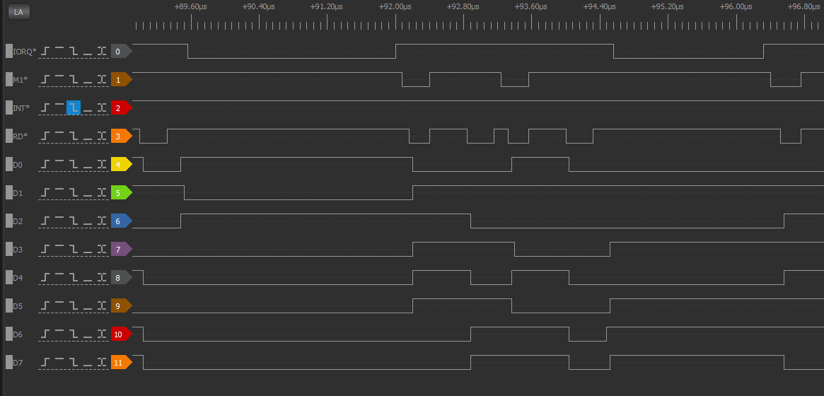
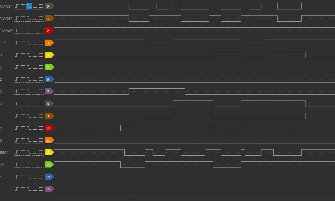
SIO Emulation - I/O Timing
10/13/2019 at 14:09 • 0 commentsThe majority of the time the Z80 is reading/writing SRAM. The SRAM is a 55 nS part and runs with no wait states. I/O is slowed down by reality (serial data rates are much slower than CPU times). However, it is interesting to see what differences there might be between emulated I/O and I/O performed by dedicated chips.
I/O Timing is somewhat variable since the I/O (currently) is done by the PSoC polling the IO interface to see if WAIT* is active. Here's one typical read cycle time of about 3.8 uS.
![]()
SIO control register reads consist of a write to the register number followed by a read from the selected SIO register. The time for both accesses is 6.8 uS.
![]()
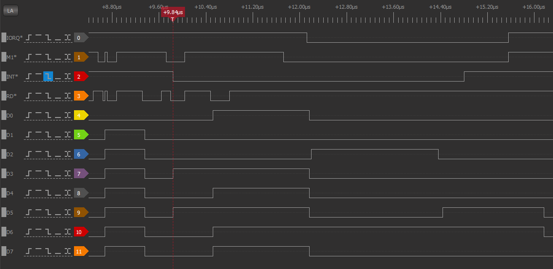
Interrupt Timing
The time from when an interrupt is created to when the interrupt is removed is about 5 uS.
![]()
I am using PSoC calls to functions that read/write registers. The inefficiency of the calls could be lessened by in access to the registers without calls. by When I tried putting the code in line I had trouble but it might be possible to figure out why. But it's possible that there were other things wrong with the code when I tried it
Writes to control registers could be posted and WAIT* removed more quickly. If the software is running a polling loop waiting on, say, transmit ready, it really doesn't matter much since the next serial write is waiting on the last character to be sent anyway.
Adding input and output software buffers and driving the interfaces with interrupts could also make the code faster. But, in the end it's just talking to slow serial interfaces.
-
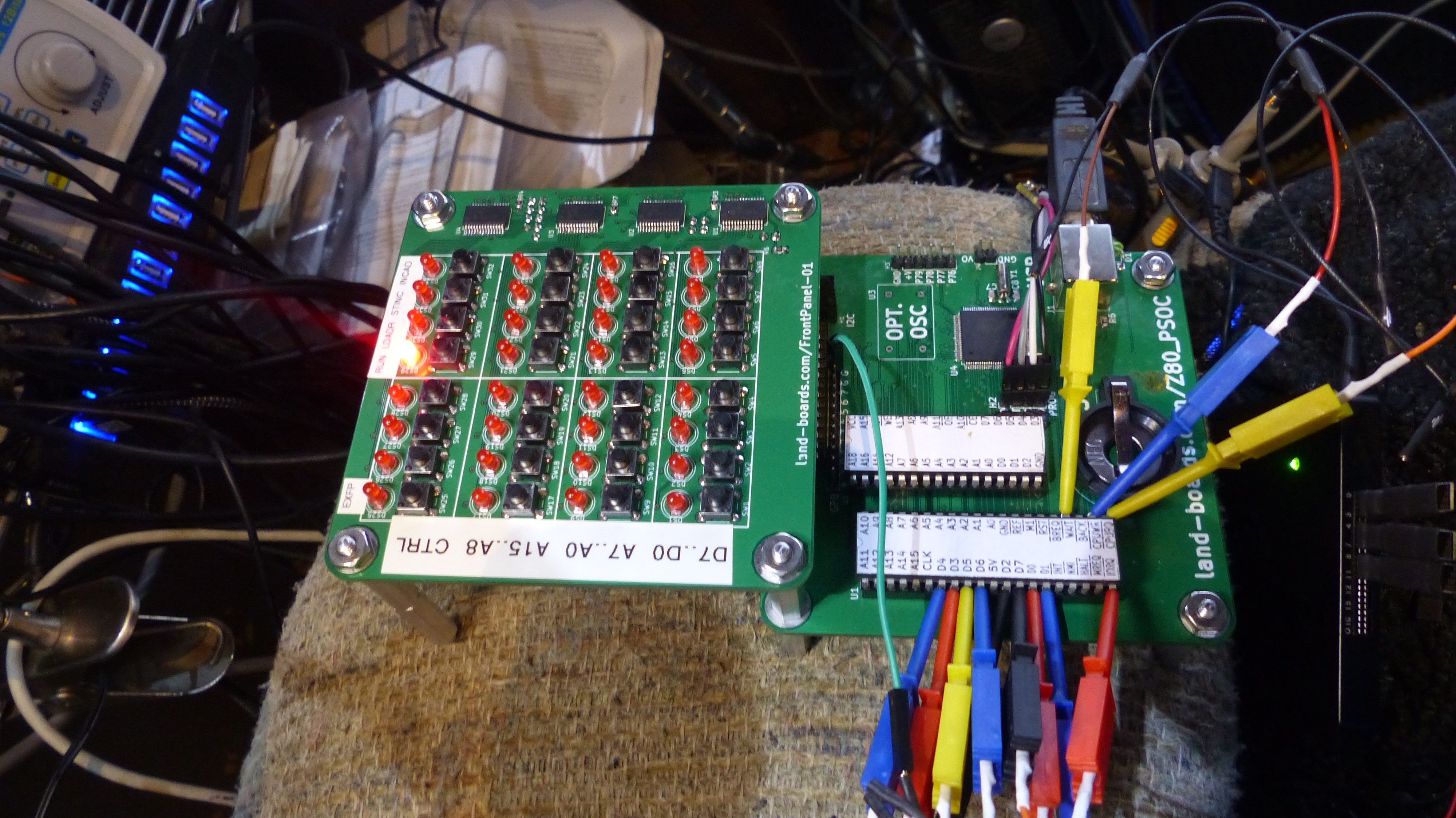
Debugging Techniques
10/13/2019 at 13:49 • 0 commentsOne beauty of using the PSoC to emulate peripherals is that it can single-step through IO code. I used that a lot in debugging the SIO emulator. Plus, having a CMOS processor let me stall the processor as the PSoC single stepped. Grabbing the Z80 lines with my DSLogic+ Logic Analyzer makes this easy.
![]()
The PSoC in-circuit debugger allow breakpoints to be set and code single stepped.
The logic analyzer can show the static value of lines as well as trigger on levels or edges.
-
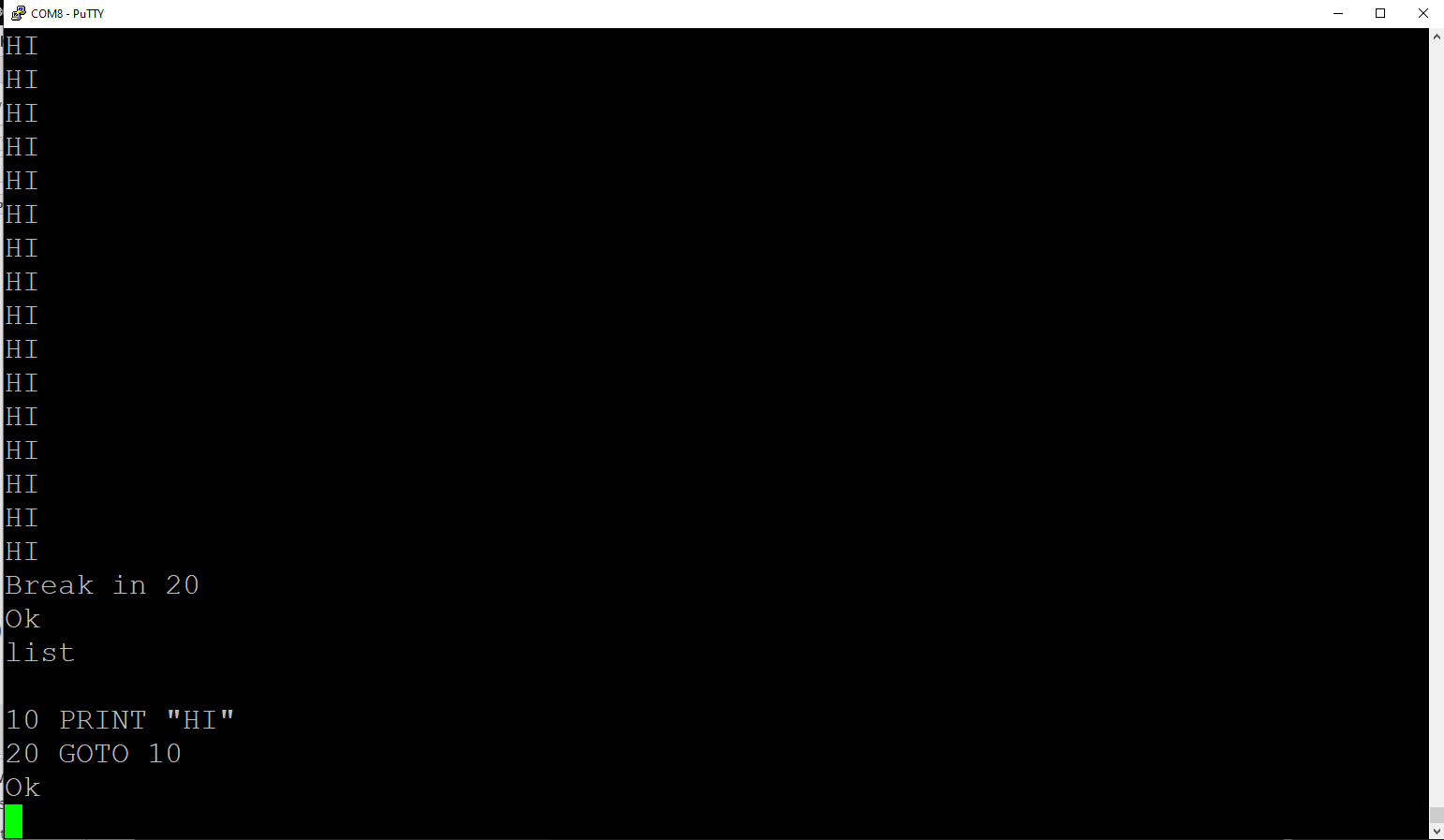
BASIC Running
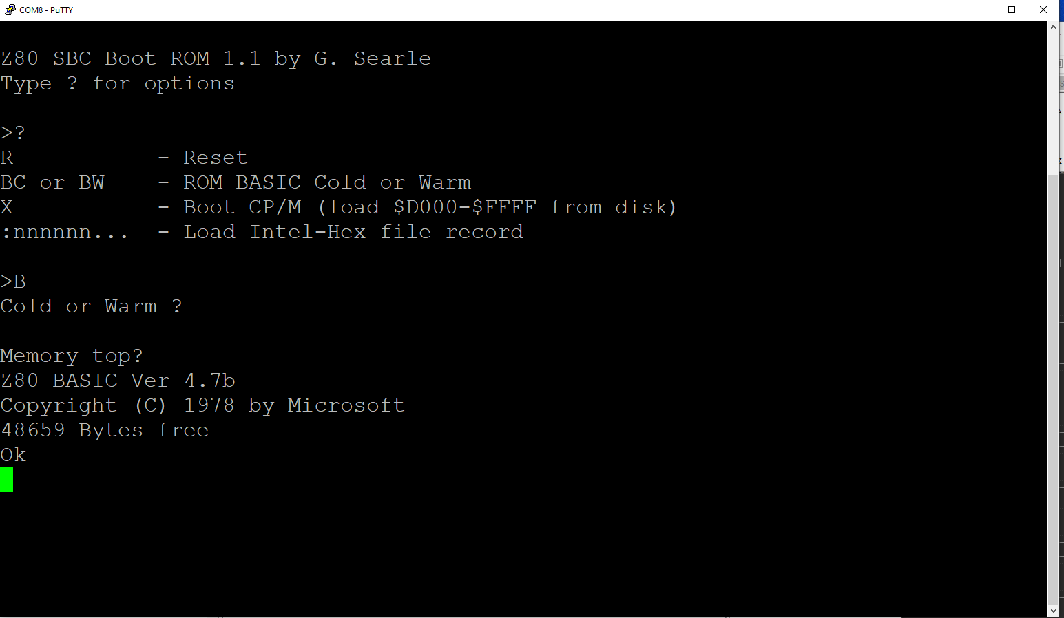
10/13/2019 at 13:31 • 0 commentsI got the Serial input interrupt working. So the SIO emulation is working for both transmit and receive.
I was rewarded with Grant's prompt.
![]()
BASIC came right up.
![]()
Working!!!
![]()
Archived working PSoC code here (002 file)
-
SIO Emulation - Serial Out working (Part 4)
10/13/2019 at 00:03 • 0 commentsThe PSoC is now operating with the USB-Serial sending out data to the USB when the Z80 writes to the SIO.
I was rewarded with Grant's prompt.
![]()
Used the DSLogic Plus logic analyzer a lot to make it work. Here's the setup.
![]()
I am monitoring IORQ*, Data Lines, RD*, WR* and WAIT*.
Ended up with PSoC code that captures all SIO control register writes even though many of them will not be used. Some of them are interrelated, particularly in interrupt handling.
Next, make Serial input work. A tad more complicated because I now have to emulate interrupts from SIO.
-
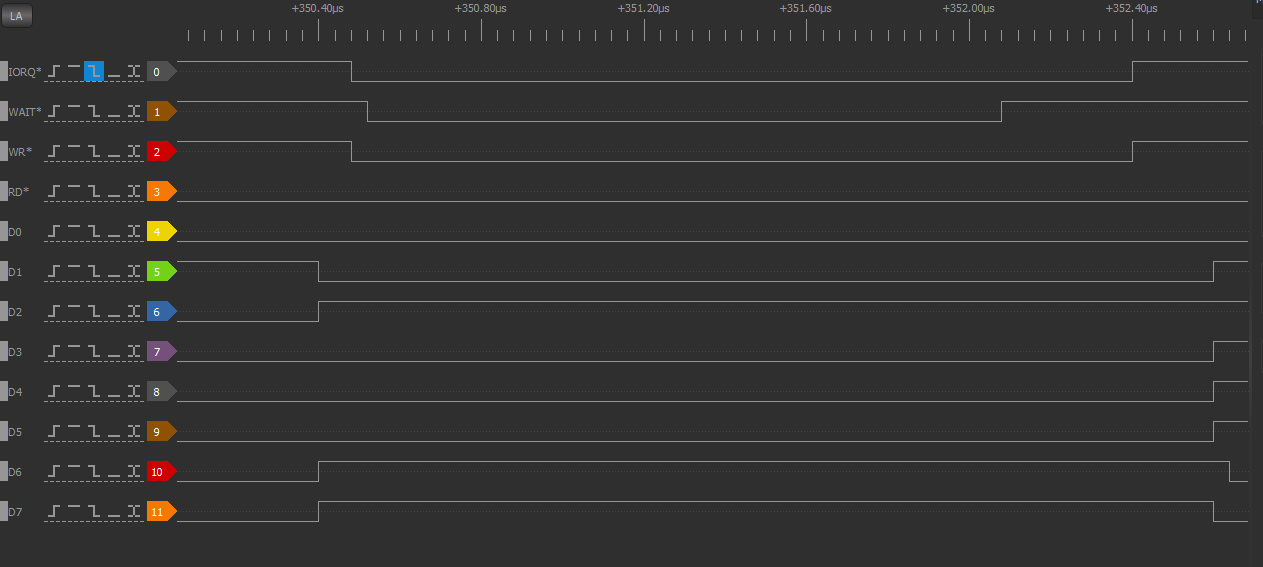
SIO Emulation - Debugging (3)
10/12/2019 at 18:59 • 0 commentsIt is really, really easy to debug the I/O emulator using the PSoC debugger. I can single step through the code. With the DSLogic+ Logic analyzer I can even see the I/O instructions being sent from the Z80 one at a time. Here's one of the CPU cycles.
This corresponds to the code:
0408   01AE 3E 04       		LD	A,$04
0409   01B0 D3 02       		OUT	(SIOA_C),A
I've split up the code into Z80_IO_Handle.c and Z80_SIO_emul.c code. The Z80_IO_Handle file looks at the address of the IO and calls the appropriate code in Z80_SIO_emul file. This lets the emul code handle the pair of writes to the control register(s).
Got the I/O writes to SIO working. Here's the timing of writing the SIO_A registers:
Here is one IORQ* cycle zoomed in:
This is 2uS wide IORQ*.
3-Chip Z80 Design
Combining a Z80 retro design with a modern PSoC CPU.