Supercell
-
Notes on Fingers with Elastic Cord vs Springs/Similar
09/07/2020 at 21:26 • 0 commentsThis project log will go into more detail on the decision between elastic cords vs springs/similar from the previous project log on return mechanisms. When I mean similar, I mean the effective end result in term of how the return force is distributed on each individual joint.
The discusion will mainly concern underactuated designs where the finger joints don't follow a fixed predictable path, and can vary depending on things like obstructions or resistance in the joints. Typically, an example of an underactuated finger would be ones that commonly use a single actuation cord to control multiple joints in the finger like the e-NABLE Raptor design. Underactuated designs allow for fingers to conform better to objects because of variable angle of each joints, but at the cost of unpredictability in the system where you can not fully predict what angle the fingers may end up.
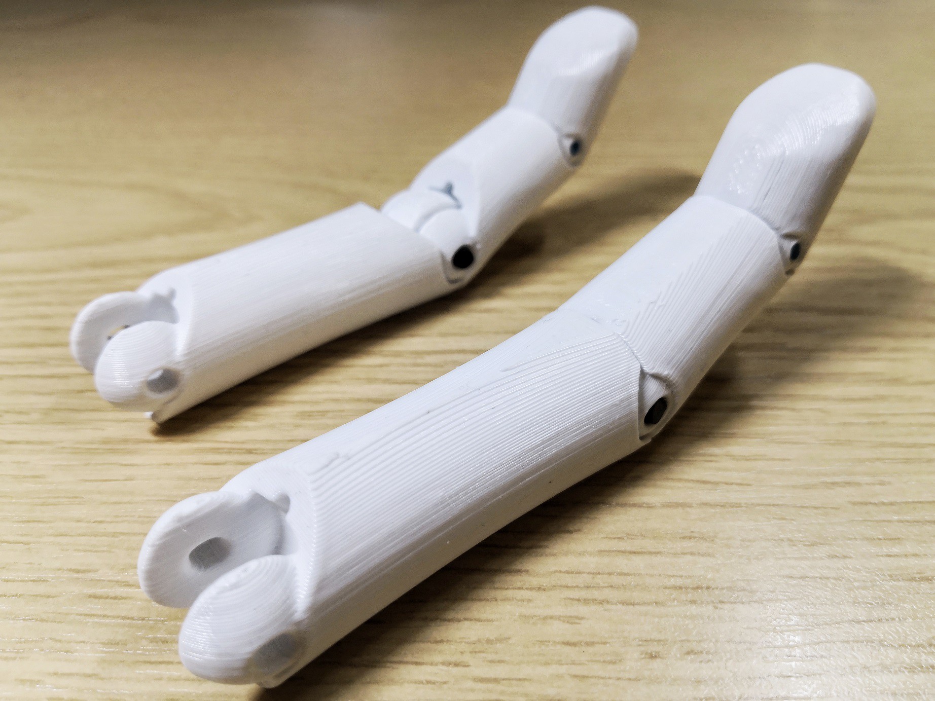
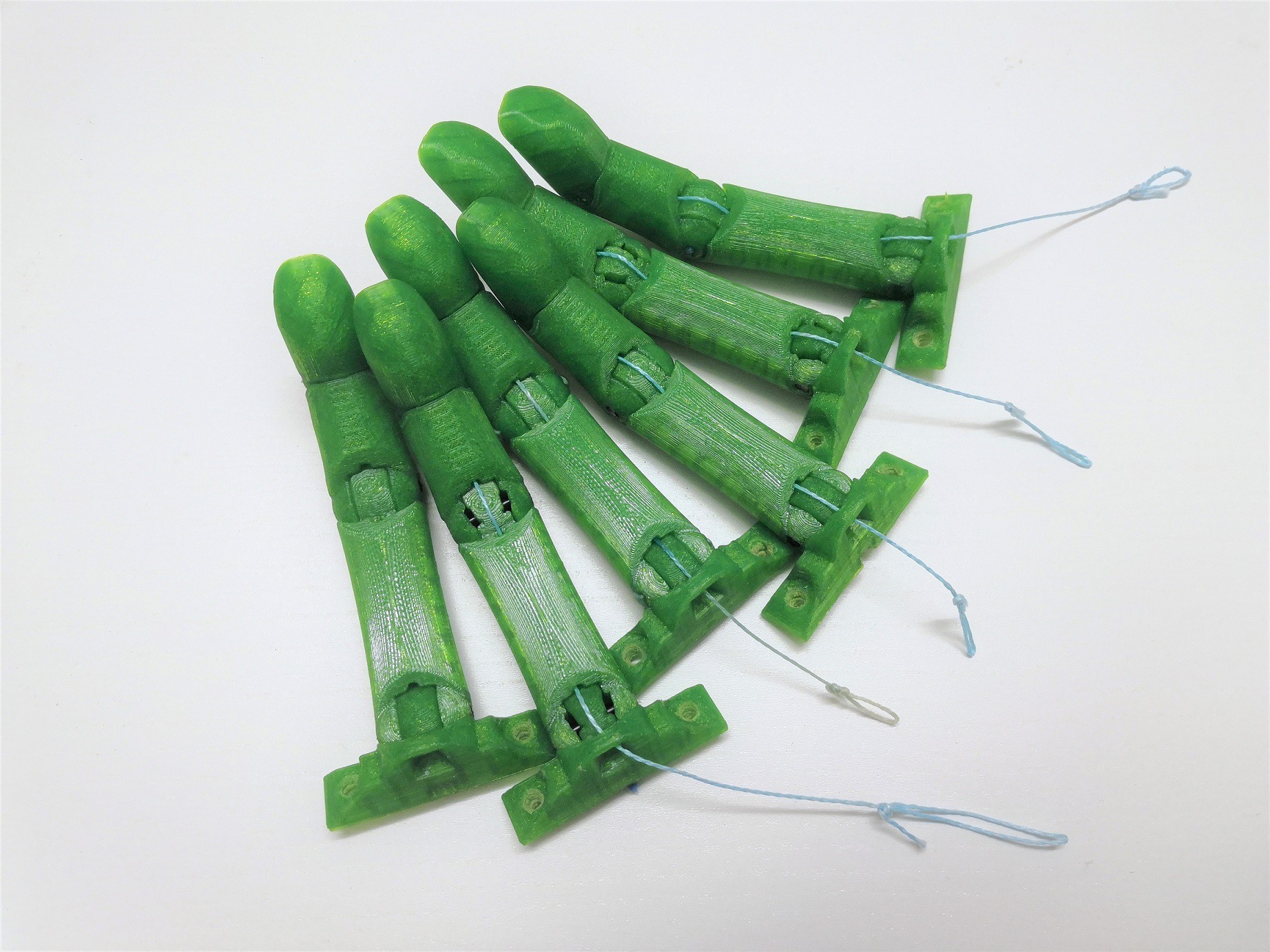
In the examples for describing the effect of the fingers, I'll be using a two joint example. The fingers shown in the pictures won't be two jointed so just ignore the extra joint at the finger tip. Also assume that the thumb is fixed and non-moving. Hand shown is the MK0PF variant for easy posing.
Spring/Similar Fingers
For a spring/similar design, there will be one per joint with a given torque required to close each spring. For the torque required at each joint with springs, they will always remain independent of one another and will always be constant for a given angle. For an underactuated finger with two joints, the single actuation cord will transmit its force onto whichever joint that has the least resistance. So for a spring design with equal torque required to close each joint, the angles at each joint will close equally as they have to balance each other out. Therefore assuming no external forces on the fingers, you can predict that the angle of the knuckle joint will be equal to the finger joint.
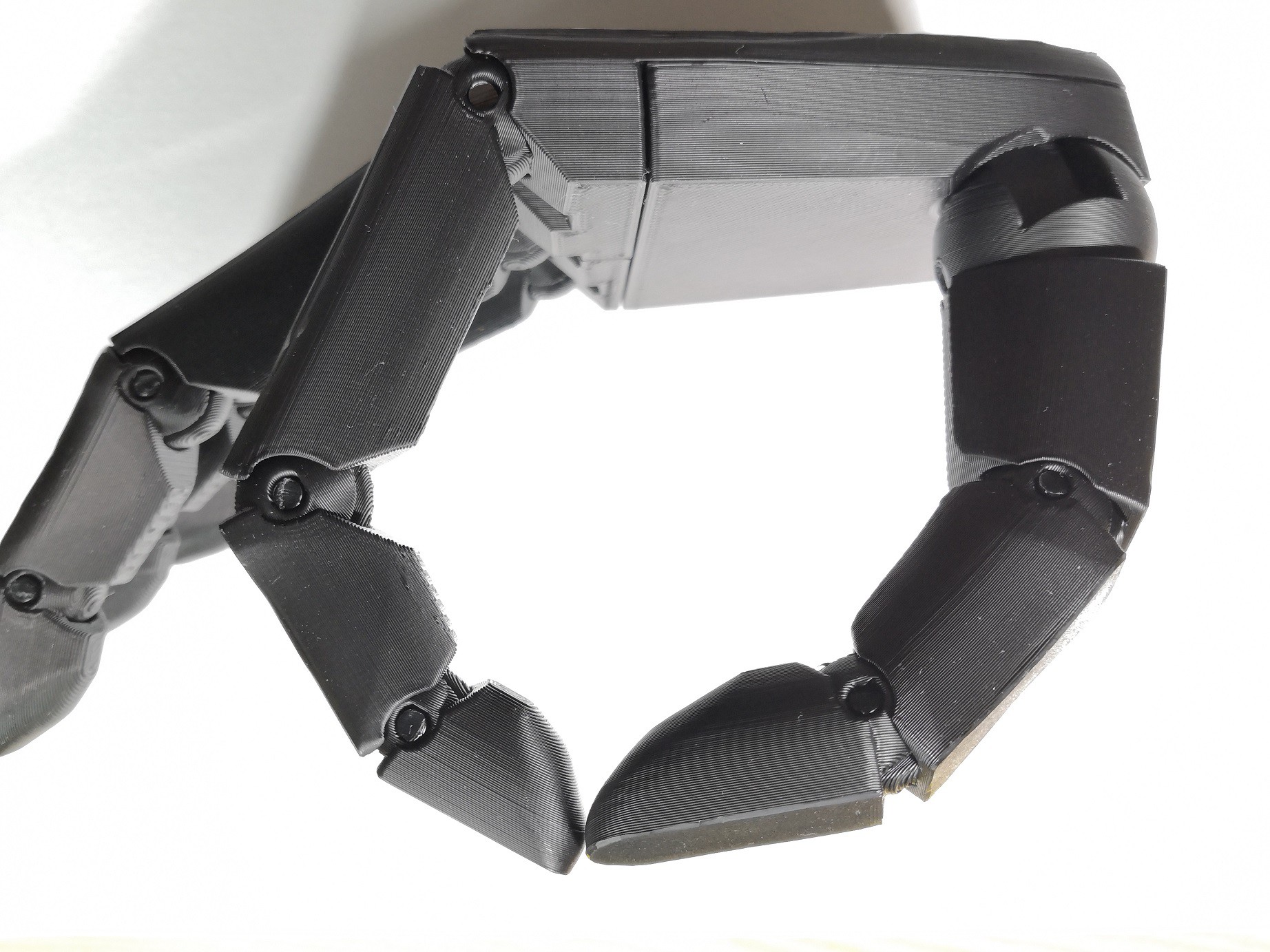
It may seem reasonable that from above with the spring design, you can predict what angle the fingers can end up to be but this is assuming no external factors. If introducing external factors, an example use case would be when doing a pinch/tripod grip for picking items up as shown bellow.
![]()
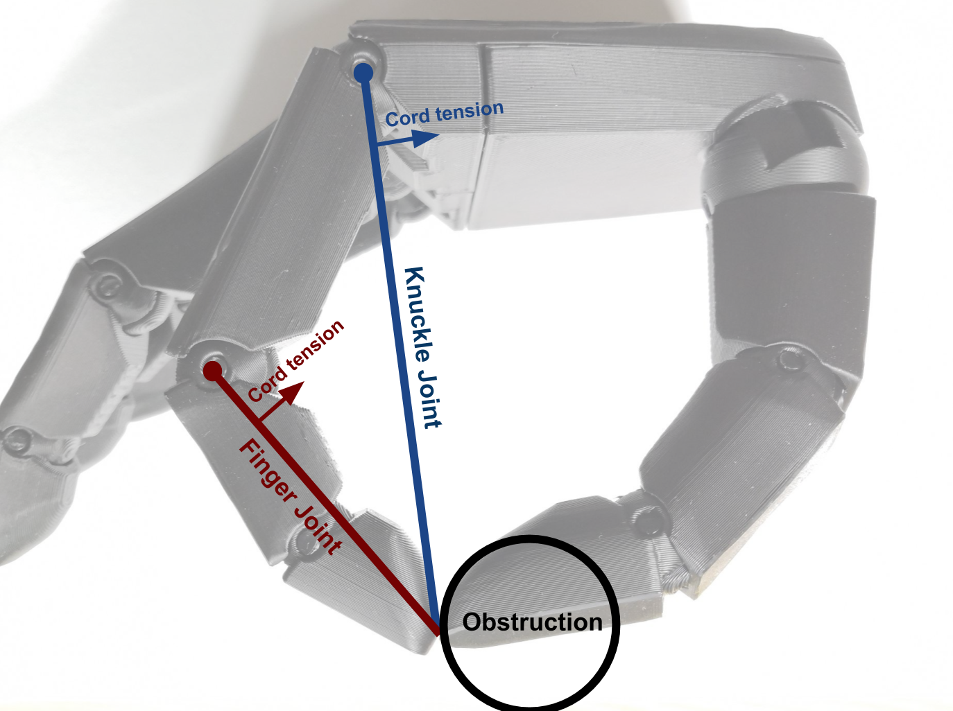
Assume that the above picture is the moment before the finger meets any external obstructions like the thumb that's in front. We know that the angle of the knuckle and finger joint will roughly be equal angles before it meets the obstructing thumb so it gives a starting point. To try to understand what might happen, we can view the fingers as two with their pivot at the joint as show below.
![]()
From above, we can see that the knuckle joint will have the least force transferred as the obstruction is on a longer lever that's further out As the finger joint lever is shorter, it will be able to transfer force a lot easier and therefore there's a higher chance for transmission to be given to the finger joint.
Now as to how the finger will physically actuate will entirely depend on friction as well as other factors like gravity. For a good pinch grip, we ideally want all forces to be directed straight towards the thumb from the fingers. But from the above diagram, we can see that there are some component of forces that aren't directly directed towards the thumb. The components that aren't directed towards the thumb will have to be cancelled out with friction to prevent the finger from slipping away (see results for a better picture).
Similar behaviour was seen when I was testing out elastic bands and TPU/nylon torsion bars, so they all fall under the same category in terms of end result.
Elastic Cord Fingers
A design with an elastic cord may look like it may behave like springs but in actuality the elastic cord in itself may be considered to be an underactuated system. There's one single elastic cord that's actuating two joints in which there's variability between joints. As a result, the elastic cords behave quite differently compared to a finger with springs.
One major effect of elastic cords is that when one of the joints closes, the following joint to close will require an increased amount of torque to actuate when compared to all joints at rest. The effect wouldn't be possible if there aren't any external factors like friction, gravity and obstruction, as the cord would distribute its tension evenly but these factors can be taken advantage of. The two main effects that we can take advantage of are friction and gravity.
When the fingers are open and facing down, there's gravity acting on the fingers to close. Gravity will be acting most on the knuckle joint due to the longer length and increased weight that it has to support when compared to the finger joint. This gives a slight assist to the start of actuation to encourage an easier actuation starting from the knuckle joint.
Friction can affect the elastic cord by increasing resistance to the change of the cord's tension. Whilst the end result of the cord tension will roughly be known, friction will result in areas that may have different tension that would slowly equalise. So when an area is affected by friction, the friction will prevent the cord from equalising with the rest in which it can act as a mild brake for the elastic and preventing it from stretching. Furthermore, as the tension of the elastic cord increases, it increases the friction at the area so mild braking effect further increases.
Knowing these two effects, we can design a finger to take advantage of the effects to improve on the reliability of the actuation of the finger. The knuckle joint already naturally is affected by gravity and the finger joint can be made to introduce friction into the surface when printing.
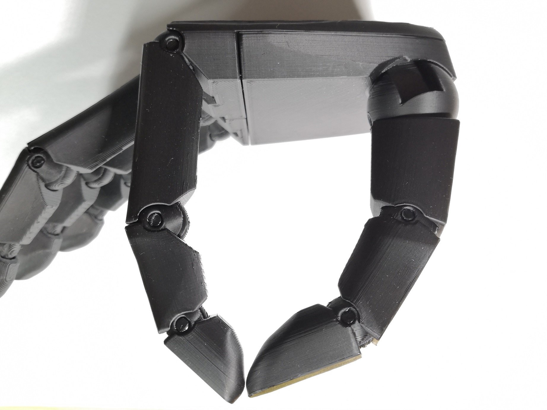
As a result we have a hand that closes as shown below
![]()
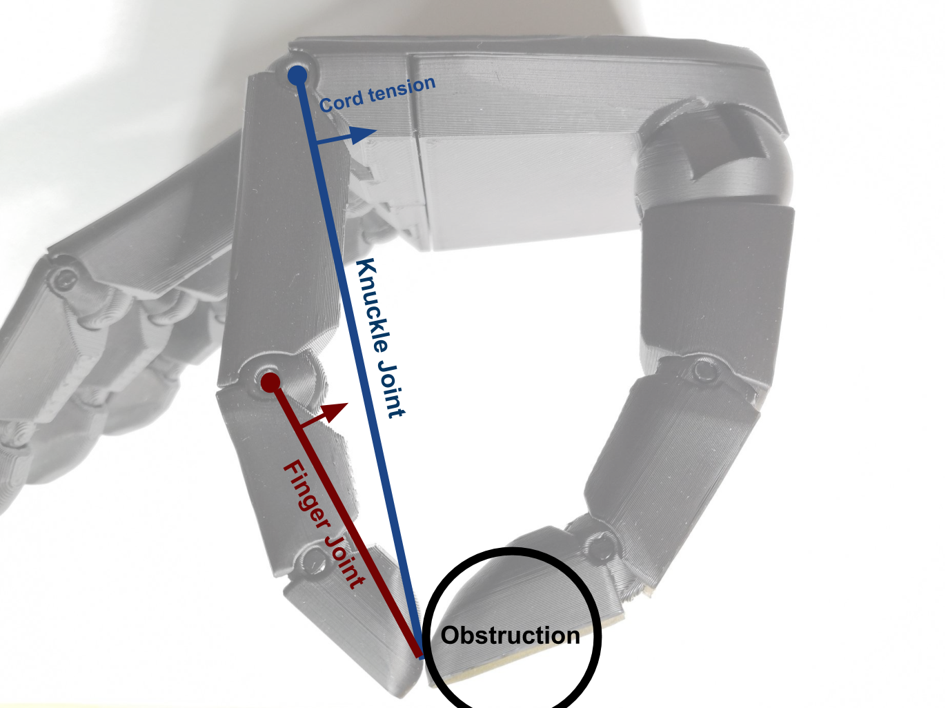
Adding on top of the image with some levers we get the diagram below
![]()
We can see that there's a lot less unwanted component of forces that aren't directly directed towards the thumb as the finger joint is fully extended whilst the knuckle joint is almost fully closed. This is the main reason why I settled on using an elastic based design as well as other reasons like ease of assembly and source.
Rough Quick Test Results
Spring based system
This initial test with a spring based system is with a 0.4mm wire torsion spring on each joint. The finger tips are coated in Sugru to provide a slightly better grip.Testing of the finger did not show desirable results as the finger wasn't able to wrap around the item and slipped off soon after when actuating.
- Finger with even springs [GIF image]
![]()
A possible fix would be to increase the torsion spring torque at the finger joint to reduce the effect of having an equal angle for knuckle and finger joint. Fortunately, my design is able to accommodate a second spring so it's just a case of inserting a second spring at the finger joint.
Testing of this version shows a lot more promising result, however, it brings into consideration if it is worth the effort to accommodate different torque requirements at each joint when it can be achieved with just a single elastic. Durability will definitely be a lot better if using springs.
- Finger with uneven springs [GIF image]
![]()
Elastic based system
This test uses a basic 1mm elastic cord on the back of the finger.Testing shows a very desirable result with the finger wrapping around the object before pushing away the object when actuating
- Finger with elastic cord [GIF image]
![]()
Additional Notes
Testing has only been done with the finger that I've designed so it may vary with other designs. Things like tendon cord friction, joint diameter, material choice, etc can affect the overall outcome.
There are some quite significant downsides to using elastic however especially in terms of durability. Depending on the material choice, desired elongation, tension and temperature, the elastic may stretch or lose it's elasticity. Some materials like TPU may have high elongation but when left stretched, the material can end up deforming and changing lengths. This is especially prominent with TPU printed elastics where it may be able to sustain short periods of stretching but will deform if stretched for long periods. This is the main reason for adjusting the design to have easily replaceable elastics.
Disclaimer
Take whatever I write as a grain of salt. I am in no way an engineer so treat it as some random person writing on the internet. What I write is just what I personally observed and had tried to come up with a reason behind it. Anything may be wrong so don't take it as legitimate information.
-
Notes on 3mm and 2.85mm pins
09/04/2020 at 12:57 • 0 commentsWhilst helping to search for a source of filament pins for the ARX Hand Project, I had noticed that most large diameter filaments are sized 2.85mm in diameter. At the time of purchase when starting the projects, there were filaments that were sized to exactly 3mm for some reason. Current standard filament sizes are 1.75mm and 2.85mm, so I'll have to make adjustments to the design to allow for accommodation of either sizes. I won't fully move to 2.85mm as 3mm is a more common size for things like shafts and drill bits as well as some 3mm round nylon trimmer line if accessible (another possible source, 3mm nylon draw tape for cables). Nylon is still the recommended material for joints rand ratcheting mechanisms but if there isn't a source for a nylon sample, other materials may be used but will impact on performance and durability. Carbon fiber nylon is also another option to provide for a more stiffer material.
Currently, MK0M and MK0S have been updated to accommodate for either pin sizes.
-
Single Joint Finger Alternative
08/21/2020 at 12:52 • 0 commentsI've created a drop in replacement single joint finger that's interchangeable with existing 2 joint fingers. A single joint finger allows for more precise control of finger actuation without uncertainties resulting from the under-actuation of joints in the 2 joint finger. Although features have been implemented into two joint finger to improve consistency in initial actuation for use in pinch and tripod grip, a single joint finger completely removes the uncertainty that results in the 2 joint finger as the amount actuated directly equates to the angle of the finger.
Features:
- 1 joint and 2 joint fingers are interchangeable on MK0, MK0M and MK0S
- Reduced required actuation length
- Semi sprung joints
- Allows for more precise tripod and pinch grip
- Length actuated equates to angle of finger![]()
-
Semi Sprung Joints
08/21/2020 at 12:51 • 0 commentsSemi sprung joints are used in the finger tips of the V3.3 finger and in the V1.2M thumb developed for the MK0M mechanical hand. Added compliance of thumb and finger tips provides a better distribution of surface contact compared to a rigid design. Design doesn't require special hardware like custom springs and only relies on the flexibility of nylon. Initial attempts of a semi sprung joint were tested in the first MK0 prototype with TPU pins, but were found to be too soft for the task. Nylon gives a good balance of flexibility and stiffness as well as being fairly tolerant to deformation in the design.
![]()
-
Experimental High Torque Bi-directional Ratcheting Mechanism
06/13/2020 at 01:10 • 0 commentsActually, would this joint be considered a ratcheting joint or a joint with indents?
This design looks into the use of a ratcheting mechanism for use within the wrist section of the arm. I'm not entirely certain on what mechanism would be ideal for prosthetic use, however, I had decided on a ratcheting mechanism for wrist design over a locking, friction or fixed joint. I felt a ratcheting mechanism would be the easiest for a user to operate with, and would be fairly easy to implement. A friction joint would have a similar user operation and better user adjustment, however, I felt it may be difficult to implement reliably and to have sufficient friction to resist unintended rotation. I do feel it would be possible to create a friction joint however, so may look into creating one in the future. For a locking joint, whilst it would be acceptable for a single hand amputee to operate, it may be difficult to operate the locking mechanism if they are a double hand amputee.
The design I came up with further develops on the method of using nylon filament as a flexible low wear material. Compared to the mechanism I had used in the thumb joint, this design takes a different approach to achieve a ratcheting mechanism. The ratcheting mechanism in the thumb joint relied on the flexibility of the nylon axle to act as the spring of the mechanism, and a piece of short nylon to act as the low wearing indent. There is a limit on how much ratcheting resistance the thumb joint design would allow so a different method would be required.
[image to be added]
As it would be ideal to have the wrist joint as compact as possible, I started from reusing the short piece of nylon filament used in the thumb joint. To make a reliable joint, wearing surfaces should be made with a low wear material, and ratcheting parts should be made from a flexible and durable material. Nylon fits the requirements so I decided to integrate the design around having the short nylon piece as the bearing material as well as the ratcheting component. Therefore, a section of the nylon will provide the bearing surface, whilst another section will give the flexible component that rides over an indent to provide the ratcheting feedback.
[image to be added]
For a wrist joint where there may be cables or wires that need to be passed between the hand and arm, the joint should have a open pathway at the center axis of rotation. Having cords at the center constrains the movement of the cords in only at a twisting motion, rather than an increase in cord length when routed outside of the center axis of rotation.
[image to be added]
Having a basis of knowing how the mechanism should be designed, I settled on laying out the design similar to a ball bearing, where you have an inner and outer race along with ball bearings which will be nylon filament in my design. The only part that differs from a ball bearing is that the rolling elements will be fixed, and will be sliding instead. A major benefit to the layout is that the number of nylon elements can be reduced or increased depending on design requirement. Indents can be small to improve long term reliability whilst an increase in nylon elements can improve load bearing capabilities as well as distribute wearing effects of indents. Changes to indent size and quantity of nylon elements allows for a large variety of applications where this method may be suitable, however, there will have to be a balance of functionality and reliability.
[image to be added]
Printing out the design, I was well impressed by the torque required to overcome the indents which I had designed to be 1mm (which thinking now might be too aggressive). Despite requiring a wrench to overcome the indents, the mechanism seemed quite reliable as there wasn't a perceivable degradation from ratcheting the mechanism many times but should really be checked out with some equipment. I decided to reduce the indents to suit my requirements but with quick manual test, the design shows a lot of promise as a high torque ratcheting mechanism which can be used in many applications.
-
V3.3 Finger Design
06/11/2020 at 19:07 • 0 commentsV3.3 builds on top of the initial design for V3 finger design. The aesthetic design remains the same, but many optimizations have been made to the design to improve overall printabilty and assembly.
Subtle features have been added within the model to reduce effects of 3D printing imperfections from impacting the fitting of joints. Rounding to edges have been added to reduce overshooting artefacts on surfaces from ghosting, ringing and nozzle pressure build up, and seam adjustments have been added to avoid seams being placed between joint surfaces. Clearances on the joints are still fairly lenient to allow for easier printing, but clearances may be reduced down to 0.1mm if required.
For a two joint finger, fingers require the use of 1.75mm and 3mm nylon filament to act as pins between joints. Nylon should ideally be used as it provides a low friction, low wear joint. The flexibility of nylon also allows for a springing effect of joints, as well as to aid with friction fit joints through deformation of the material.
For closing actuation, fingers are actuated through a single cord of 0.5mm to 0.8mm diameter braided fishing line attached using a screw. For opening actuation, fingers are opened using an elastic material attached on the back side. The method of attachment of the elastic material allows for a number of options that available or easily accessible. Elastic cords can be used through tying knots at ends, and elastics can be printed or made through casting, injection moulding, die cutting, etc. Detachable cords also allow for easy replacement or disassembly of fingers.
The positional consistency of V3.3 finger has been improved for better grasping when used in tripod or pinch mode. Ideally for the current design of ARX Hand, the actuation force should be directed towards closing the knuckle joints without closing of the middle-proximal joint. Because of the under actuation of the joints, the closing of joints depend on the resistance of actuating each joint and how the fingers may be obstructed. If there's even actuation resistance between each joint, the joints will close evenly with the middle-proximal angle roughly equal to the knuckle angle. But due to how the fingers are angled and the effective leverage distance on contact upon closing in on the thumb, actuation force will be directed towards the middle-proximal joint
Fingers can be printed without supports for little to no post processing needed for assembly. Supports may however be required if there isn't enough adequate cooling for overhanging areas. Additionally, TPU grips can printed to improve functionality of fingers with grasping objects.
Features
- Easy assembly and disassembly
- Flexible choice of elastic materials
- Interchangeable system
- Durable and impact resistant design
- Improved positional consistency of finger actuation
- Low post clean up requirement
- Cleaner prints with adjusted seam placement and rounded edgesFurther work
- Printed TPU pads don't provide a significant amount of grip so grip needs to be improved
- Find what could be used alternatively for grip on fingers
- Look into possibilities with printing or casting finger tips out of TPU
- Look into if there are extension springs that can be used as an additional option to elastic cords
- Possibly implement features to reduce play in joints
- Improve placement of the end of the tendon cord -
Experimental Opening Mechanism Designs
05/10/2020 at 20:12 • 0 commentsRoughly 6 possible designs have been made for returning the fingers back into an open position. There are a few others that have been used in previous prototypes but they were created more specific to the design requirements of those prototypes. So far, most of the prototypes have used an elastic cord on the back of the fingers to return them back into their open position. Elastic cords are fairly easy to obtain and assemble into the design, so it had been quite extensively. Main issues with elastic cords (dependant on material) is the long term durability in physical wear and loosing elasticity over time.
Roughly 6 designs were printed to test a number of different elastics and methods of opening fingers. 3 of the designs are elastic based, 2 are torsion bar based and 1 is a torsion spring based joint.
- 1mm elastic cord -
Used as a reference to compare with. - Rubber bands -
Functions well, however, finding a source for a specific sized elastic band can be difficult. Finger design doesn't have enough space to easily allow for a choice of different sized rubber bands. - Printed elastic -
Requires a bit more force to actuate. Easy to assembly as length is printed. Not suitable for stretching for long periods as it results in the material stretching. - Torsion TPU -
Fairly easy to print and assemble with the torsion bar printed in TPU. Actuation force is similar to the elastic cord design and returns to position when released. Joints are rather flexible and can be forced beyond its intended position which can result in the actuation cords being pulled further than intended. If there isn't slack in the system, the cords being pulled may result in damage. As the finger joints aren't particularly completely constrained, the load bearing capabilities aren't as high which results in greater actuation force. - Torsion nylon -
Doesn't require printing of the torsion bar but performs very similarly to the torsion bar printed in TPU with similar issues and effects. - Torsion spring -
Uses 0.4mm steel spring wire wrapped with 2 coils around the 3mm axle and inserted between the joints. Functions with similar actuation force as the rest of the test designs. Design would be fairly reliable if compared with longevity of the elastic designs. Main issue with torsion springs is the difficulty in sourcing and making through DIY methods. The cavity used also adds to print complexity which can make it hard to print.
Overall comparing the designs, I decided to settle on the elastic cord design as it provides the easiest design to source parts and assemble.
![]()
- 1mm elastic cord -
-
Adapter PCB for V1 PCB 010
01/13/2020 at 07:36 • 0 commentsAdapter PCB made to accept an Arduino Nano or any similar board to interface with V1 I2C PCB. This reduces the requirements of having to manually wire the connections similar to the photos on V1 hand prototype. Adapter PCB also bring added debugging LEDs for quick diagnostics.
Features
- RGB Status LED
- Supporting LEDs for drivers that aren't on the V1 PCB
- Broken out pins for additional interfacing
- Screw terminal for power connectionsSpecs
- WS2812 LED on D2
- Mainly 5V based
- Breakout connections: GND, 3.3V, A0, A1, RX and TX
- Pull up LEDs added for RD0 to RD3
KiCAD: https://kicad-pcb.org/
Arduino 33 IoT CAD Model:
https://grabcad.com/library/arduino-nano-33-iot-1 -
V2.1 Hand PCB
01/03/2020 at 04:45 • 0 commentsNew PCB development with better integration between drivers and microcontroller. PCB now uses Arduino Nano style footprint to allow for change between different microcontrollers, such as the Arduino Nano V3, Nano Every and Nano 33. Reverse polarity, short circuit protection and battery voltage level have also been added with the use of a P-Channel MOSFET and polyfuse.
Features:
- Arduino Nano Footprint
- Reverse polarity protection, P-Channel MOSFET
- Short circuit protection, Polyfuse
- Battery voltage level, through A7 pin
- Screw terminal power input
- Improved spacing for motor connections
- Broken out connections for GND, 3.3V, A0, A1, I2C and TTL SerialSpecs:
- 6V max operating voltage
- I2C motor driver interface
- Battery voltage level = (voltage at A7 pin) * 2
- D2 to D5 are used for limit reading for M0 to M3
- Breakout connections: GND, 3.3V, A0, A1, SDA, SCL, RX and TXFurther Work:
- Better location for breakout connections
- Use of compact wire-to-board connectors
- General PCB design improvements for hand, e.g. smaller footprint, more features, etc.
KiCAD: https://kicad-pcb.org/
Arduino 33 IoT CAD Model: https://grabcad.com/library/arduino-nano-33-iot-1
ARX Hand Project X1
An advanced low cost 3D printable robotic hand for development in robotics, animatronics and prosthetics