2.4GHz and 5GHz IEEE 802.11.b/g/n/ac wireless LAN, Bluetooth 4.2, BLE
Gigabit Ethernet over USB 2.0 (maximum throughput 300 Mbps)
Extended 40-pin GPIO header
Full-size HDMI
4 USB 2.0 ports
CSI camera port for connecting a Raspberry Pi camera
DSI display port for connecting a Raspberry Pi touchscreen display
4-pole stereo output and composite video port
Micro SD port for loading your operating system and storing data
5V/2.5A DC power input
Power-over-Ethernet (PoE) support (requires separate PoE HAT)
Although we could choose a basic Arduino microcontroller to do all the connectivity and programming between these basic sensors. Reason to choose this over Arduino is that future expansion of on-board sensors will allow us to better view, control, and program them by connecting the robot wireless using ssh terminal. Reprogramming won't demand physical connection. Furthermore, all necessary indoor communication modules (Bluetooth and WiFi) are installed on board, which saves us space and hassle of connection.
Linux operating allows the flexibility to modify operating to custom requirements. It also allows us to use python and C to directly communicate with sensors and actuators, which can then be used to apply plethora tools to analyze the data using machine learning algorithms. Logged data can then be used to train models which can then be directly executed on Raspberry Pi.
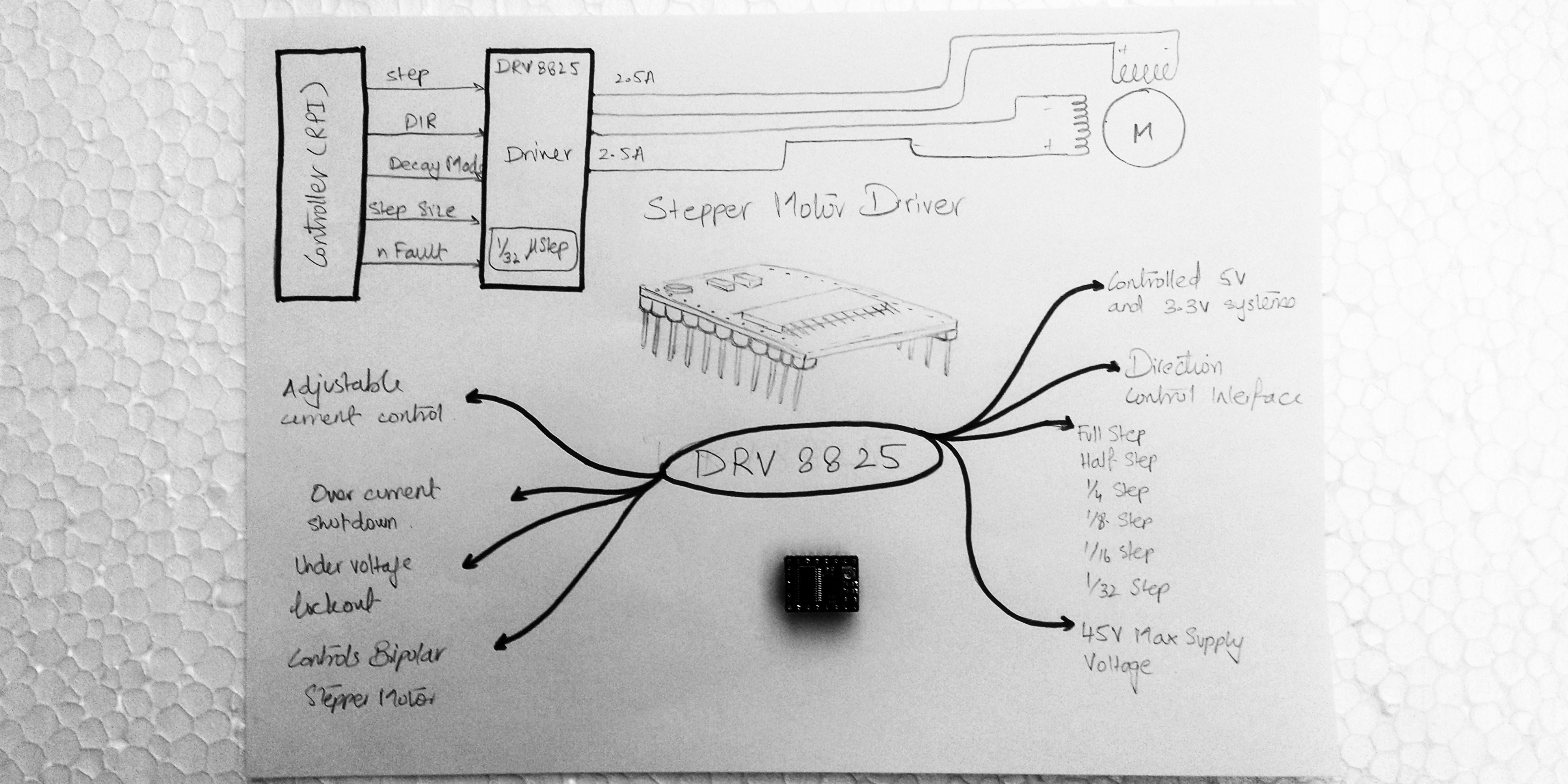
DRV8825 Stepper Motor Driver
The DRV8825 stepper motor driver has output drive capacity of up to 45V and lets you control one bipolar stepper motor at up to 2.2A output current per coil. The driver has built-in translator for easy operation. This reduces the number of control pins to just 2, one for controlling the steps and other for controlling spinning direction.
Features:
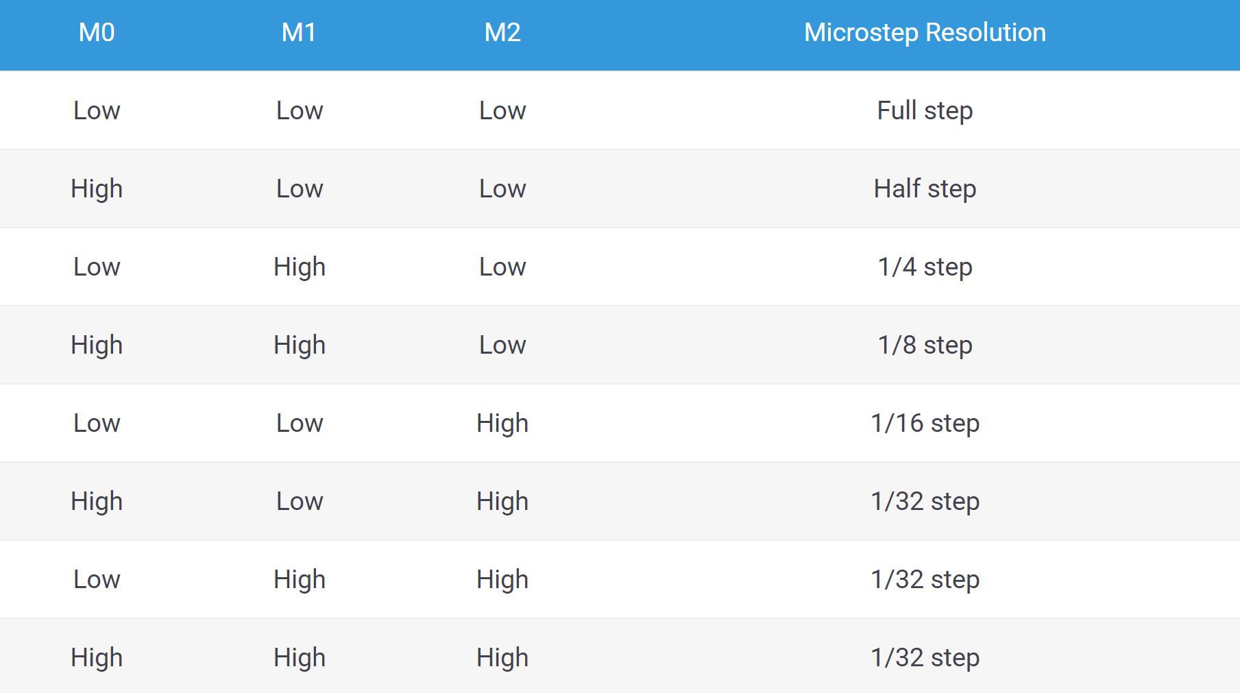
Six step resolution: Full step, ½ step, ¼ step, 1/8, 1/16 and 1/32 step
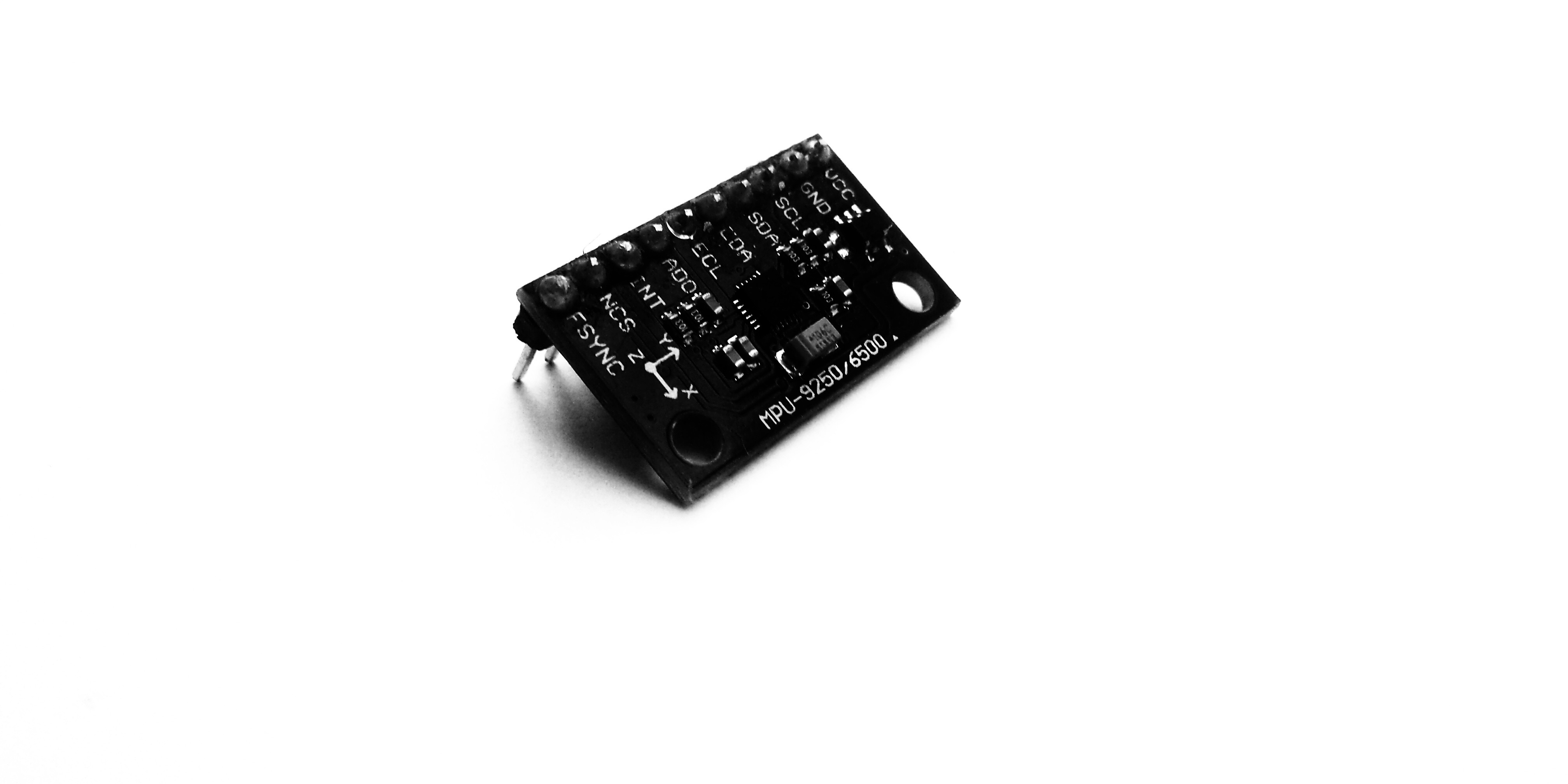
The MPU 9250 object reads acceleration, angular velocity, and magnetic field using the InvenSense MPU-9250 sensor. The MPU-9250 is a 9 degree of freedom (DOF) inertial measurement unit (IMU) used to read acceleration, angular velocity, and magnetic field in all three dimensions.
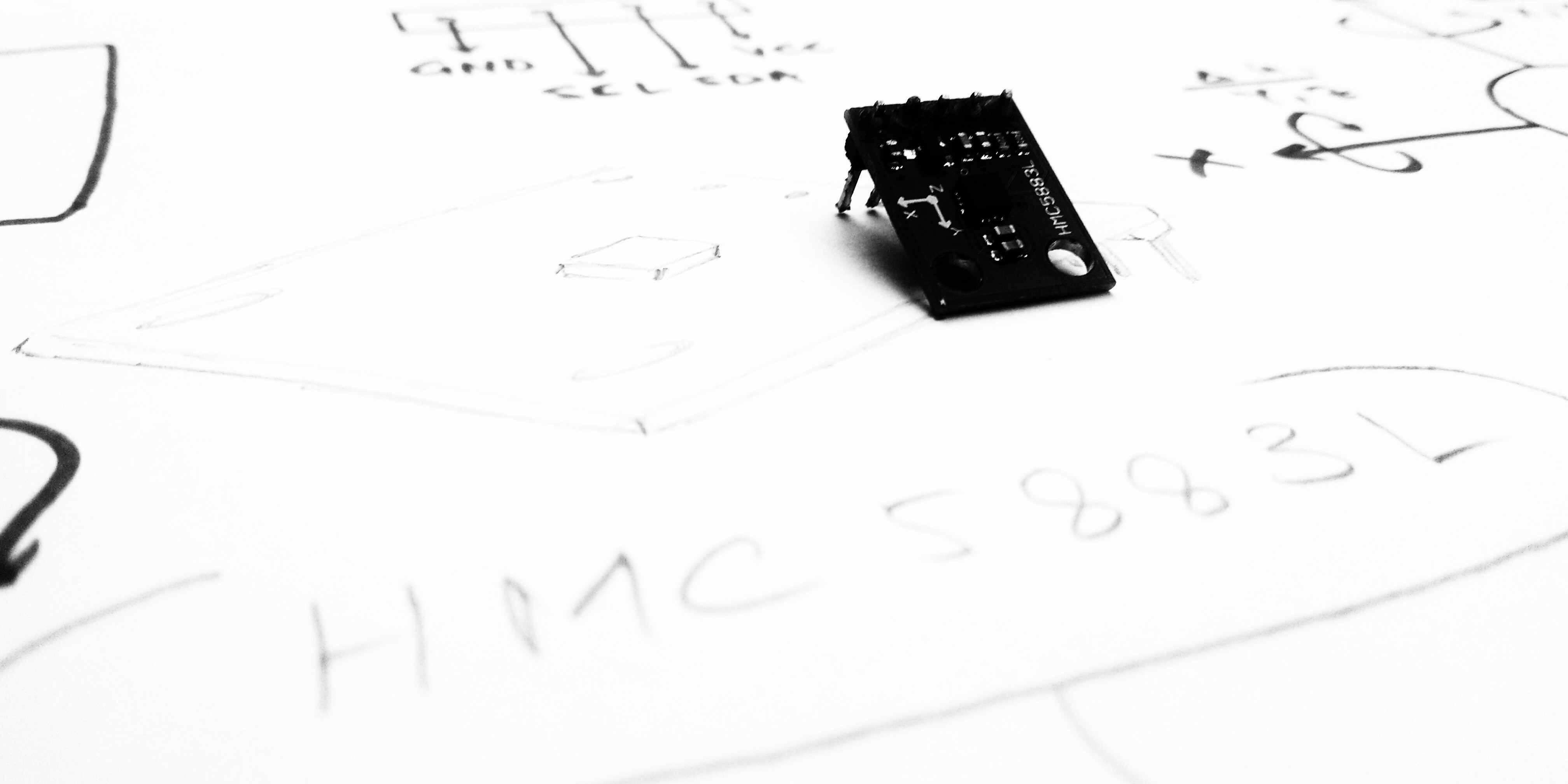
The 3-Axis Digital Compass HMC5883L sensor is able to acquire information even in a low magnetic field. Distributed over the three axes, this information is converted into a differential voltage of 2.7 to 6.5 VDC to provide input for a vast range of microcontrollers operating at different voltages.
The raw digital output value can be used to calculate direction and location, and for measuring both the magnitude and the direction of the Earth’s magnetic field in cases where the robot needs to measure several magnetic fields coming from different directions.
Writing 3 bit binary code on pins M0, M1, M2 allow for change in micro-step resolution. This is results in overall fine control of the motion of the robot.
The STEP Pin input controls the micro-steps of the motor. Each HIGH pulse sent to this pin steps the motor by number of micro-steps set by Micro-step Selection Pins. The higher the frequency, the higher the rotational speed of the motor.
The DIR pin input controls the spinning direction of the motor. Pulling it HIGH drives the motor clockwise and pulling it LOW drives the motor counterclockwise.
 NEBRA Labs
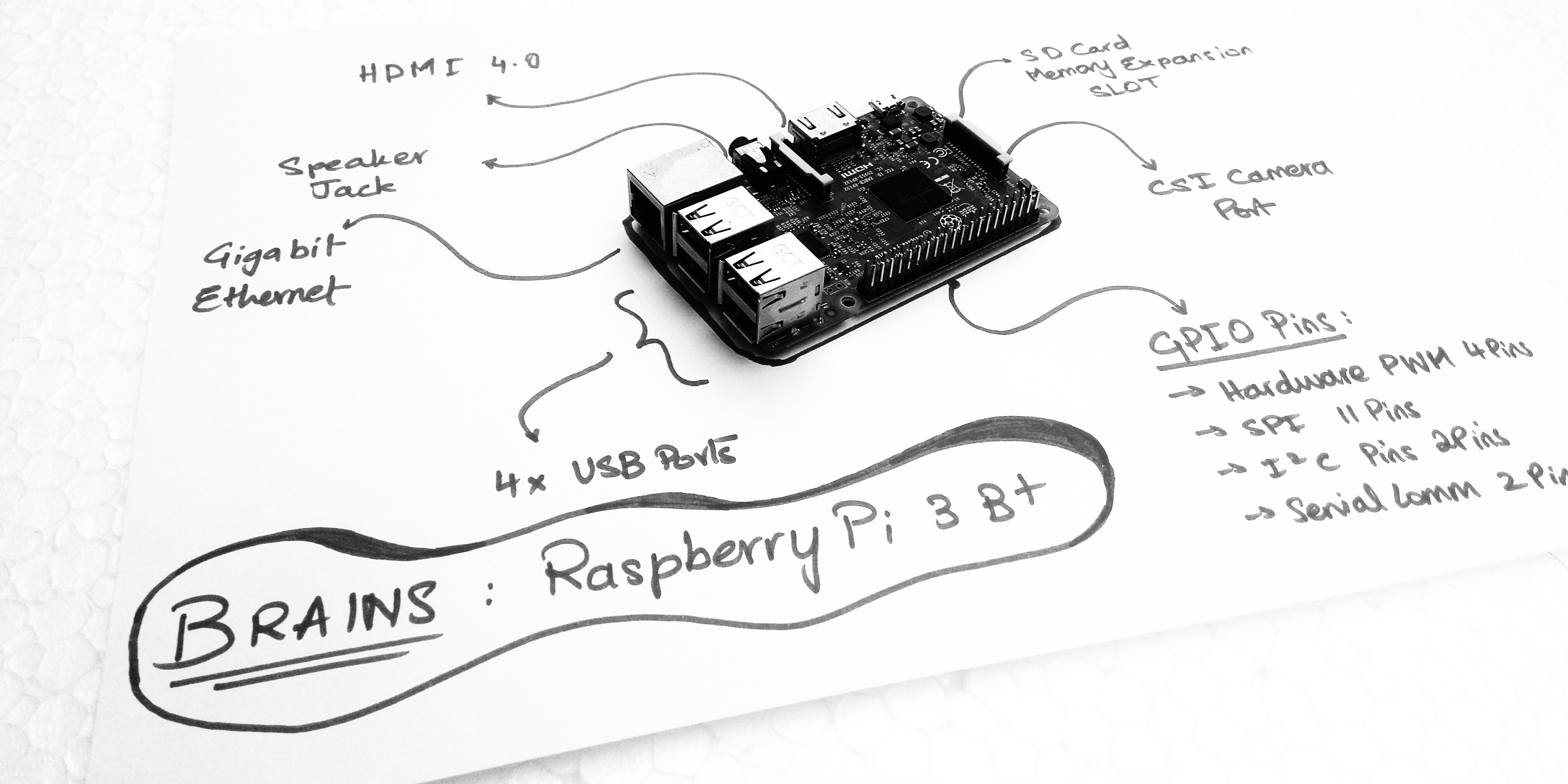

Discussions
Become a Hackaday.io Member
Create an account to leave a comment. Already have an account? Log In.