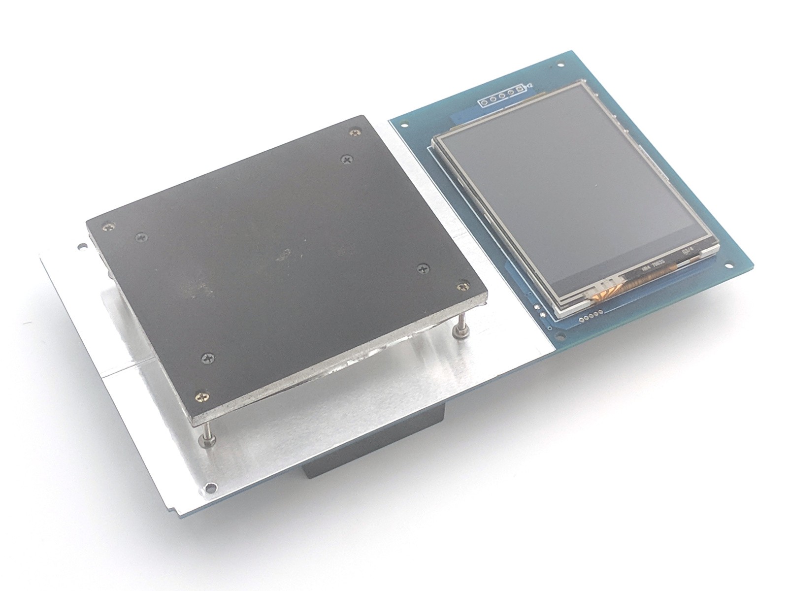
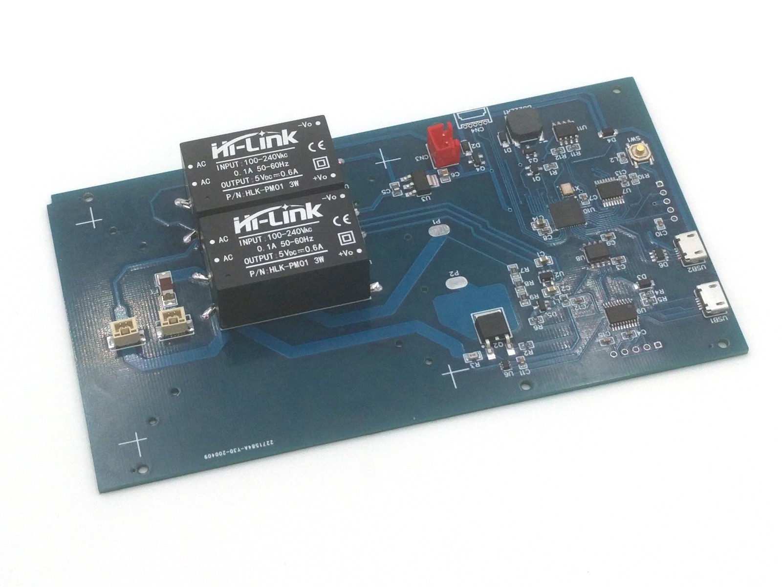
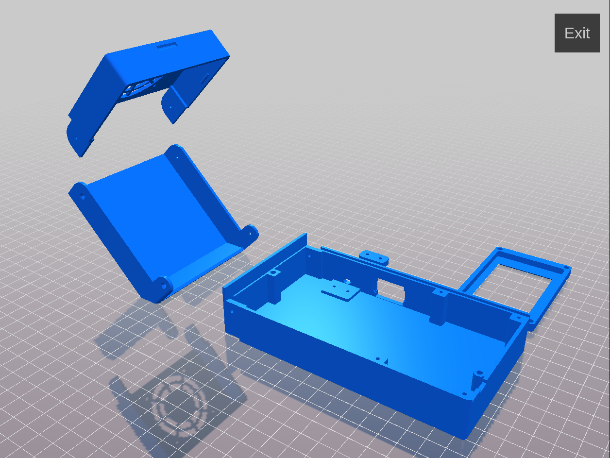
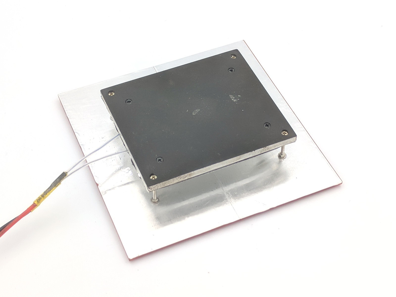
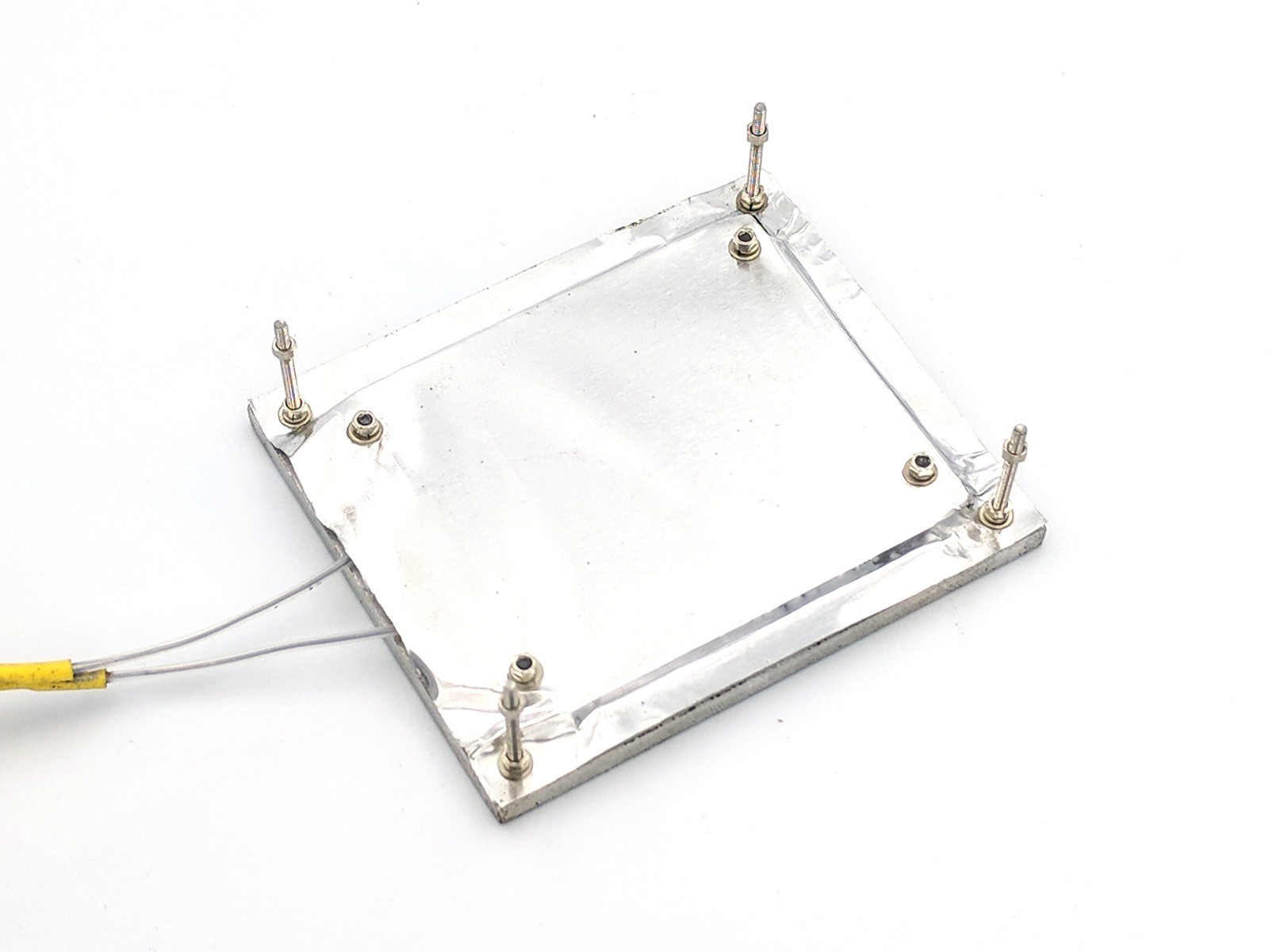
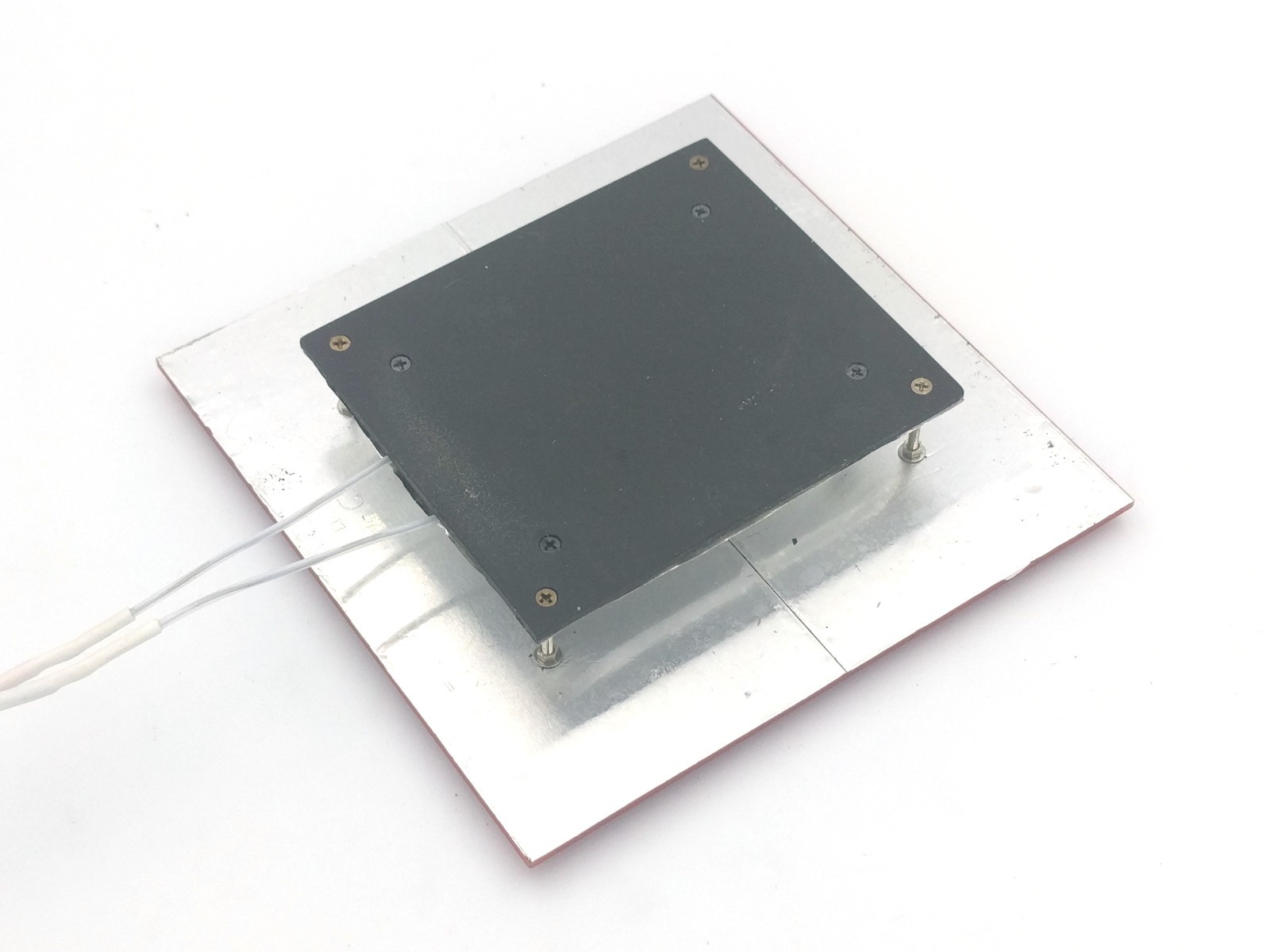
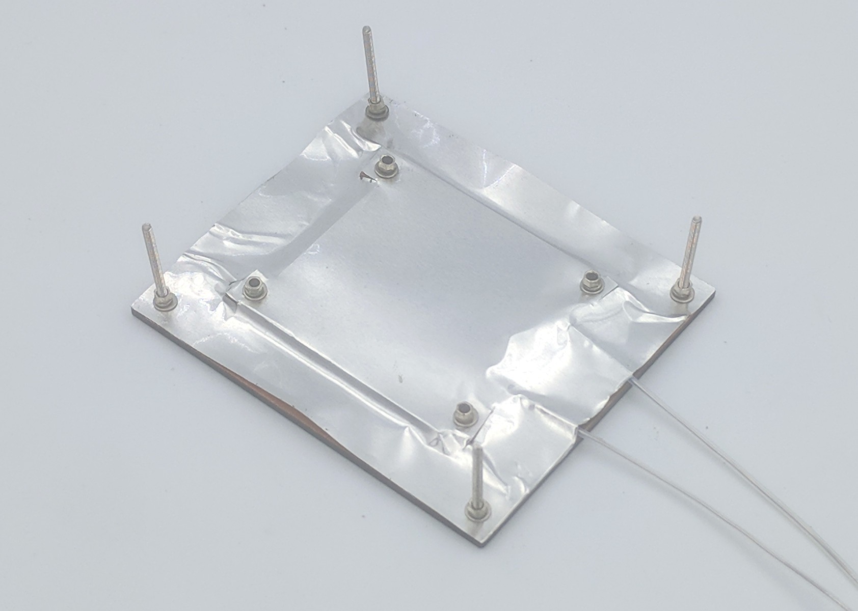
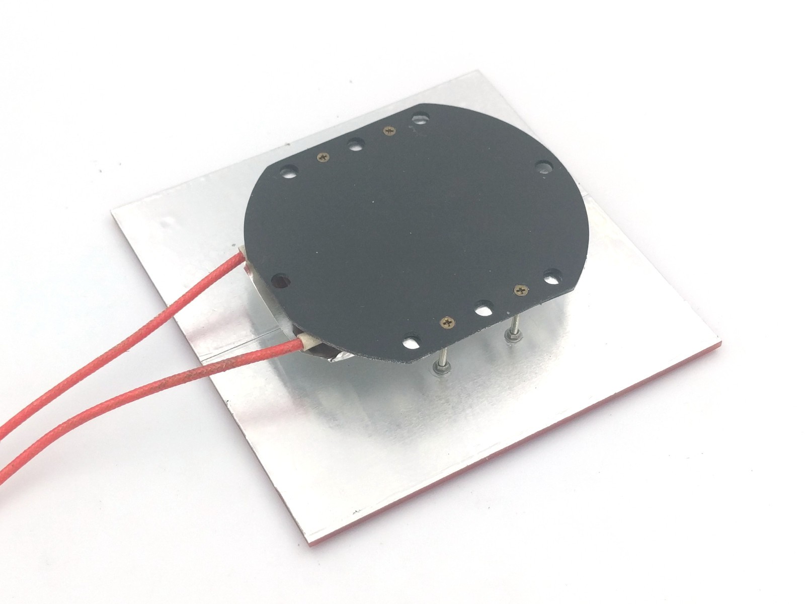
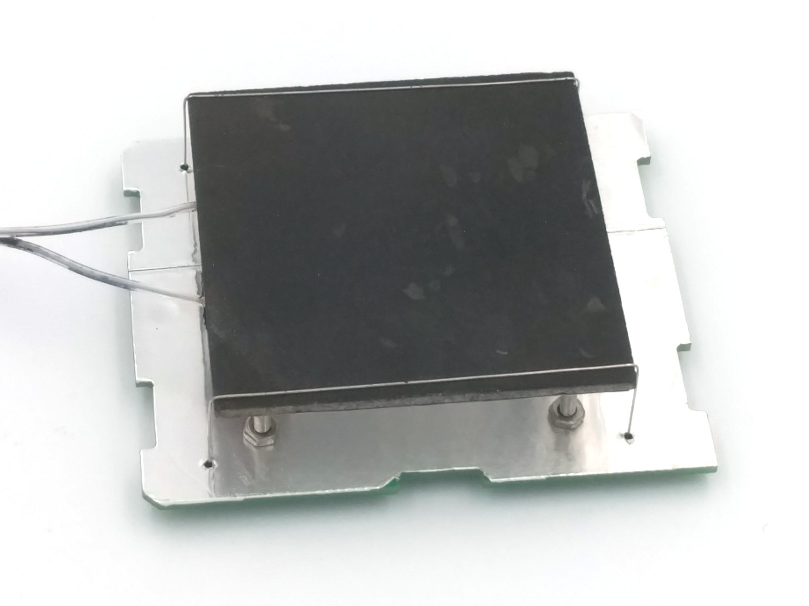
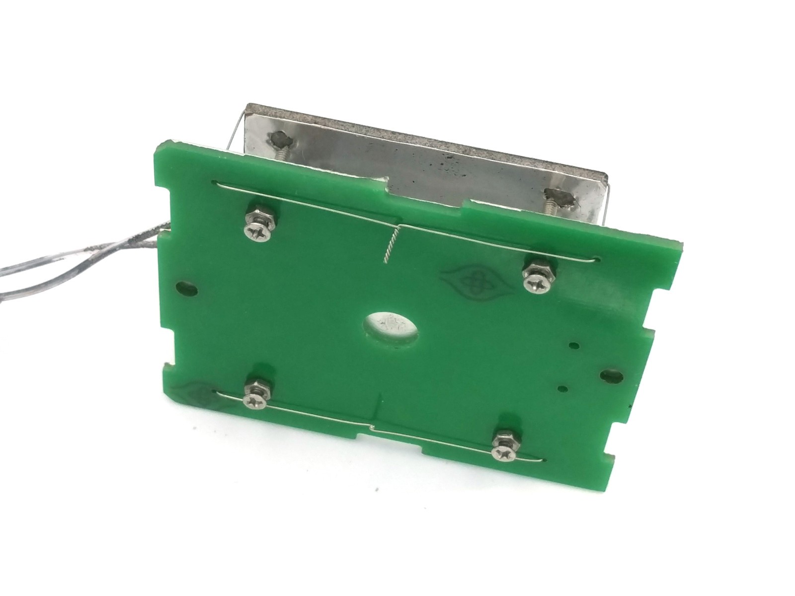
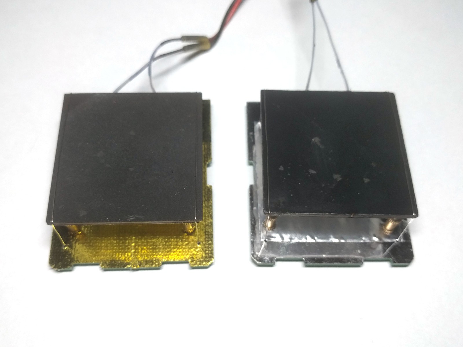
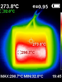
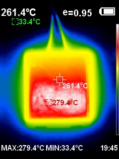
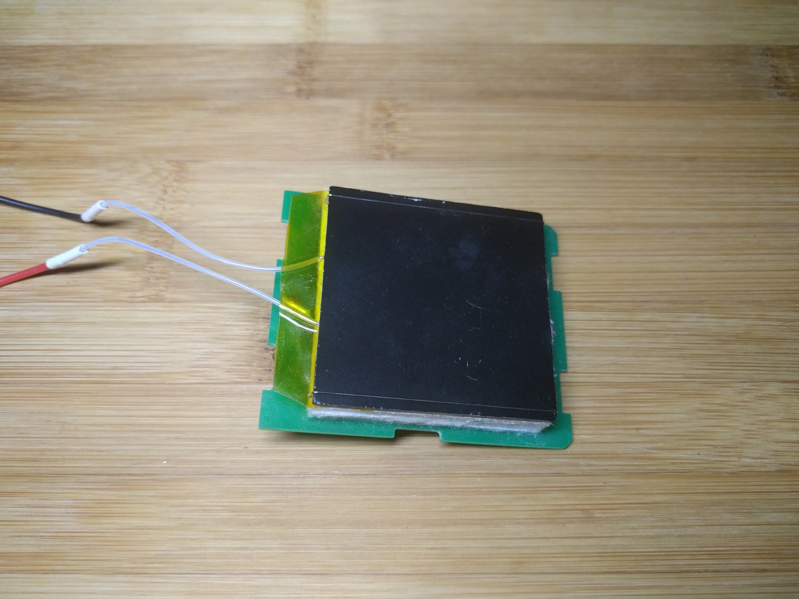
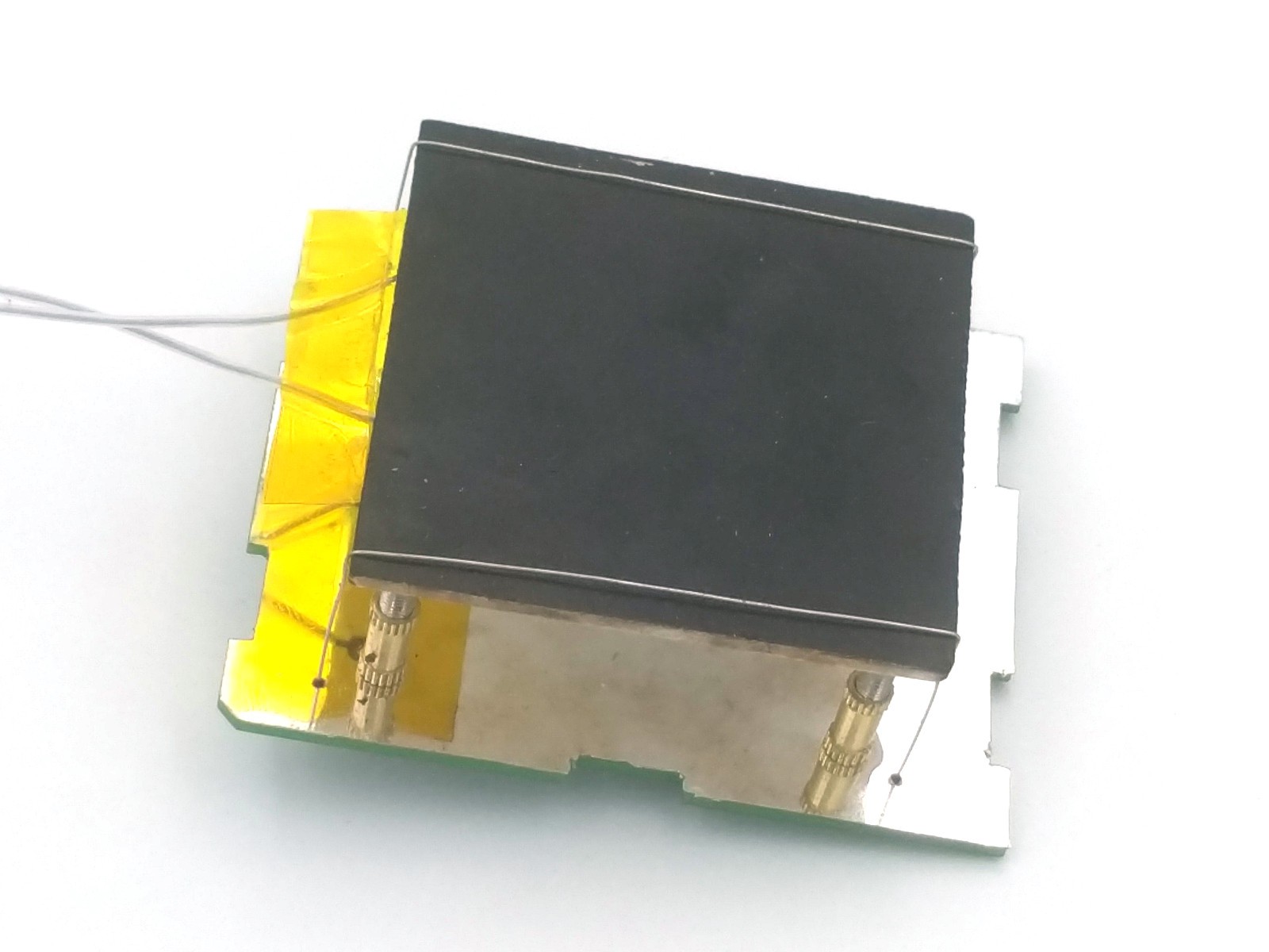
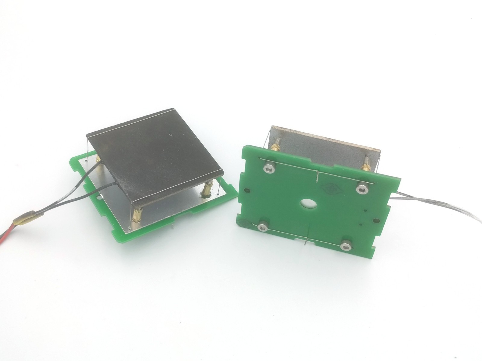
Micro table to reflow small boards.
To make the experience fit your profile, pick a username and tell us what interests you.
We found and based on your interests.
Finally, assembled couple of PCBs:
Now can debug drivers and print case.
I'm still thinking about USB-PD version. It should contain less components and be more compact. Anyway, software architecture is flexible enough to support both. We will continue with current PCB to test usability, and will order USB-PD version in parallel.
Finished drawing PCB & case:
All links & sources are on github: https://github.com/puzrin/reflow_micro.
Now plan to spend several days for additional checks. Then will order components and try to print something working until electronic parts arrive.
Made more heaters with plates of different thikness, to test temperature difference. Thermal camera shows only general picture, so used K-thermocouple via drop of rose metal to check most hot (~ center) and most cold (corner at wires side) points. Checks have been done at medium (~ soaking) and high (~ peak) temperatures.
4mm:
3mm:
2mm:
As conclusion - 4mm plate is good for any cases. It still can be cooled fast enough with fan.
Pictures of winner:
PCB is already complete: https://easyeda.com/reflow/reflow-micro-table. But i'd like to draw device case and verify PCB outline and other things.
Finally tested a lot of ideas & new method of MCH mounting:
Here is "almost final" candidate:
Bottom:
All assembly details and more photos are published on gihtub (will be updated soon): https://github.com/puzrin/reflow_micro/blob/master/doc/heater_assembly.md
Not everything was fine. Unfortunately, rejected aluminium heater cartridges:
Also, i had to reject copper plates in favour of aluminium. Copper is oxidised too fast on high temp. I hoped oxidised film to stop process, but it crumbles after big temperature change. Probably, this can be fixed by protecting plates with paint from all sides, but that's not convenient.
40*40*1.7mm MCH heaters were tested, but found 50*50*2mm more comfortable. Price difference is very small.
As been said, new approach looks good at first glance, and now it's safe to route PCB and design 3d-printed case. All next experiments can be done in parallel.
It still worth to clarify plate thickness. 2mm aluminium plate gives ~ 15C difference in working area (5mm margin from borders). That's enough, with big reserve, for leaded paste (i doubt anyone use lead-less paste for hobby projects). But it would be nice to improve if possible.
I'm waiting 3mm and 4mm alu sheets for new plates and hope to publish final decision & measurements next week.
While thinking about device layout, remembered interesting idea about temperature measurement. MCH heaters use wolfram film routes inside ceramic. Wolfram has big TCR, about 60% per 100C. So, we can use heater's resistance to measure temperature precise enough, without any additional sensor. The same method is used in vape mods with temperature control.
If no need to mount sensor, that extends the list of available components. Try to search "LED Remover Heating Plate" on AliExpress. You will see nice interesting plates like this one. I don't know how good are those (temperature gradient and cooling speed), but worth to try. Unfortunately, those alu-coated plates are 220/110 volts only.
I need to decide, does it worth continue with USB-PD, or switch back to AC. Bellow are summary of differences.
AC powered (with alu-coated MCH):
For AC, resistance control can be done with "energy meter" chips (BL0937, HLW8012).
I've ordered "aluminium heater", referred above, and wish to test it before moving forward. Hope this to happen in 2-3 weeks.
Let me know what do you think. I'm sorry, if USP-PD is critical for someone. But i hope any planned changes will do project better - still very small, but more simple, and so on.
Finally achieved very good results: MCH top 260C, bottom mount points 45C (screw heads), PCB almost cold. Only 10mm space between PCB and MCH. That's a win :). See photos and read details below.
Idea is very simple - take 2 thin SS screws, sharpen ends and mount to PCB with 2 nuts from both sides.
Screw sharpening can be done with screwdriver and hand grinder:
If your screwdriver has axial oscillations, cone will be not symmetric, but that's not principal.
What is important:
After all, assembled device can work many hours (was tested!), and keep PCB slightly warm. The most hot points are screw heads, and those are only 45C.
Finally, i have working solution to move forward:
But in real device I plan to use M1.6 screws (almost twice less section than M2) and check additional things:
Now, time to route PCB :). All details will be at https://easyeda.com/reflow/reflow-micro-table.
Finally, after waiting for new materials, checked some ideas and here are new details about MCH mounting.
New heroes :)
Right is with:
Don't pay attetntion to dirty surfaces, that's after testing coverage quality.
I wished to find better replacement for high temp silver paint. Classic solution to reduce IR emission is aluminium foil. So, needed to find suitable foil thickness (convenient to work with) and suitable glue (good at 300-400C).
First, any foil is ok to reduce (or reflect) IR emission. But too thick foil may be not convenient for mount. After search, i found nice foil in disposable aluminium baking forms :). It's ~ 60um thick (kitchen foil is 10-20um), cheap and easy to buy. The only advice i can give - select form with flat bottom.
Glue is a different story. There are only 2 types of accessible glues for desired temperature range:
Problem is, we need thick layer, and this glues dry not well without air. Also, cement is not convenient for work.
Since foil on MCH bottom does not need full surface bonding, we can use gasket maker. If we put small glue points on corners and between, that will be enough to hold foil well. And glue will dry completely in 1-2 days.
I selected copper-filled gasket maker, to use it again later as thermally conductive glue for RTD sensor.
How to bond:
I had idea to use Panasonic PGS to equalize surface temperature. But, to be honest, amount of problems are not proportional to added value.
Of cause, there are 2-component epoxies and thermally-cured 1-component glues, able to work at 300+ C. But those are not cheap, and not widely available.
Here are 2 thermal images, as a result of experiments. Don't be too critical to temperature values - i used different paints and did not tuned camera.
Ordinary black top:
Top with PGS (poorly bonded with copper-filled silicone gasket maker):
So, may be, PGS can help a bit, but it's not "magical" for this appliance.
My opinion is - use any black paint, able to work at 400C and more. Usually, all such paints have good adhesion to ceramic. So, select the cheapest one. Take care to manial, usually after dry, heating at 180C (or more) required for 1-2 hours. Since we paint heater - that's not a problem at all.
As you can see on thermal images, ~15-20mm from power wires are not heated well. The rest is ok, if we do some discount for hobby use:
I'd say, there will be ~30*45mm of "solderable space". Very nice.
Is it possible to do something better? Yes, of cause. But advantage of this device is to be small and easy to do, good for rare use. Such simplicity compensates it's disadvantages for many cases. If you need something better - use microwave ovens, bga reball stations and so on. Segment of bigger devices is already well-covered.
PCB cover is not principal, because almost everything is already dimmed by heater's foil. Use any reflective adhesive tape,...
Read more »Since i need to make "popular" project, i use only accessible materials. Those may be not ideal, but that's intended choice.
Don't be confused with photos, those use special test boards for MCH only. With electronics and safety margins size should be ~ 130*70mm.
I started with standard approach - putting insulation between heater and PCB. Found some kind of "aerohel" on aliexpress (not pure), and tried it:
Result was not impressive:
For sure, tried 3 layers of 6mm material with aluminium foil between. Better, but not enough. And with too slow cooldown after power off.
So - don't try to repeat, that's a road to nowhere :)
After failed first attempt, i changed approach to air gap + IR reflector.
I did "spot mount" heater on conic bolts and placed acrylic mirror sheet on PCB.
Result become much better, but still needed some improvement. As i found later, my main mistake was to use acrylic mirror in reflector. Probably, aliens stolen my brain when i puchaised those while having normal aluminium adhesive tape.
Let's skip this step and follow to improved attempt, with more details
Here is our hero:
Let me list all condition for best result:
First, i prepared MCH heater: painted top with black temp resistive paint, and bottom with silver paint. Also used second heater with black-top-only, and third unpainted heater to compare. As real hobbist, i powered all 3 heaters, and used hand to feel heat on 1-2cm distance :). Difference was VERY big.
Many of you know, heater must have black top for better work. I can add - it must have reflective bottom to reduce losses and simplify insulation. I'm not sure silver paint is ideal, but have some ideas how to improve.
Now let's see mounting. There are 4 brass inserts, attached to PCB. On top they hold 3mm headless bolts (with inner hex key), which have conic ends (DIN914). Heater lays on cones and has almost zero direct contact. All this is tied with thin SS wire (available for vape)
So:
The last thing we have to do - add PCB reflector, to minimize amount of landed IR waves even more. See image, aluminium adhesive tape (for thermal insulation jobs) will be perfect. After i used it instead of acrylic glass, result become almost ideal:
Note, that's even with reduced bottom mirror, without external border. Also, in theory, bottom reflector should stay between heater and PCB. That's possible with additional intermediate PCB, but will increase height. I did not yet decided, should i use intermediate reflector or not. But you may be sure, current mount is already good enough, if used not 24x7.
I have some ideas how to improve result and simplify assembly.
See EYGS091210 (size for 2 heaters ) and EYGS182310 (for 6 heaters). Those have HUGE thermal transfer (2x more than copper), and in theory can solve 2 issues:
Does it worth to pay 20$ more instead of black paint? IMO yes, if my experiment will succeed. With 50*50mm surface you can solder almost any hobby PCB.
Pure PGS works up to 400C. Question is how to glue it to MCH. The most promising idea is to use cements for auto's exhaust system repair. Small amount of cement seems to hold well on MCH body, but i have no PGS to test all assembled with thin cement layer.
I did quick tests, real alu foil is much better than silver paint. Unfortunately, i used Abro ER-400. Despite...
Read more »This device is trade-off for hobby use, if you need to assemble small PCBs from time to time. Of cause, it's not as good as reflow oven or bga reball station, but it's MUCH smaller.
This project is not "new", and inspired by others like this one. Idea is to make device more useable and easy to repeat. That includes:
After searching aliexpress, found 50*50mm MCH heaters - maximal suitable of available in MCH segment. Plate temperature is not equal everywhere, so we should have about 30*30mm of working area. Not much, but not bad too. If you order boards with modern components, a lot of ones will fit such size with ease.
Another point is to use PCB as mounting frame - put MCH & touchscreen on top, and everyting else on bottom. That requires experimenting with thermal insulation, but that's doable.
With preliminary estimates, total size will be 130*70mm, 20mm height. Good enough to pretend on been small and convenient tool. You can see progress of PCB rework on EasyEDA page.
Initially schematic was drawn for 220v power with small HLK-05 modules for CPU and triac control for MCH. But later i discovered USB-PD and decided to use it instead. Required power is 30-40W, easy to get from medium chargers. Result will be more compact and more safe.
This caused whole project to freeze for a notable time. I was searching open source libs, suitable to build advanced scenes and animations on resource constrained MCU-s. As a result - instead of doing my own projects, i participated in lvgl development. New version does nice font rendering and very soon will do subpixel smoothing (it's already in dev branch).
But I'm finally back, and ready to move forward. May be you've seen dispenser project, been done in parallel with this one. It also uses lvgl and i already posted prototyped interface there.
Let's go! In next log entry will share results of MCH thermal insulation, when been mounted on PCB.
Create an account to leave a comment. Already have an account? Log In.
I know it. From one hand, i learned interesting things there, and respectful to author for share. From another hand, with my perfectionist demands, I'd like to create something much more "useable". Also, better MCH solutions possible, see just posted log entry. Finally, true technical details after marketing buzz :)
OMG I have been wanting to do something like this. Cant wait to see it working. I was hoping (https://www.instagram.com/maker.moekoe/) would get around to it with his hot iron but his is too bulky.
IMO if one has space for iron, he could buy cheap BGA reball station preheater with IR lamp (see "gordak" and others on aliexpress). And replace controller there. It will occupy similar space but will be more comfortable.
Become a member to follow this project and never miss any updates
This is also a project I really liked:
https://blackmesalabs.wordpress.com/2016/03/28/1-100w-hot-plate-for-smt-reflow/